EP0766249A2 - Cassette à disque - Google Patents
Cassette à disque Download PDFInfo
- Publication number
- EP0766249A2 EP0766249A2 EP96307124A EP96307124A EP0766249A2 EP 0766249 A2 EP0766249 A2 EP 0766249A2 EP 96307124 A EP96307124 A EP 96307124A EP 96307124 A EP96307124 A EP 96307124A EP 0766249 A2 EP0766249 A2 EP 0766249A2
- Authority
- EP
- European Patent Office
- Prior art keywords
- slider
- disk cartridge
- lower shells
- shutter
- engaged
- Prior art date
- Legal status (The legal status is an assumption and is not a legal conclusion. Google has not performed a legal analysis and makes no representation as to the accuracy of the status listed.)
- Ceased
Links
Images


Classifications
-
- G—PHYSICS
- G11—INFORMATION STORAGE
- G11B—INFORMATION STORAGE BASED ON RELATIVE MOVEMENT BETWEEN RECORD CARRIER AND TRANSDUCER
- G11B23/00—Record carriers not specific to the method of recording or reproducing; Accessories, e.g. containers, specially adapted for co-operation with the recording or reproducing apparatus ; Intermediate mediums; Apparatus or processes specially adapted for their manufacture
- G11B23/02—Containers; Storing means both adapted to cooperate with the recording or reproducing means
- G11B23/03—Containers for flat record carriers
- G11B23/0301—Details
- G11B23/0308—Shutters
Definitions
- the present invention relates to a disk cartridge, for example, to a disk cartridge provided with a slider having a specific shape and an improved structure.
- disk cartridge for accommodating a disk therein has been widely known.
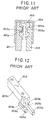
- Figure 10 shows a partial sectional view of a slider of a substantially conventional disk cartridge
- a slider 101 has an end portion provided with a spring insertion hole 101a for inserting a spring (not shown), the insertion hole 101a being formed so as to provide a tapered surface which is made narrow in its depth direction.
- a window portion 101b elongated in the bilateral direction thereof is formed to the bottom, i.e. upper end, as viewed, portion of the insertion hole 101a so that an engaging portion of the spring is engaged with the window.
- the slider 101 is provided with flat sliding surfaces 101c, 101c which slide along upper and lower shells, not shown, of a disk cartridge. Further, with reference to Figure 10C, the slider 101 is also provided with leg portions 101d, 101d, each of which is composed of a recessed portion 101e extending in a direction normal to the longitudinal direction of the body of the slider 101 and a projection 101f projecting outward from the end of the recessed portion 101e.
- FIG 11 shows a sectional view of an important portion of a substantially conventional disk cartridge, in which reference numeral 201 denotes an upper shell to which a lower shell 202 is bonded.
- a slider 203 is disposed between the upper shell 201 and the lower shell 202 to be slidable, and a shutter 204 is fixed to the slider 203.
- the slider 203 is formed with recessed portions 203a, 203a, each having substantially ⁇ -shape, which are engaged with protruded portions 201a, 202a, each having substantially ⁇ -shape, formed to the upper and lower shells 201 and 202, respectively. Through the engagement between these recessed and protruded portions, the slider 203 is prevented from coming off from the upper and lower shells 201 and 202.
- Figure 12 is a perspective view of an important portion of the slider 203 to be usable for a disk cartridge of conventional structure.
- the leg portion 203b is formed to the end portion of the slider 203 so as to project outward in a direction normal to the body portion 203c of the slider 203, and the leg portion 203b is provided at its end portion with a projection 203d extending outward in the longitudinal direction of the body portion 203c of the slider 203.
- the projections 203d formed to the end portions of both leg portions 203b are engaged with the upper and lower shells 201 and 202, respectively, to thereby prevent the slider 203 from coming off from the shells 201 and 202.
- the slider having the tapered insertion hole 101 it is easy to insert a spring at a time of manufacturing.
- the insertion hole has a wide opening area, the strength of the slider itself is made weak, providing a problem.
- an urging force of the spring varies, and in such case, there provides a problem that the shutter cannot be smoothly moved, thus also providing a problem.
- the slider has the flat sliding surfaces, the slider will be easily come off.
- the leg portion is composed of the recessed portion and the projection to provide an L-shape, the slider is likely come off.
- the recessed portion of the slider has a thin thickness, being weak in strength at this portion, and when the shells are likely bent, the slider will be easily come off, also providing a problem. Still furthermore, since the slider has a complicated structure, it is difficult to manufacture the slider, and particularly, it is further difficult to manufacture the same with high dimensional precision.
- a disk cartridge comprising upper and lower shells bonded to define an inner hollow portion in which a slider is movable, a shutter coupled to the slider, and a resilient member for urging the slider in one direction, wherein said slider has an insertion hole in which one end engaging portion of the resilient member is received, said insertion hole being defined by a substantially flat surface extending substantially parallel to a longitudinal direction of the slider and by a surface which is inclined with respect to the flat surface, and wherein the insertion hole has an end engaging hole portion shaped to limit the movement of the end engaging portion of the resilient member.
- the present invention further provides a disk cartridge which comprises an upper shell, a lower shell to be bonded to the upper shell with an inner hollow portion, a slider disposed to be movable in the hollow portion formed between the upper and lower shells, a shutter attached to the slider and an elastic member disposed between the slider and the upper or lower shell for urging the slider in one direction, wherein the slider is formed with an insertion hole into which one end engaging portion of the elastic member is inserted, the insertion hole being defined by a flat surface in substantially parallel to a longitudinal direction of the slider and an inclining surface having inclination with respect to the flat surface, and the insertion hole is formed with an end engaging hole portion at a deepest portion thereof, the end engaging hole portion having a shape or volume capable of limiting a movement of the end engaging portion of the elastic member.
- a disk cartridge comprising upper and lower shells bonded to define an inner hollow portion in which a slider is movable, a shutter coupled to the slider, and an elastic member for urging the slider in one direction, wherein said slider has sliding surfaces for sliding with respect to respective facing surfaces of the upper and lower shells, and wherein at least one of the sliding or facing surfaces has a recessed portion in which a protruding portion of the respective facing or sliding surface is engaged.
- a disk cartridge which comprises an upper shell, a lower shell to be bonded to the upper shell with an inner hollow portion, a slider disposed to be movable in the hollow portion formed between the upper and lower shells, a shutter attached to the slider and an elastic member disposed between the slider and the upper or lower shell for urging the slider in one direction, wherein the slider is formed with sliding surfaces with respect to the upper and lower shells, at least one of the sliding surfaces being formed with a recessed portion which is engaged with a protruded portion formed to a surface, facing the sliding surface of the slider, of at least one of the upper and lower shells.
- the invention also extends to a disk cartridge comprising upper and lower shells bonded to define an inner hollow portion in which a slider is movable, and a shutter coupled to the slider, and an elastic member for urging the slider in one direction, wherein said slider has longitudinal end portions to which leg portions are formed, one of said leg portions being formed with a first engaging portion and one of said upper and lower shells is formed with a second engaging portion which is engaged with the first engaging portion when the shutter is in a closed position.
- a disk cartridge which comprises an upper shell, a lower shell to be bonded to the upper shell with an inner hollow portion, a slider disposed to be movable in the hollow portion formed between the upper and lower shells, a shutter attached to the slider and an elastic member disposed between the slider and the upper or lower shell for urging the slider in one direction, wherein the slider has longitudinal end portions to which leg portions are formed, one of the leg portions being formed with a first engaging portion and one of the upper and lower shells is formed with a second engaging portion which is engaged with the first engaging portion when the shutter is in a closed position.
- a disk cartridge which comprises an upper shell, a lower shell to be bonded to the upper shell with an inner hollow portion, a slider disposed to be movable in the hollow portion formed between the upper and lower shells and a shutter attached to a mounting surface of the slider, wherein the upper and lower shells are provided with flanged portions extending inward toward the slider and the slider is formed with cutouts at the shutter mounting surface which are engaged with the flanged portions.
- the slider is composed of side leg portions extending along the longitudinal direction thereof and a connection portion connecting the side leg portions and the mounting surface is formed to the connection portion.
- a further cutout is formed to an end portion of at least one of the side leg portions, the further cutout being engaged with a staged portion formed to a surface, facing the side leg portion, of at least one of the upper and lower shells.
- Embodiments of the invention enable a disk cartridge to be provided which is capable of preventing a slider from coming off without changing an urging force of a spring member.
- Embodiments of the invention provide a disk cartridge whose slider is easy to manufacture and has improved strength.
- the spring insertion hole is defined by the flat surface and the inclining surface, the opening area of the insertion hole is reduced in comparison with the tapered hole of the conventional structure, thus improving the strength of the slider.
- the hole portion into which one end of the elastic member is fitted has a shape suitable for limiting the movement of the end portion of the elastic member, the movement of the slider is made stable.
- the movement of the slider can be further made stable through the engagement between the recessed portion formed to the sliding surface of the slider and the protruded portion formed to the upper or lower shell, thereby preventing the slider from coming off. Since the engaging portion formed to the leg portion of the slider and the engaging portion formed to the upper or lower shell are engaged together at the shutter closing time, the coming off of the slider can be effectively prevented even if any impact is applied to the disk cartridge.
- the disk cartridge comprises a lower shell 1 and an upper shell 2 which is bonded to the lower shell with an inner hollow portion therebetween in which a disk 11 is accommodated to be turnable.
- the lower shell 1 and the upper shell 2 are formed with openings, only the opening 2a of the upper shell 2 being shown, and a shutter 3 is provided to be reciprocal in a direction along an arrow in Figure 1 to open or shut the opening 2a.
- a slider 4 is further disposed in the inner hollow portion between the lower and upper shells 1 and 2 to be movable or slidable along the arrowed direction and the shutter 3 is secured to the slider 4 by means of, for example, a screw (not shown).
- a coil spring 5 is interposed between the slider 4 and a body of the cartridge so that the shutter 3 always covers the opening 2a of the upper shell 2.
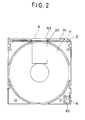
- Figure 2 shows an inner plan view of the upper shell 2 for a disk cartridge of the present invention.
- a light protector 6 is accommodated in the upper shell 2, which is formed with a guide 2b for guiding the movement of the light protector 6.
- Figures 3A to 3C represent the slider 4 for a disk cartridge of the present invention.
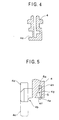
- the slider 4 is formed with a groove 4a as shown in Figure 4 at a proper portion of the slider 4, the groove 4a extending in the longitudinal direction of the slider 4.
- the upper shell 2 is formed with a protruded portion 2c having a shape capable of being engaged with the groove 4a of the slider 4, and the coming-off of the slider 4 at the slider moving time can be prevented through the engagement between the protruded portion 2c and the groove 4a.
- the slider 4 has both ends to which are formed leg portions 4b, 4b, one of which, the lower one as viewed in Figure 3A, is formed with an outward projection 4c and an inward projection 4d.
- the inward projection 4d is engaged with a recessed portion 2d formed to the upper shell 2 when the shutter 3 is closed, thereby preventing the slider 4 from coming off at the shutter closing time.
- the slider 4 is formed at its one end with an insertion hole 4g into which an end engaging portion 5a of a coil spring 5 is inserted.
- the insertion hole 4g is defined by a flat surface 4e in parallel to the longitudinal direction of the slider 4 and an inclining surface 4f having an inclination with respect to the flat surface 4e.
- the insertion hole 4g is provided with an engaging hole portion 4h at the deepest portion thereof with which the end engaging portion 5a of the coil spring 5 is engaged when the coil 5 is inserted into the insertion hole 4g. Since the engaging hole portion 4h has a volume suitable for the shape of the end engaging portion 5a of the coil spring 5, when the coil spring 5 is inserted into the insertion hole 4g, the coil spring 5 is not largely moved therein.
- the slider 4 when the slider 4 is moved and even if the urging force of the coil spring 5 changes, the change of the urging force of the coil spring 5 due to the positional change of the end engaging portion 5a of the coil spring 5 with respect to the engaging hole portion 4h is substantially not caused, thus the slider 4 being stably moved.
- the insertion hole 4g is defined by the flat surface 4e having no inclination or taper with respect to the longitudinal direction of the slider 4, the opening area of the insertion hole 4g can be made small, thus improving the strength of the slider 4.
- Figure 6 shows another embodiment of the disk cartridge of the present invention, in which the slider 4 is composed of side leg portions 4p and 4q extending in its longitudinal direction and a connection portion connecting the side leg portions 4p, 4q with space, and flanged portions la and 2e are formed to the upper, as viewed, ends of the lower and upper shells 1 and 2 so as to project inwardly of the disk cartridge.
- the slider 4 is provided at its width side ends with cutouts 4j, 4j to a mounting surface 4i of the slider 4 to which the shutter 3 is mounted, and the cutouts 4j, 4j have shapes corresponding to the shapes of the flanged portions la and 2e so that the flanged portions la and 2e can be firmly engaged with the cutouts 4j, 4j, respectively, to thereby firmly prevent the slider from coming off from the body of the disk cartridge.
- a cutout 4k is further formed to the slider 4 at a lower end portion of the side leg portion 4p, as viewed, thereof.
- the upper shell 2 is provided with a staged portion as an engaging portion 2f, which is engaged with the cutout 4k, and the lower shell 1 is also provided with a staged portion lc, which is engaged with a lower end portion of the other side leg portion 4q of the slider 4.
- the one side leg portion 4p of the slider 4 faces the upper shell 2 and the other side leg portion 4q thereof faces the lower shell 1.
- the movement of the slider 4 in the longitudinal direction thereof is limited by the engagement between the lower and upper shells 1 and 2 and the slider end portions.
- the slider 4 is composed of a slider body 4 and a leg portion 4m formed to one end portion of the slider body 4 so as to extend in a direction, arrowed direction in Figure 7, normal to the longitudinal direction of the slider body.
- the structure can be made simple, thus easily manufacturing the same with reduced cost.
- the slider leg portion 4m has no projecting portion even in the shutter opened portion. According to such structure, although the slider 4 does not engage with an edge portion 1b of the lower shell 1, the slider 4 is engaged with the flanged portions 1a and 2e of the lower and upper shells 1 and 2, so that the slider 4 is never come off.
- Figure 9 shows a further embodiment of the present invention, in which a further cutout 4n is formed to the other side leg portion 4q of the slider 4 in addition to the cutout 4k for the one side leg portion 4p of the slider shown in Figure 6, which is engaged with the staged portion lc of the lower shell 1 to surely prevent the slider 4 from moving in the longitudinal direction, i.e. lower direction as viewed in Figure 9, of the slider 4.
- the opening area of the insertion hole can be made small, thus improving the strength of the slider.
- the movement of the slider can be suitably limited through the engagement of the spring member with the engagement hole formed to the slider. The slider can be surely prevented from coming off.
Landscapes
- Feeding And Guiding Record Carriers (AREA)
Applications Claiming Priority (4)
| Application Number | Priority Date | Filing Date | Title |
|---|---|---|---|
| JP254089/95 | 1995-09-29 | ||
| JP25408995A JPH0997486A (ja) | 1995-09-29 | 1995-09-29 | ディスクカートリッジ |
| JP255413/95 | 1995-10-02 | ||
| JP25541395A JPH09102179A (ja) | 1995-10-02 | 1995-10-02 | ディスクカートリッジ |
Publications (2)
| Publication Number | Publication Date |
|---|---|
| EP0766249A2 true EP0766249A2 (fr) | 1997-04-02 |
| EP0766249A3 EP0766249A3 (fr) | 1997-09-24 |
Family
ID=26541530
Family Applications (1)
| Application Number | Title | Priority Date | Filing Date |
|---|---|---|---|
| EP96307124A Ceased EP0766249A3 (fr) | 1995-09-29 | 1996-09-27 | Cassette à disque |
Country Status (1)
| Country | Link |
|---|---|
| EP (1) | EP0766249A3 (fr) |
Family Cites Families (8)
| Publication number | Priority date | Publication date | Assignee | Title |
|---|---|---|---|---|
| JPS6282579A (ja) * | 1985-10-07 | 1987-04-16 | Hitachi Maxell Ltd | デイスクカ−トリツジ |
| DE68929036T2 (de) * | 1988-04-28 | 1999-11-11 | Dai Nippon Insatsu K.K., Tokio/Tokyo | Plattenkassette |
| JPH02110069U (fr) * | 1989-02-13 | 1990-09-03 | ||
| KR960013773B1 (ko) * | 1990-01-29 | 1996-10-10 | 다이닛뽕 인사쓰 가부시기가이샤 | 디스크카트리지 |
| KR100252370B1 (ko) * | 1990-02-14 | 2000-04-15 | 기타지마 요시토시 | 3.5인치용의디스크카트리지 |
| JPH06131841A (ja) * | 1992-07-15 | 1994-05-13 | Matsushita Electric Ind Co Ltd | ディスクカートリッジ |
| EP0667616B1 (fr) * | 1994-02-15 | 2006-07-19 | Mitsubishi Chemical Corporation | Cassette à disque |
| JPH08306152A (ja) * | 1995-04-28 | 1996-11-22 | Toshiba Corp | ディスクカ−トリッジ |
-
1996
- 1996-09-27 EP EP96307124A patent/EP0766249A3/fr not_active Ceased
Also Published As
| Publication number | Publication date |
|---|---|
| EP0766249A3 (fr) | 1997-09-24 |
Similar Documents
| Publication | Publication Date | Title |
|---|---|---|
| US4382167A (en) | Push-button switch | |
| US6027350A (en) | Ejecting mechanism for card cartridge connector | |
| US7210950B2 (en) | Connector for memory card | |
| US5848919A (en) | Connector | |
| CN100583567C (zh) | 弹出部件与凸轮从动件和锁定部件整体联接的卡连接器 | |
| KR860009414A (ko) | 디스크 카트리지 | |
| GB2302611A (en) | Lock structure for cover of electronic appliance | |
| GB2247989A (en) | Push button switch | |
| US20070004258A1 (en) | Card connector | |
| JP7643086B2 (ja) | コイル部品 | |
| CN102577658A (zh) | 保持器和噪音电流吸收器 | |
| EP1667287B1 (fr) | Connecteur électrique dans lequel la connexion du connecteur correspondant détermine le mouvement de la pièce de connexion flottante | |
| EP0766249A2 (fr) | Cassette à disque | |
| JP2825445B2 (ja) | コネクタ | |
| JPS6294279A (ja) | カセツト式ステ−プラ | |
| US6230978B1 (en) | Card ejection device of electronic card connector | |
| KR100975187B1 (ko) | 하우징 및 이를 구비한 커넥터 구조, 그리고 이 커넥터 구조를 구비하는 전기 기구 | |
| JP3274521B2 (ja) | ラッチ装置 | |
| JP3129138B2 (ja) | 板材保持構造 | |
| JP3098548B2 (ja) | ラッチ装置のトレース部材取付構造 | |
| JPH0541468Y2 (fr) | ||
| EP0901138B1 (fr) | Commutateur à curseur | |
| JP3341558B2 (ja) | 片口金蛍光灯ソケット | |
| JP2000133372A (ja) | プラグ挿入口の開閉構造 | |
| EP0713612B1 (fr) | Connecteur electrique |
Legal Events
| Date | Code | Title | Description |
|---|---|---|---|
| PUAI | Public reference made under article 153(3) epc to a published international application that has entered the european phase |
Free format text: ORIGINAL CODE: 0009012 |
|
| AK | Designated contracting states |
Kind code of ref document: A2 Designated state(s): DE FR GB NL |
|
| PUAL | Search report despatched |
Free format text: ORIGINAL CODE: 0009013 |
|
| AK | Designated contracting states |
Kind code of ref document: A3 Designated state(s): DE FR GB NL |
|
| 17P | Request for examination filed |
Effective date: 19971208 |
|
| 17Q | First examination report despatched |
Effective date: 19980618 |
|
| GRAG | Despatch of communication of intention to grant |
Free format text: ORIGINAL CODE: EPIDOS AGRA |
|
| STAA | Information on the status of an ep patent application or granted ep patent |
Free format text: STATUS: THE APPLICATION HAS BEEN REFUSED |
|
| 18R | Application refused |
Effective date: 20020817 |