EP0767036A1 - Drahtsäge mit einem Drahtmanagementsystem dass eine Verwendung von Drahtzylindern sehr grosser Länge erlaubt - Google Patents
Drahtsäge mit einem Drahtmanagementsystem dass eine Verwendung von Drahtzylindern sehr grosser Länge erlaubt Download PDFInfo
- Publication number
- EP0767036A1 EP0767036A1 EP96115198A EP96115198A EP0767036A1 EP 0767036 A1 EP0767036 A1 EP 0767036A1 EP 96115198 A EP96115198 A EP 96115198A EP 96115198 A EP96115198 A EP 96115198A EP 0767036 A1 EP0767036 A1 EP 0767036A1
- Authority
- EP
- European Patent Office
- Prior art keywords
- wire
- sawing
- spool
- axis
- rotation
- Prior art date
- Legal status (The legal status is an assumption and is not a legal conclusion. Google has not performed a legal analysis and makes no representation as to the accuracy of the status listed.)
- Granted
Links
- 238000004804 winding Methods 0.000 claims abstract description 22
- 238000005520 cutting process Methods 0.000 claims description 6
- 238000007726 management method Methods 0.000 description 11
- 239000000463 material Substances 0.000 description 4
- VYPSYNLAJGMNEJ-UHFFFAOYSA-N silicon dioxide Inorganic materials O=[Si]=O VYPSYNLAJGMNEJ-UHFFFAOYSA-N 0.000 description 4
- 238000010276 construction Methods 0.000 description 3
- 230000001133 acceleration Effects 0.000 description 2
- 230000005587 bubbling Effects 0.000 description 2
- 230000001419 dependent effect Effects 0.000 description 2
- 239000010432 diamond Substances 0.000 description 2
- 229910003460 diamond Inorganic materials 0.000 description 2
- 238000004519 manufacturing process Methods 0.000 description 2
- 238000005259 measurement Methods 0.000 description 2
- 238000000034 method Methods 0.000 description 2
- 239000010453 quartz Substances 0.000 description 2
- 229910052594 sapphire Inorganic materials 0.000 description 2
- 239000010980 sapphire Substances 0.000 description 2
- 229910001218 Gallium arsenide Inorganic materials 0.000 description 1
- 229910000639 Spring steel Inorganic materials 0.000 description 1
- 229910000831 Steel Inorganic materials 0.000 description 1
- 239000003082 abrasive agent Substances 0.000 description 1
- PNEYBMLMFCGWSK-UHFFFAOYSA-N aluminium oxide Inorganic materials [O-2].[O-2].[O-2].[Al+3].[Al+3] PNEYBMLMFCGWSK-UHFFFAOYSA-N 0.000 description 1
- 239000000919 ceramic Substances 0.000 description 1
- 229910010293 ceramic material Inorganic materials 0.000 description 1
- 239000003795 chemical substances by application Substances 0.000 description 1
- 239000013065 commercial product Substances 0.000 description 1
- 238000011161 development Methods 0.000 description 1
- 238000005516 engineering process Methods 0.000 description 1
- 230000002349 favourable effect Effects 0.000 description 1
- 229910052733 gallium Inorganic materials 0.000 description 1
- 239000000203 mixture Substances 0.000 description 1
- 238000012986 modification Methods 0.000 description 1
- 230000004048 modification Effects 0.000 description 1
- 229910021421 monocrystalline silicon Inorganic materials 0.000 description 1
- 229910021420 polycrystalline silicon Inorganic materials 0.000 description 1
- 238000003825 pressing Methods 0.000 description 1
- 230000001105 regulatory effect Effects 0.000 description 1
- 230000002441 reversible effect Effects 0.000 description 1
- 229910052710 silicon Inorganic materials 0.000 description 1
- 239000010703 silicon Substances 0.000 description 1
- HBMJWWWQQXIZIP-UHFFFAOYSA-N silicon carbide Chemical compound [Si+]#[C-] HBMJWWWQQXIZIP-UHFFFAOYSA-N 0.000 description 1
- 229910010271 silicon carbide Inorganic materials 0.000 description 1
- 239000000377 silicon dioxide Substances 0.000 description 1
- 230000003068 static effect Effects 0.000 description 1
- 239000010959 steel Substances 0.000 description 1
- 238000012546 transfer Methods 0.000 description 1
- 229910000859 α-Fe Inorganic materials 0.000 description 1
Images



Classifications
-
- B—PERFORMING OPERATIONS; TRANSPORTING
- B65—CONVEYING; PACKING; STORING; HANDLING THIN OR FILAMENTARY MATERIAL
- B65H—HANDLING THIN OR FILAMENTARY MATERIAL, e.g. SHEETS, WEBS, CABLES
- B65H57/00—Guides for filamentary materials; Supports therefor
- B65H57/18—Guides for filamentary materials; Supports therefor mounted to facilitate unwinding of material from packages
- B65H57/20—Flyers
-
- B—PERFORMING OPERATIONS; TRANSPORTING
- B28—WORKING CEMENT, CLAY, OR STONE
- B28D—WORKING STONE OR STONE-LIKE MATERIALS
- B28D5/00—Fine working of gems, jewels, crystals, e.g. of semiconductor material; apparatus or devices therefor
- B28D5/04—Fine working of gems, jewels, crystals, e.g. of semiconductor material; apparatus or devices therefor by tools other than rotary type, e.g. reciprocating tools
- B28D5/045—Fine working of gems, jewels, crystals, e.g. of semiconductor material; apparatus or devices therefor by tools other than rotary type, e.g. reciprocating tools by cutting with wires or closed-loop blades
-
- B—PERFORMING OPERATIONS; TRANSPORTING
- B65—CONVEYING; PACKING; STORING; HANDLING THIN OR FILAMENTARY MATERIAL
- B65H—HANDLING THIN OR FILAMENTARY MATERIAL, e.g. SHEETS, WEBS, CABLES
- B65H54/00—Winding, coiling, or depositing filamentary material
- B65H54/02—Winding and traversing material on to reels, bobbins, tubes, or like package cores or formers
- B65H54/28—Traversing devices; Package-shaping arrangements
- B65H54/2803—Traversing devices; Package-shaping arrangements with a traversely moving package
-
- B—PERFORMING OPERATIONS; TRANSPORTING
- B65—CONVEYING; PACKING; STORING; HANDLING THIN OR FILAMENTARY MATERIAL
- B65H—HANDLING THIN OR FILAMENTARY MATERIAL, e.g. SHEETS, WEBS, CABLES
- B65H54/00—Winding, coiling, or depositing filamentary material
- B65H54/02—Winding and traversing material on to reels, bobbins, tubes, or like package cores or formers
- B65H54/28—Traversing devices; Package-shaping arrangements
- B65H54/2896—Flyers
Definitions
- the present invention relates to a wire sawing device comprising a sawing zone in which a workpiece to be sawn is in abutment against the wire capable of being moved in an alternating or continuous movement to saw the workpiece and a wire management device comprising a supply reel supplying new wire to the sawing area and a take-up reel taking up the used wire coming from the sawing area.
- Known sawing devices most often comprise a sheet of wires capable of moving in a continuous or reciprocating movement pressing against a piece to be sawed in slices, thus defining a sawing zone.
- the sawing area consists of a set of cylinders placed in parallel. These cylinders, called wire guides, are engraved with grooves defining the interval between the wires of the sheet, that is to say the thickness of the slices to be sawed.
- the piece to be sawn is fixed on a support table which moves perpendicular to the wire table.
- the traveling speed defines the cutting speed.
- the wire renewal as well as the tension control is done in a part called "wire management area" and located outside the sawing area proper.
- the agent which will govern the cutting is either an abrasive fixed on the wire, or a free abrasive brought by bubbling.
- the wire acts only as a conveyor.
- the wire used even if it acts only as a conveyor, undergoes a certain wear which will have to be compensated by a rate of renewal which will be defined by the sawn surface per unit of time.
- the current development of wire sawing is driven by the tendency of users to move towards sawing large pieces, therefore large areas and therefore a large consumption of wire.
- the use of long wires becomes imperative.
- the wire management systems commonly used in sawing devices are produced by the use of coils mounted horizontally or vertically on a motorized axis whose speed is managed by a device regulating the flow rate and the wire tension via an electronic control.
- the wire will therefore pass from a reel of new wire to the sawing area to return after use to a reel of used wire.
- an asymmetrical longitudinal back-and-forth movement is applied, asymmetry being used to adjust the renewal rate.
- the longitudinal back and forth movement will impose on the reels of new and used wire frequent changes of direction with strong accelerations.
- Wire sawing devices of the aforementioned type are already known especially in the electronic components, ferrites, quartz and silica industry, for obtaining thin slices of materials such as poly or monocrystalline silicon or new materials.
- materials such as poly or monocrystalline silicon or new materials.
- materials such as GaAs, InP, GGG (gadolinium-gallium garnets) or also quartz, synthetic sapphire, and ceramic materials.
- the high price of these materials makes wire sawing more attractive compared to other techniques such as diamond disc sawing.
- These wire sawing devices use a steel wire with a diameter generally between 0.1 and 0.2 mm, typically 0.18 mm.
- the running length is between 100 and 300 km, therefore with a maximum weight of 60 kg, not including the support coil.
- the precision of the pieces to be sawed which is very important for electronic applications, depends on the management of the wire and its consumption.
- the control of consumption will allow the control of the wear of the wire adapted to the increasing requirements of the technology which authorizes the manufacture of sawn pieces of larger diameter and greater length. This trend requires consumption control adapted to these new possibilities and this fact necessitates the use of very long wires which are not conducive to current systems.
- the aims of the present invention therefore consist in overcoming the limitations of known sawing devices, which can only manage limited lengths of wire, in eliminating the inertia factor of the coils in rotation during large accelerations and decelerations, to make it possible very long wire lengths and to obtain high sawing precision.
- the device according to the present invention is characterized in that the thread management device comprises at least one rotary unwinding and / or rewinding member mounted in a rotatable manner around the periphery of this reel and arranged so as to unwind and / or rewind the wire with an adjustable rate.
- the invention allows the use of coils of heavy wire having a large diameter without the use of high power motors being necessary. It will also allow you to work for long periods without human intervention, thereby improving productivity and quality.
- static coils or in any case without rapid rotation, and by winding or unwinding the wire by a device rotating around them, the inertia is no longer dependent on the weight of the wire or that of the coil, but only that of the winding or unwinding device which can be made as light as possible.
- Wire lengths only become limited by market availability, and thus 400 kg spools containing up to 2000 km of 0.18 diameter wire are made possible.
- non-rotating wire spools therefore makes it possible to produce a wire sawing device having an extended operating autonomy with very long lengths of wire, without the wire control system being affected by the mass thereof. This. This will make it possible to have a more regular flow, to obtain higher speeds while keeping the operational advantages and a high cutting precision.
- An advantageous embodiment is characterized in that the wire is arranged in the sawing zone in the form of a sheet of parallel wires, in that the two supply and take-up coils are mounted in a non-rotatable manner on a support and that the wire management device comprises two rotary members rotatably mounted around the two coils and arranged so as to act as flow rate and wire tension regulators.
- a sawing device of a simple construction is thus obtained, of a reliable, fast, precise and entirely independent operation of the weight of the two spools of threads and comprising an efficient, uncomplicated regulation of the flow rate and of the tension of the thread, and of a low cost price.
- said rotary member comprises a winding head rotatably mounted around the periphery of the spool and comprising at least a first return element arranged to guide the wire coming from or ending at the spool in the direction of a second element of dismissal.
- the second deflection element can favorably be arranged so that the wire is disposed substantially on the axis of rotation of said rotary member coincides with the axis of the spool and arranged so as to guide the wire towards the sawing zone.
- the first deflection element comprises a first pulley of which a normal to the axis of rotation is substantially perpendicular to the axis of the coil around which it rotates and a second pulley whose axis of rotation is mounted rotating around a shaft arranged so that the wire terminates substantially tangentially to the coil regardless of the degree of filling of the latter.
- the wire can thus be wound and unwound from the beginning to the end of the spool, very regularly and with a precise orientation.
- the rotary member comprises an arm equipped with said winding head and having the axis of rotation as the axis of rotation.
- the rotary member may comprise a ring concentric with the coil and carrying said winding head driven by a motor rotating on the ring.
- the rotary member may comprise a ring concentric with the coil formed by a bearing with two rings, the winding head being fixed on one of the rings driven in rotation by a motor.
- the function of slitting the coils is achieved by an axial reciprocating movement thereof by means of a mechanical, electrical, hydraulic or pneumatic drive member.
- the wire can thus be wound very evenly on the spools.
- the back-and-forth movement along the axis of the coil is applied, with an amplitude which is equal to the filling length defined by the distance between the flanges of the coil.
- the sawing device will therefore be in the form of two modules, one containing the sawing zone composed of the wire guide cylinders supporting the wire ply and the support table which moves perpendicular to the wire ply , the other containing the wire management, will be made up of support of reels on which the delivery and reception coils will be posed. These may be driven back and forth to carry out the slicing operation, namely the successive winding wire against wire.
- Each of the spools of thread is assigned a winding or unwinding system rotating around it. This function can be achieved for example by a rotating arm centered on the axis of the coil having at its ends a pulley device with various references or by an external rail supporting a carriage with the pulleys.
- FIG. 1 schematically represents a conventional sawing device, used before the present invention.
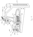
- Figure 2 is a schematic view of an embodiment of the sawing device according to the present invention.
- FIG. 3 is a schematic view of a detail of FIG. 2.
- Figures 4 and 5 are schematic views of two variants.
- the new wire 1 comes out of the supply reel 2 which is driven by a motor 3.
- a tension measurement 4 corrects a tension arm 5 coupled to a motor 6.
- the wire then passes into the sawing zone 40, around the wire guides 7 to form the sheet of wires 8.
- the workpiece 9 fixed on a support table 10 comes to bear against it to be sawn by the abrasive 11 coming from a distributor 12 and driven by the wires of the ply 8.
- the used wire 13 leaves the ply and returns to the take-up reel 14 via the tension arm 5, the tension measurement 4 and the transfer pulley 15 actuated back and forth sideways by the motor 16.
- the wire management device 41 therefore comprises coils 2 and 14 mounted to rotate about their axis.
- FIG. 2 schematically illustrates an embodiment of the present invention.
- the new wire 1 comes out of the supply reel 2a around which an arm 17 supporting pulleys 18,19,20,21 rotates.
- the motor of the arm 22 gives the tension to be applied to the wire 1, this tension being given by a measuring gauge 4.
- the wire 1 goes towards the sawing zone 40 composed of the same elements as in FIG. 1.
- the used wire 13 returns to the take-up reel 14a via the measuring gauge 4 and the rotary arm 17.
- the feed-back coils 2a and take-up 14a can be driven back and forth generated by a driving device 23 for cross-checking purposes.
- the wire management device 41a can be perfectly reversible.
- the coils 2a and 14a are fixedly mounted, not rotatable on any support.
- the arms 17 with their pulleys 18 to 21 each form a rotary member 42 for unwinding and / or rewinding rotatably mounted around the periphery of the reels and arranged so as to unwind and / or rewind the wire with a flow rate adjustable by the speed of the motors 22.
- the measuring gauges 4 are connected to the control of the motors 22, so that the rotary members 42 act as flow rate and thread tension regulators.
- FIG. 3 represents a possibility of producing the wire management device 41a according to the invention.
- the wire enters via a pulley 18, fixedly oriented and coupled to the tension gauge 4, coming from the sawing zone 40.
- the latter passes through a bearing 24 to which is fixed the tension arm 17 driven by the tension and rotation motor 22 fixed on a support 26. It passes around the pulleys 19 and 20 fixed relative to the arm and having parallel axes of rotation.
- the output pulley 21 can be rotatable relative to the shaft 25 to maintain a fixed orientation relative to the wire following the filling of the take-up reel 14.
- the bearing 24 supports the rotary arm 17 with its pulley system.
- the coil is driven back and forth generated by a mechanism 23 which can be electric, hydraulic, pneumatic or other.
- the pulleys 20, 21 therefore form a winding head 29 rotatably mounted around the periphery of one of the coils 2a, 14a.
- the pulley 21 constitutes a deflection member arranged to guide the wire coming from or ending at the spool in the direction of the pulley 20.
- the latter guides the wire towards the pulleys 19 and 18 which are arranged so that the wire is disposed substantially on the axis of rotation of the bearing 24, coincident with the axis of the coil. From the pulley 18, the wire then passes to the sawing zone 40.
- the pulley 20 has an axis of rotation such that a normal to this axis is substantially perpendicular to the axis of the coil. As the pulley 21 rotates around the shaft 25 the wire terminates substantially tangentially to the spool regardless of the degree of filling of the latter.
- FIG. 4 represents a variant making it possible to perform the function using a linear motor 27 rotating on a ring or a concentric circular rail 28 to coil 2a.
- the carriage 29b of the linear motor 27 forming the winding head supports the necessary pulleys 20b and 21b.
- the pulley 18b coupled to the tension gauge 4b, as well as the bearing 24b are fixedly mounted on the support 26b and the pulley 19b rotatable relative to the pulley 18b is fixed on the bearing 24b.
- the pulley 21b is rotatably mounted on the shaft 25b, while the pulley 20b has an axis of rotation fixed relative to the carriage 29b.
- the second variant shown in FIG. 5 comprises a support 26c and mobile support arm 26d carrying the fixed, non-rotating coil 2a.
- the motor 23d which can be of the mechanical, electrical, hydraulic, pneumatic or other type
- the support arm 26d can be moved vertically to perform the slicing function, corresponding to a transverse, axial reciprocating movement of the spool so as to wind the wire gradually.
- a ring concentric with the coil is formed by a ball bearing 30 comprising two rings.
- the winding head 29c is mounted on the inner ring 32 driven in rotation by the motor 31, for example as a function of the signals received from the tension gauge or from another control element.
- the pulleys 18c and 20c have axes of rotation with a fixed orientation relative to the support 26c, respectively to the winding head 29c, while the pulleys 19c and 21c are rotatably mounted relative to the support 26c thanks to the bearing 24c, respectively relative to the winding head 29c thanks at tree 25c.
- the coils 2a, 14a could be rotatably mounted on their support arm 26d (fig. 5) and driven in rotation to pass the wire at a continuous rate from the supply reel to the take-up reel. There would then be a first reciprocating movement of sawing the wire obtained thanks to the rotary members 42 with their winding head 29 and a second continuous movement of rewinding the wire on the take-up reel to compensate for the wear of the latter.
- the reciprocating sawing movement may then have a higher speed, for example 20 m / sec, than that of the continuous movement, for example 1 to 2 m / sec.
- the saw wire forming the sheet of wires 8 is made of spring steel with a diameter of between 0.1 and 0.2 mm in order to saw blocks of hard materials or more specific compositions, such as silicon, ceramic , composed of elements from groups III-V, GGG, sapphire, etc., in slices of 0.1 to 5mm thick approximately.
- the abrasive agent is a commercial product and can be diamond, silicon carbide, alumina, etc., in a form fixed to the wire or in free form in bubbling.
- the sawing device makes it possible, by the use of heavy coils 2a, 14a, containing long lengths of wire, to rationalize the sawing operation and to cut large-sized sawn pieces 9 while obtaining the necessary precision.
- the general concept of the machine is simplified, making it possible to obtain for the user, lower investment and more economical operation.
- the device for sawing may present in the sawing area only a single wire, instead of a sheet of son. It could also include a single non-rotating coil, either debtor or receiver, and another wire management device at the other end, for example a conical monoflasque coil.
- the bobbin cutting function could also be achieved by a transverse reciprocating movement of the winding head parallel to the axis of the coils.
- the pulleys 18 to 21 could be replaced by any other suitable return and guide member.
- the orientation of the axis of the coils 2a, 14a could be different, vertical or oblique.
Landscapes
- Engineering & Computer Science (AREA)
- Mechanical Engineering (AREA)
- Finish Polishing, Edge Sharpening, And Grinding By Specific Grinding Devices (AREA)
- Processing Of Stones Or Stones Resemblance Materials (AREA)
Applications Claiming Priority (3)
| Application Number | Priority Date | Filing Date | Title |
|---|---|---|---|
| CH277795 | 1995-10-03 | ||
| CH2777/95 | 1995-10-03 | ||
| CH02777/95A CH691292A5 (fr) | 1995-10-03 | 1995-10-03 | Dispositif de sciage par fil équipé d'un système de gestion de fil permettant l'utilisation de bobines de fil de très grande longueur. |
Publications (2)
| Publication Number | Publication Date |
|---|---|
| EP0767036A1 true EP0767036A1 (de) | 1997-04-09 |
| EP0767036B1 EP0767036B1 (de) | 2002-11-13 |
Family
ID=4241372
Family Applications (1)
| Application Number | Title | Priority Date | Filing Date |
|---|---|---|---|
| EP96115198A Expired - Lifetime EP0767036B1 (de) | 1995-10-03 | 1996-09-21 | Drahtsäge mit einem Drahtmanagementsystem dass eine Verwendung von Drahtzylindern sehr grosser Länge erlaubt |
Country Status (5)
| Country | Link |
|---|---|
| US (1) | US5829424A (de) |
| EP (1) | EP0767036B1 (de) |
| JP (1) | JPH09109013A (de) |
| CH (1) | CH691292A5 (de) |
| DE (1) | DE69624769T2 (de) |
Cited By (8)
| Publication number | Priority date | Publication date | Assignee | Title |
|---|---|---|---|---|
| EP0990498A1 (de) * | 1998-09-10 | 2000-04-05 | Wacker Siltronic Gesellschaft für Halbleitermaterialien Aktiengesellschaft | Verfahren und Vorrichtung zum Abtrennen einer Vielzahl von Scheiben von einem sprödharten Werkstück |
| CN102101325A (zh) * | 2010-12-15 | 2011-06-22 | 湖南宇晶机器实业有限公司 | 多线切割机自动排线装置的径向平衡机构 |
| EP2586554A1 (de) * | 2011-10-27 | 2013-05-01 | Applied Materials Switzerland Sàrl | Drahtsägenvorrichtung mit zwei unabhängigen Drahtnetze und Betriebsverfahren dafür |
| US8490658B2 (en) | 2009-02-26 | 2013-07-23 | Saint-Gobain Abrasives, Inc. | Automatic winding of wire field in wire slicing machine |
| CN104647622A (zh) * | 2015-02-11 | 2015-05-27 | 苏州硅峰太阳能科技有限公司 | 一种摇摆式硅锭的高效多线开方机 |
| CN106239747A (zh) * | 2016-08-26 | 2016-12-21 | 浙江顺联智能设备有限公司 | 金刚线截断机 |
| CN108972924A (zh) * | 2018-07-18 | 2018-12-11 | 阜宁协鑫光伏科技有限公司 | 硅片切割系统 |
| WO2023202218A1 (zh) | 2022-04-18 | 2023-10-26 | 厦门品河精密科技有限公司 | 一种石材大板多线切割机的切割装置及多线切割机 |
Families Citing this family (30)
| Publication number | Priority date | Publication date | Assignee | Title |
|---|---|---|---|---|
| CZ283541B6 (cs) * | 1996-03-06 | 1998-04-15 | Trimex Tesla, S.R.O. | Způsob řezání ingotů z tvrdých materiálů na desky a pila k provádění tohoto způsobu |
| JPH1110509A (ja) * | 1997-06-24 | 1999-01-19 | Nippei Toyama Corp | ワイヤソーの張力付与機構 |
| JPH11165250A (ja) * | 1997-12-08 | 1999-06-22 | Tokyo Seimitsu Co Ltd | ワイヤソー |
| JP4049900B2 (ja) * | 1998-08-20 | 2008-02-20 | 株式会社スーパーシリコン研究所 | ワイヤソー切断装置 |
| DE60033574T2 (de) | 2000-05-31 | 2007-11-15 | Memc Electronic Materials S.P.A. | Drahtsäge und verfahren zum gleichzeitigen schneiden von halbleiterbarren |
| US6889684B2 (en) | 2002-11-06 | 2005-05-10 | Seh America, Inc. | Apparatus, system and method for cutting a crystal ingot |
| CH696806A5 (fr) * | 2003-11-18 | 2007-12-14 | Walter Ebner | Scie à fil à mouvement alternatif. |
| DE102007016316A1 (de) * | 2007-04-04 | 2008-10-09 | Siemens Ag | Verfahren und System zum Trennen einer Vielzahl von keramischen Bauelementen aus einem Bauelementeblock |
| EP2110216B1 (de) * | 2008-04-14 | 2013-06-05 | Applied Materials, Inc. | Drahtsägevorrichtung und Betriebsverfahren dafür |
| US8881716B2 (en) * | 2010-02-08 | 2014-11-11 | Toyo Advanced Technologies Co., Ltd. | Wire saw with tension detecting means and guide roller speed control |
| SG183130A1 (en) * | 2010-02-08 | 2012-09-27 | Toyo Advanced Tech Co | Method of cutting workpiece with wire saw, and wire saw |
| DE102011082366B3 (de) * | 2011-09-08 | 2013-02-28 | Siltronic Ag | Einlagiges Wickeln von Sägedraht mit fest gebundenem Schneidkorn für Drahtsägen zum Abtrennen von Scheiben von einem Werkstück |
| EP2583777A1 (de) * | 2011-10-22 | 2013-04-24 | Applied Materials Switzerland Sàrl | Klemmanordnung für eine Drahtführung einer Drahtsäge |
| FR2988023A1 (fr) * | 2012-03-16 | 2013-09-20 | Sodetal Sas | Fil a scier, methode de fabrication d'un tel fil et utilisation |
| JP2013220482A (ja) * | 2012-04-13 | 2013-10-28 | Tokyo Seiko Co Ltd | ワイヤ式切断装置 |
| US20150114189A1 (en) * | 2012-09-17 | 2015-04-30 | Jon Khachaturian | Method and apparatus for removing underwater platforms |
| CN106862663B (zh) * | 2012-12-04 | 2019-01-04 | 梅耶博格(瑞士)公司 | 线材管理系统 |
| CN103224166B (zh) * | 2013-05-15 | 2017-02-08 | 长沙岱勒新材料科技股份有限公司 | 一种高速绕线机 |
| CN103448153B (zh) * | 2013-08-23 | 2016-02-03 | 蓝思科技股份有限公司 | 一种蓝宝石晶棒的切割工艺及其加工治具 |
| JP5994766B2 (ja) * | 2013-11-21 | 2016-09-21 | 信越半導体株式会社 | ワークの切断方法 |
| DE102015200198B4 (de) * | 2014-04-04 | 2020-01-16 | Siltronic Ag | Verfahren zum Abtrennen von Halbleiterscheiben von einem Werkstück mit einem Sägedraht |
| EP3023184A1 (de) | 2014-11-20 | 2016-05-25 | Meyer Burger AG | Verfahren und Vorrichtung zum Schneiden eines Werkstücks |
| CN104608264B (zh) * | 2015-02-11 | 2016-08-24 | 苏州硅峰太阳能科技有限公司 | 摇摆式大理石多线切割机 |
| CN105057823A (zh) * | 2015-08-01 | 2015-11-18 | 烟台力凯电子科技有限公司 | 一种多线切割机的张力摆臂限位柱装置 |
| JP6923828B2 (ja) * | 2015-09-15 | 2021-08-25 | キヤノンマーケティングジャパン株式会社 | ワイヤ放電加工装置 |
| TWI713832B (zh) * | 2017-04-28 | 2020-12-21 | 友達晶材股份有限公司 | 晶圓切片機及其收放線裝置與晶圓切片的方法 |
| WO2019008530A1 (en) | 2017-07-07 | 2019-01-10 | Meyer Burger (Switzerland) Ag | METHOD FOR WINDING A CUTTING WIRE |
| US10593537B1 (en) | 2019-03-21 | 2020-03-17 | Samuel Messinger | Longitudinal silicon ingot slicing machine and jig fixture |
| US11276577B2 (en) | 2019-03-21 | 2022-03-15 | Samuel Messinger | Longitudinal silicon ingot slicing apparatus |
| US12415296B2 (en) * | 2020-08-16 | 2025-09-16 | Viswesh Srinivasan | CNC wire cutting machine |
Citations (4)
| Publication number | Priority date | Publication date | Assignee | Title |
|---|---|---|---|---|
| US778059A (en) * | 1903-03-05 | 1904-12-20 | Inocencio Fernandez | Machine for cutting diamonds. |
| FR1591125A (de) * | 1968-10-17 | 1970-04-27 | ||
| US3841297A (en) * | 1971-12-01 | 1974-10-15 | Motorola Inc | Machine for cutting brittle materials |
| JPH07195263A (ja) * | 1993-12-29 | 1995-08-01 | Nippei Toyama Corp | ワイヤガイド装置 |
Family Cites Families (3)
| Publication number | Priority date | Publication date | Assignee | Title |
|---|---|---|---|---|
| US3843072A (en) * | 1973-02-12 | 1974-10-22 | Western Electric Co | Method of and apparatus for coiling wire |
| US5465917A (en) * | 1994-05-23 | 1995-11-14 | Kosch; Delmar D. | Welding wire dispenser with adjustable brake |
| JP3107143B2 (ja) * | 1995-07-14 | 2000-11-06 | 株式会社東京精密 | ワイヤソーのワイヤトラバース装置 |
-
1995
- 1995-10-03 CH CH02777/95A patent/CH691292A5/fr not_active IP Right Cessation
-
1996
- 1996-09-21 DE DE69624769T patent/DE69624769T2/de not_active Expired - Lifetime
- 1996-09-21 EP EP96115198A patent/EP0767036B1/de not_active Expired - Lifetime
- 1996-10-02 US US08/724,927 patent/US5829424A/en not_active Expired - Lifetime
- 1996-10-03 JP JP8281296A patent/JPH09109013A/ja active Pending
Patent Citations (4)
| Publication number | Priority date | Publication date | Assignee | Title |
|---|---|---|---|---|
| US778059A (en) * | 1903-03-05 | 1904-12-20 | Inocencio Fernandez | Machine for cutting diamonds. |
| FR1591125A (de) * | 1968-10-17 | 1970-04-27 | ||
| US3841297A (en) * | 1971-12-01 | 1974-10-15 | Motorola Inc | Machine for cutting brittle materials |
| JPH07195263A (ja) * | 1993-12-29 | 1995-08-01 | Nippei Toyama Corp | ワイヤガイド装置 |
Non-Patent Citations (1)
| Title |
|---|
| PATENT ABSTRACTS OF JAPAN vol. 95, no. 008 * |
Cited By (13)
| Publication number | Priority date | Publication date | Assignee | Title |
|---|---|---|---|---|
| US6390896B1 (en) | 1998-09-10 | 2002-05-21 | WACKER SILTRONIC GESELLSCHAFT FüR HALBLEITERMATERIALIEN AG | Method and device for cutting a multiplicity of disks from a hard brittle workpiece |
| EP0990498A1 (de) * | 1998-09-10 | 2000-04-05 | Wacker Siltronic Gesellschaft für Halbleitermaterialien Aktiengesellschaft | Verfahren und Vorrichtung zum Abtrennen einer Vielzahl von Scheiben von einem sprödharten Werkstück |
| US8490658B2 (en) | 2009-02-26 | 2013-07-23 | Saint-Gobain Abrasives, Inc. | Automatic winding of wire field in wire slicing machine |
| CN102101325A (zh) * | 2010-12-15 | 2011-06-22 | 湖南宇晶机器实业有限公司 | 多线切割机自动排线装置的径向平衡机构 |
| CN102101325B (zh) * | 2010-12-15 | 2014-05-21 | 湖南宇晶机器实业有限公司 | 多线切割机自动排线装置的径向平衡机构 |
| EP2586554A1 (de) * | 2011-10-27 | 2013-05-01 | Applied Materials Switzerland Sàrl | Drahtsägenvorrichtung mit zwei unabhängigen Drahtnetze und Betriebsverfahren dafür |
| CN103085182A (zh) * | 2011-10-27 | 2013-05-08 | 应用材料瑞士有限责任公司 | 使用两个独立线网的切片线锯、线锯装置及其工作方法的新概念 |
| CN104647622A (zh) * | 2015-02-11 | 2015-05-27 | 苏州硅峰太阳能科技有限公司 | 一种摇摆式硅锭的高效多线开方机 |
| CN106239747A (zh) * | 2016-08-26 | 2016-12-21 | 浙江顺联智能设备有限公司 | 金刚线截断机 |
| CN108972924A (zh) * | 2018-07-18 | 2018-12-11 | 阜宁协鑫光伏科技有限公司 | 硅片切割系统 |
| CN108972924B (zh) * | 2018-07-18 | 2020-07-17 | 阜宁协鑫光伏科技有限公司 | 硅片切割系统 |
| WO2023202218A1 (zh) | 2022-04-18 | 2023-10-26 | 厦门品河精密科技有限公司 | 一种石材大板多线切割机的切割装置及多线切割机 |
| EP4494829B1 (de) * | 2022-04-18 | 2026-04-15 | Xiamen Pinhe Precision Technology Co., Ltd. | Mehrdraht-schneidemaschine vom hubtyp mit vier säulen und vier führungsrädern für eine grosse steinplatte |
Also Published As
| Publication number | Publication date |
|---|---|
| DE69624769D1 (de) | 2002-12-19 |
| DE69624769T2 (de) | 2003-07-17 |
| EP0767036B1 (de) | 2002-11-13 |
| JPH09109013A (ja) | 1997-04-28 |
| CH691292A5 (fr) | 2001-06-29 |
| US5829424A (en) | 1998-11-03 |
Similar Documents
| Publication | Publication Date | Title |
|---|---|---|
| EP0767036B1 (de) | Drahtsäge mit einem Drahtmanagementsystem dass eine Verwendung von Drahtzylindern sehr grosser Länge erlaubt | |
| EP0281511B1 (de) | Drahtschneidevorrichtung | |
| BE1001272A3 (fr) | Machines a diviser et a rebobiner des bandes. | |
| EP0788857B1 (de) | Drahtsägevorrichtung | |
| EP0808701A2 (de) | Drahtsäge | |
| EP0040145A1 (de) | Vorrichtung zum Schneiden langer Fasern, insbesondere von Glasfasern | |
| EP1054748B1 (de) | Drahtsäge zum schneiden von dünnen scheiben mittels wenigstens zwei einander schneidenden sägedrahtgeweben | |
| EP1464461B1 (de) | Verfahren und Vorrichtung zum Drahtsägen | |
| EP1437209B1 (de) | Drahtsägevorrichtung | |
| EP0788858B1 (de) | Drahtsägevorrichtung | |
| EP0788859B1 (de) | Drahtsägevorrichtung | |
| EP0328610B1 (de) | Verfahren und vorrichtung zum schneiden von stäben aus harten materialien | |
| CH694182A5 (fr) | Dispositif de sciage par fil. | |
| EP0000853B1 (de) | Spulmaschine, insbesondere für thermoplastische Garne | |
| FR2529871A1 (fr) | Machine pour revetir une surface quelconque avec un materiau composite de fibres et de resine | |
| EP1711423B1 (de) | Aufwickelvorrichtung mit zwei antriebsrollen für durchlaufaufwickelmaschine mit gesteuerter anlegelast der antriebsrollen | |
| WO1991004839A1 (fr) | Procede et dispositif de mise sous tension de fil coupant dans une machine-outil de decoupe | |
| EP0002976B1 (de) | Vorrichtung zur kontinuierlichen Erzeugung von schraubenförmigen Nuten in einem zylindrischen Körper | |
| FR2757793A1 (fr) | Machine d'usinage par bande abrasive de surfaces internes de pieces de revolution | |
| CN114669802A (zh) | 一种多刀头环线双轮切割机 | |
| FR2910835A1 (fr) | Procede d'alimentation en gomme d'un dispositif consommateur de gomme et installation d'alimentation en gomme de ce dispositif consommateur de gomme. | |
| CH696757A5 (fr) | Procédé et dispositif de sciage par fil. | |
| FR2722127A1 (fr) | Procede et dispositif pour le decoupage de produits photographiques en bandes | |
| FR2511636A1 (fr) | Massicot pour decouper un placage de bois pendant son defilement | |
| EP0056541A1 (de) | Messerhalter zum Bearbeiten zylindrischer Werkstücke und spanabhebende Vorrichtung mit solchem Messerhalter |
Legal Events
| Date | Code | Title | Description |
|---|---|---|---|
| PUAI | Public reference made under article 153(3) epc to a published international application that has entered the european phase |
Free format text: ORIGINAL CODE: 0009012 |
|
| AK | Designated contracting states |
Kind code of ref document: A1 Designated state(s): DE FR GB IT |
|
| 17P | Request for examination filed |
Effective date: 19970715 |
|
| RAP1 | Party data changed (applicant data changed or rights of an application transferred) |
Owner name: HCT SHAPING SYSTEMS SA |
|
| RIN1 | Information on inventor provided before grant (corrected) |
Inventor name: HAUSER, CHARLES |
|
| GRAG | Despatch of communication of intention to grant |
Free format text: ORIGINAL CODE: EPIDOS AGRA |
|
| 17Q | First examination report despatched |
Effective date: 20020215 |
|
| GRAG | Despatch of communication of intention to grant |
Free format text: ORIGINAL CODE: EPIDOS AGRA |
|
| GRAH | Despatch of communication of intention to grant a patent |
Free format text: ORIGINAL CODE: EPIDOS IGRA |
|
| GRAH | Despatch of communication of intention to grant a patent |
Free format text: ORIGINAL CODE: EPIDOS IGRA |
|
| GRAA | (expected) grant |
Free format text: ORIGINAL CODE: 0009210 |
|
| AK | Designated contracting states |
Kind code of ref document: B1 Designated state(s): DE FR GB IT |
|
| REG | Reference to a national code |
Ref country code: GB Ref legal event code: FG4D Free format text: NOT ENGLISH |
|
| REF | Corresponds to: |
Ref document number: 69624769 Country of ref document: DE Date of ref document: 20021219 |
|
| GBT | Gb: translation of ep patent filed (gb section 77(6)(a)/1977) |
Effective date: 20030213 |
|
| PLBE | No opposition filed within time limit |
Free format text: ORIGINAL CODE: 0009261 |
|
| STAA | Information on the status of an ep patent application or granted ep patent |
Free format text: STATUS: NO OPPOSITION FILED WITHIN TIME LIMIT |
|
| 26N | No opposition filed |
Effective date: 20030814 |
|
| REG | Reference to a national code |
Ref country code: FR Ref legal event code: CD |
|
| PGFP | Annual fee paid to national office [announced via postgrant information from national office to epo] |
Ref country code: IT Payment date: 20100922 Year of fee payment: 15 Ref country code: FR Payment date: 20101005 Year of fee payment: 15 |
|
| PGFP | Annual fee paid to national office [announced via postgrant information from national office to epo] |
Ref country code: GB Payment date: 20100921 Year of fee payment: 15 |
|
| PGFP | Annual fee paid to national office [announced via postgrant information from national office to epo] |
Ref country code: DE Payment date: 20100922 Year of fee payment: 15 |
|
| GBPC | Gb: european patent ceased through non-payment of renewal fee |
Effective date: 20110921 |
|
| PG25 | Lapsed in a contracting state [announced via postgrant information from national office to epo] |
Ref country code: IT Free format text: LAPSE BECAUSE OF NON-PAYMENT OF DUE FEES Effective date: 20110921 |
|
| REG | Reference to a national code |
Ref country code: FR Ref legal event code: ST Effective date: 20120531 |
|
| REG | Reference to a national code |
Ref country code: DE Ref legal event code: R119 Ref document number: 69624769 Country of ref document: DE Effective date: 20120403 |
|
| PG25 | Lapsed in a contracting state [announced via postgrant information from national office to epo] |
Ref country code: DE Free format text: LAPSE BECAUSE OF NON-PAYMENT OF DUE FEES Effective date: 20120403 |
|
| PG25 | Lapsed in a contracting state [announced via postgrant information from national office to epo] |
Ref country code: FR Free format text: LAPSE BECAUSE OF NON-PAYMENT OF DUE FEES Effective date: 20110930 Ref country code: GB Free format text: LAPSE BECAUSE OF NON-PAYMENT OF DUE FEES Effective date: 20110921 |