EP0767105A1 - Sac à valve à fond croisé ventilé - Google Patents
Sac à valve à fond croisé ventilé Download PDFInfo
- Publication number
- EP0767105A1 EP0767105A1 EP96115638A EP96115638A EP0767105A1 EP 0767105 A1 EP0767105 A1 EP 0767105A1 EP 96115638 A EP96115638 A EP 96115638A EP 96115638 A EP96115638 A EP 96115638A EP 0767105 A1 EP0767105 A1 EP 0767105A1
- Authority
- EP
- European Patent Office
- Prior art keywords
- valve
- sheet
- cross
- air
- cover sheet
- Prior art date
- Legal status (The legal status is an assumption and is not a legal conclusion. Google has not performed a legal analysis and makes no representation as to the accuracy of the status listed.)
- Granted
Links
- 230000002787 reinforcement Effects 0.000 claims abstract description 12
- 239000000853 adhesive Substances 0.000 claims description 32
- 230000001070 adhesive effect Effects 0.000 claims description 32
- 238000005429 filling process Methods 0.000 claims description 14
- 239000000463 material Substances 0.000 claims description 13
- 239000010410 layer Substances 0.000 claims description 8
- 230000035699 permeability Effects 0.000 claims description 6
- 239000008187 granular material Substances 0.000 claims description 3
- 239000002356 single layer Substances 0.000 claims description 3
- 230000003014 reinforcing effect Effects 0.000 claims 1
- 239000000945 filler Substances 0.000 abstract 1
- 238000000034 method Methods 0.000 description 15
- 238000004519 manufacturing process Methods 0.000 description 4
- 230000012447 hatching Effects 0.000 description 3
- 238000009423 ventilation Methods 0.000 description 3
- 239000011092 plastic-coated paper Substances 0.000 description 2
- 235000001674 Agaricus brunnescens Nutrition 0.000 description 1
- 240000006240 Linum usitatissimum Species 0.000 description 1
- 238000004026 adhesive bonding Methods 0.000 description 1
- 239000002390 adhesive tape Substances 0.000 description 1
- 230000000694 effects Effects 0.000 description 1
- 239000003292 glue Substances 0.000 description 1
- 239000013067 intermediate product Substances 0.000 description 1
- 230000000149 penetrating effect Effects 0.000 description 1
- 239000000047 product Substances 0.000 description 1
- 230000000717 retained effect Effects 0.000 description 1
- 238000013022 venting Methods 0.000 description 1
Images


Classifications
-
- B—PERFORMING OPERATIONS; TRANSPORTING
- B65—CONVEYING; PACKING; STORING; HANDLING THIN OR FILAMENTARY MATERIAL
- B65D—CONTAINERS FOR STORAGE OR TRANSPORT OF ARTICLES OR MATERIALS, e.g. BAGS, BARRELS, BOTTLES, BOXES, CANS, CARTONS, CRATES, DRUMS, JARS, TANKS, HOPPERS, FORWARDING CONTAINERS; ACCESSORIES, CLOSURES, OR FITTINGS THEREFOR; PACKAGING ELEMENTS; PACKAGES
- B65D33/00—Details of, or accessories for, sacks or bags
- B65D33/01—Ventilation or drainage of bags
-
- B—PERFORMING OPERATIONS; TRANSPORTING
- B65—CONVEYING; PACKING; STORING; HANDLING THIN OR FILAMENTARY MATERIAL
- B65D—CONTAINERS FOR STORAGE OR TRANSPORT OF ARTICLES OR MATERIALS, e.g. BAGS, BARRELS, BOTTLES, BOXES, CANS, CARTONS, CRATES, DRUMS, JARS, TANKS, HOPPERS, FORWARDING CONTAINERS; ACCESSORIES, CLOSURES, OR FITTINGS THEREFOR; PACKAGING ELEMENTS; PACKAGES
- B65D31/00—Bags or like containers made of paper and having structural provision for thickness of contents
- B65D31/14—Valve bags, i.e. with valves for filling
- B65D31/142—Valve bags, i.e. with valves for filling the filling port being formed by folding a flap connected to a side, e.g. block bottoms
Definitions
- the invention is directed to a cross bottom valve sack of the type specified in the preamble of claim 1.
- a cross bottom valve sack of the type specified in the preamble of claim 1.
- such a sack has a rectangular cross-section, although a hose is used to manufacture it.
- the rectangular shape results because the two hose ends are folded into a so-called cross bottom, which basically has the following structure.
- a filling valve through which a powdery or granular material can be filled into the sack by means of a filling tube.
- a valve reinforcement sheet is used, which is placed flat on one of the two corner folds and then folded in when the side flaps are folded over.
- Sleeve-shaped inserts projecting inwards or outwards can also be used.
- a filter material is used to form the bottom, which is formed by a rectangular weld with both the corner folds and the still extending sack wall on the inside is connected.
- the mutually facing longitudinal edges of the two folded side flaps are at a free distance from each other.
- the cover sheet is not only glued continuously to the two side flaps, but also in the central area with the filter sheet.
- a filling valve is not provided in the area of the filter sheet.
- the invention has for its object to develop an inexpensive, material-saving, conveniently manufactured cross-bottom valve bag of the type mentioned in the preamble of claim 1, which can be filled particularly quickly due to optimal ventilation. This is achieved according to the invention by the measures specified in the characterizing part of claim 1, which have the following special significance.
- the filter sheet is integrated into the cross valve base and is only secured in some areas there.
- a full-surface attachment of the filter sheet takes place only on the two narrow ends of its rectangular shape, namely on the one hand on the valve reinforcement sheet arranged on one corner insert and on the other hand on the opposite corner insert.
- the filter sheet is as connection-free as possible compared to the side flaps folded over it. Only a few connection points are provided there to secure its location.
- the two side flaps which are folded over and spaced apart, are only glued in the area of their end sections to the filter sheet or the valve reinforcement sheet and the corner insert, and in between a glue-free middle section leaves the side flaps, which can be lifted off the filter sheet for ventilation purposes during the filling process.
- the rectangular cover sheet is glued with breaks only in its edge area to the two folded-over side flaps and the valve body as well as the corner insert, whereby there is no adhesive connection with the filter sheet underneath in the central zone.
- Air outlet ducts are formed at the interruptions. Under the central zone of the cover sheet and the exposed central stripe of the filter sheet, an air chamber is created during the filling process of the sack due to the air pushing outwards. This air chamber is vented both through the outlet channels and through the central zone of the cover sheet, which is already air-permeable. Very good ventilation is thus achieved, which allows the bag to be filled quickly.
- a section of a single-layer or multi-layer hose 20 is assumed.
- the material of the hose wall is, for. B. from a plastic-coated paper or a thin layer of film between two layers of paper and is not or only slightly breathable.
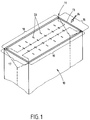
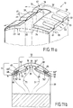
- the two hose ends are each folded into a cross base 11, 12 and, as can be seen from the filling state in FIG. 1, form a rectangular outline of the finished sacks 10 filled with powdery or granular material.
- Sack 10 thus has the shape of a cuboid, apart from rounded corner areas. Both cross floors 11, 12 have different tasks to perform.
- the upper cross bottom 11 also includes a filling valve 13 shown in FIG. 1, in order to fill the material conveyed by air in the sense of the filling arrow 14 into the interior of the bag. Therefore, this cross plate 11 will be referred to as "valve cross plate” in the following.
- the important thing here is to quickly remove the air that enters the inside of the sack from the per se air-impermeable hose without taking the goods with you.
- the other cross plate 12 forms the lower plate during the filling process, onto which the filled product falls.
- This cross base 12 is therefore to be referred to in the following as "stand base”.
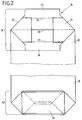
- FIG. 2 shows the valve bag 10 with its two cross-bottom regions 11, 12, specifically in the flat state that is present before the bag is filled.
- the base 12 is already shown in the finished state, while the valve cross base 11 is shown in a first folding phase of the hose 20.
- the folding structure in both cross bases 11, 12 is analog, but different in detail.
- the stand base 12 is designed in a conventional manner and has a cover sheet 15 placed on the finished cross-bottom fold, which is connected over the entire area to the fold layers placed underneath.
- the structure of the cross valve base 11 comprises, starting from the hose 20, the following four folding parts.
- the short narrow sides 16, 17 of the cross base 11 shown in FIG. 1 are formed by the two corner folds 21, 22 shown in FIG. 2, which are folded against one another.
- the two long longitudinal sides 18, 19 of the rectangular outline of the cross base shown in FIG. 1 are formed by two side flaps 23, 24 which are shown in the extended state in FIG. 2 but in the folded state in FIG. 7a.
- the corresponding fold lines 26, 27 which can be seen in FIGS. 2 to 5b are designated by 26 and 27, respectively.
- the front hose wall forms a folded edge 29 in order to produce the one side flap 24, which is still stretched there.
- valve reinforcement sheet 30 is applied, which in the present case is formed in one layer, but could also be formed in multiple layers. As can be seen from FIG. 4, this sheet 30 is folded over at one end and its lower, short fold position 31 is glued in the end area, as can be seen by hatching in FIG. 3, in the area of the two side flaps 23, 24.
- an inwardly or outwardly projecting sleeve-shaped insert could also be used, which then forms the filling valve.
- a filter sheet 40 made of air-permeable material is placed over the two corner inserts 21, 22 and over the inner parts of the two side flaps 23, 24, which is rectangular in shape and only on its two narrow ends 41, 42 is provided with a linear adhesive 43.
- the adhesive 43 extends over the valve reinforcement sheet 30 located on the corner wrap 21.
- the longitudinal edge regions 48, 49 of the filter sheet 40 lying between the two end-side adhesive bonds 43 are completely connection-free, that is to say not connected to the associated side flaps 23 or 24.
- one or a few adhesive dots could be provided, which are identified by a cross in FIG. 5a and designated by 28.
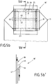
- a micro needling is used, which is illustrated by a dot hatching 25 in Fig. 5a.
- FIG. 5b shows a method stage corresponding to FIG. 5a for forming a valve cross bottom 11 in an alternative configuration of a valve bag 10 '.
- the same process steps are first carried out as previously described for the valve sack 10 according to FIG. 5a, which is why the previous statements apply in this respect. It is enough to only consider the differences.
- the filter sheet 44 which is also rectangular here, has a Z-fold 45 parallel to the mentioned fold lines 26, 27 of the two side flaps 23, 24, which has two Z-fold edges 46, 47 pointing away from each other.
- This filter sheet 44 is also well permeable to air, for which purpose a micro needling 25 is used in the paper producing the filter sheet 44 in this case too. This micro-needling is illustrated by a hatching in the drawings.
- FIGS. 6a and 6b show the method step that follows the method step of FIGS. 5a and 5b, respectively.
- An adhesive application 36 is applied to the two side flaps 23, 24 only in the respective end sections 35.
- the intermediate section 33 and 34, respectively, of the two side flaps 23, 24 remains absolutely adhesive-free.
- FIGS. 7a and 7b result.
- the two side flaps 23, 24 are folded against one another, as a result of which the respective, already mentioned longitudinal sides 18, 19 of the cross base 11 are formed. It is important that the folded side flaps 23, 24 are arranged with their respective longitudinal edges 37, 38 at a free distance 39. This is achieved by a correspondingly narrow width 63, 64 of the two side flaps 23, 24. Therefore, between the two longitudinal edges 37, 38 of the two side flaps 23, 24 there is an exposed central strip 60 of the filter sheet 40. This also applies, as shown in FIG.
- valve bag 10 in an analogous manner to the filter sheet 44 provided with the Z-fold 45 in FIG previous Fig. 6b illustrated alternative. It is decisive that in this valve bag 10 'the two Z-fold edges 46, 47 come to rest in this spacing area 39 between the side flaps 23, 24. This facilitates their final folding, which will be explained later in connection with FIG. 11b.
- a cover sheet 50 or 50 ' serves as the last component for both valve sacks 10, 10', for which, if one takes account of FIG. 11b ', three variants can result.
- the cover sheet 50 is designed according to FIGS. 8a and 9b.
- the single-layer cover sheet 50 is provided with a short fold 51 at the end. Air-permeable material can already be used for the cover sheet 50.
- a central zone 52 of the cover sheet 50 to be described in more detail, is provided with air slots 53 in order to increase the air permeability.
- a frame-shaped adhesive bond 54, 55 is provided, which is provided with interruptions 56.
- the other two edge zones 58 which accompany the two long sides 18, 19, there are short adhesive studs 55, between which there are adhesive-free interruptions 56.
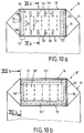
- the central zone 52 which is surrounded on all sides by these adhesive edge zones 57, 58, is free from any bonding and is therefore fully air-permeable. This air permeability will be increased by the air slots 53 already mentioned. These air slots 53 run, as can be seen from FIG. 10 a, transversely to the described cross-floor longitudinal sides 18, 19 and are expediently aligned with the adhesive interruptions 56 of the edge zones 58.
- FIG. 11a The conditions resulting from this sack 10 during the filling process can be seen from Fig. 11a.
- FIG. 11 a the central zone of the cover sheet 50 is shown partly broken away in order to be able to better recognize the conditions at the longitudinal edge zones 58. Due to the outwardly penetrating air, the flow of which is illustrated by dash-dotted arrows 61, an inflating air chamber 70 arises between the central zone 52 of the cover sheet 50 and the free central strip 60 of the filter sheet 40 and the areas of the side flaps 23, 24 which have not yet been connected is vented both through the mentioned air slots 53 shown in FIG. 10a and through outlet channels 59 shown in FIG. 11a.
- These outlet channels 59 result from the interruptions 56 of the adhesive studs 55 along the longitudinal edge zones 58 of the frame-shaped adhesive bond described above.
- These air outlet channels 59 are oriented transversely, that is to say to the longitudinal sides 18, 19 of the valve cross-head 11, which can be seen from FIG. 10a, open.
- the cover sheet 50 'intended for the alternative valve bag 10' has a structure which differs from that of the cover sheet 50 'of the valve bag 10 and is shown in FIGS. 8b, 9b and 9c. Only the differences from the previous cover sheet 50 are described, which is why the previous description applies in all other respects. An essential difference is that - seen in the direction of the longitudinal sides 18, 19 of the cross base 11 shown in FIG. 10b - the cover sheet 50 ' 9b, which has a C-central region 62 between its two C-edge regions 65, 66. The refolding 51 already described in the preceding cover sheet 50 is also present in this alternative 50 ', as can be seen in particular from FIG. 9c.
- FIG. 10b The finished assembly position of this C-shaped cover sheet 50 'is shown in FIG. 10b for the valve bag 10', the preceding process stage of which can be seen from FIG. 7b already described.
- the conditions that arise during the filling process are initially illustrated schematically in FIG. 11b.
- the C-shaped flat fold shape 50 'of the cover sheet present before the filling process is first illustrated.
- the position of the C-fold edges 68 is initially in the region of the longitudinal sides 18, 19 of the hose 20 of the valve cross-base 11. It can be seen that the above-described adhesive strips 55 'on the edge are set back 69 from these original C-fold edges 68.
- the shape of the cover sheet in the position of use during the filling process is illustrated by the solid line 50 ′′ in FIG. 11b.
- an air chamber 70 is formed between the central zone 52 from the cover sheet 50 ′′ by the air pushing outwards, indicated by arrows 71, relative to the filter sheet 44 and the two side flaps 23, 24 in the region of the exposed central sections 33, which can be seen in FIG. 7b. 34 is generated.
- the cover sheet 50 ′′ can bulge out bell-shaped, because the C-fold edges 68 projecting in the initial state in relation to the adhesives 55 ′ of FIG. 11b can roll up, so that now, in the position of use 50 ′′ of the cover sheet, there is an outwardly offset folding point 68 ′′.
- the Z-shaped fold 45 there, according to FIG. 11b can now open in a mushroom shape. This creates an area for the air flow 71 that is enlarged compared to the original sack cross section.
- the air chamber 70 is vented not only by the flow 71 mentioned in the region of the air-permeable central zone 52 of the cover sheet in the position of use 50 ′′, but also by air outlets which can be seen in the direction of the flow arrows 72 in FIG. 12b.
- the bonds 55 'provided on the C-edge region of the cover sheet 50' are on the outer surfaces, which is why their inner surfaces remain free.
- the end-side adhesive bond 54 'shown in FIG. 9c, which is illustrated in FIG. 12b, also leaves the inner surfaces of the C-edge region untouched, which is why longitudinal air outlet ducts 73 in the region of the smooth surface already described in connection with FIG. 9c Edge zone 67 of the cover sheet arise.
- This use position 50 ′′ of the cover sheet can be seen in FIG. 12 b with the bell-shaped central zone 52 and the smooth edge zone 67 provided with longitudinal channels 73.
- Fig. 11b shows an alternative to Fig. 11b. Only the deviations from the measures shown in FIGS. 11b and 12b are to be described, which is why the previous description applies in all other respects. The difference is that here, too, the C-shaped longitudinally profiled cover sheet 75 with its two C-edge regions 76 is not connected to the two side flaps 23, 24 of the cross valve base 11, but to the adjoining hose side wall 74 of the bag 10 '. Here, the analog bonds 55 'are located on the inner surface of the two C-edge regions 76. In other respects, the bell-shaped air chamber 70 described above occurs in the case of use according to FIG. 11b'.
Landscapes
- Engineering & Computer Science (AREA)
- Mechanical Engineering (AREA)
- Bag Frames (AREA)
- Pens And Brushes (AREA)
- Containers And Packaging Bodies Having A Special Means To Remove Contents (AREA)
Applications Claiming Priority (2)
| Application Number | Priority Date | Filing Date | Title |
|---|---|---|---|
| DE19536740 | 1995-10-02 | ||
| DE19536740 | 1995-10-02 |
Publications (2)
| Publication Number | Publication Date |
|---|---|
| EP0767105A1 true EP0767105A1 (fr) | 1997-04-09 |
| EP0767105B1 EP0767105B1 (fr) | 1999-04-14 |
Family
ID=7773861
Family Applications (1)
| Application Number | Title | Priority Date | Filing Date |
|---|---|---|---|
| EP96115638A Expired - Lifetime EP0767105B1 (fr) | 1995-10-02 | 1996-09-30 | Sac à valve à fond croisé ventilé |
Country Status (3)
| Country | Link |
|---|---|
| EP (1) | EP0767105B1 (fr) |
| AT (1) | ATE178860T1 (fr) |
| DE (1) | DE59601648D1 (fr) |
Cited By (10)
| Publication number | Priority date | Publication date | Assignee | Title |
|---|---|---|---|---|
| EP0982238A1 (fr) * | 1998-08-27 | 2000-03-01 | Wacker-Chemie GmbH | Conteneur souple pour des produits solides hautement dispersés et aérés et procédé pour le remplissage du produit |
| WO2001054995A1 (fr) * | 2000-01-28 | 2001-08-02 | Upm-Kymmene Corporation | Sac a valve et procede de fabrication |
| US6986605B1 (en) | 2003-04-23 | 2006-01-17 | Exopack-Technology, Llc | Multiwall vented bag, vented bag forming apparatus, and associated methods |
| EP1914173A1 (fr) * | 2006-10-20 | 2008-04-23 | Mondi Packaging AG | Sac à valve |
| WO2010116198A1 (fr) * | 2009-04-08 | 2010-10-14 | Mandzsu Zoltan | Sac à valve et procédé de remplissage correspondant |
| WO2011051739A1 (fr) * | 2009-10-26 | 2011-05-05 | Mandzsu Zoltan | Récipient d'emballage amélioré avec relief de surpression, procédé d'emballage et système |
| WO2012025413A3 (fr) * | 2010-08-25 | 2012-05-10 | Windmöller & Hölscher Kg | Sac, procédé et dispositif de fabrication de sacs |
| DE202017001357U1 (de) * | 2017-03-13 | 2018-06-14 | Dy-Pack Verpackungen Gustav Dyckerhoff Gmbh | Mehrlagiger Ventilsack |
| WO2019232603A1 (fr) * | 2018-06-05 | 2019-12-12 | Klabin S.A. | Agencement de construction dans un sac en papier |
| CN112572980A (zh) * | 2020-12-22 | 2021-03-30 | 上海艾录包装股份有限公司 | 一种全自动上袋的阀口袋 |
Families Citing this family (2)
| Publication number | Priority date | Publication date | Assignee | Title |
|---|---|---|---|---|
| DE202010000042U1 (de) | 2010-01-14 | 2010-06-02 | Papiersackfabrik Tenax Gmbh & Co. Kg | Ventilsack mit Entlüftungsvorrichtung |
| DE202013102644U1 (de) | 2013-06-19 | 2013-07-24 | Papiersackfabrik Tenax Gmbh & Co. Kg | Ventilsack mit Entlüftungsvorrichtungen |
Citations (3)
| Publication number | Priority date | Publication date | Assignee | Title |
|---|---|---|---|---|
| DE1085027B (de) * | 1958-04-16 | 1960-07-07 | Bischof & Klein Papierverarbei | Ventilsack aus Papier oder aus einem aehnlichen Werkstoff |
| DE1586779A1 (de) * | 1967-09-16 | 1971-05-19 | Hans Lissner | Kunststoffsack mit unter Bildung von dreieckfoermigen symmetrischen Eckeinschlaegen hergestelltem Boden wie Verfahren zur Herstellung eines solchen Sackes |
| US3989182A (en) * | 1976-02-12 | 1976-11-02 | Great Plains Bag Corporation | Vented bag |
-
1996
- 1996-09-30 DE DE59601648T patent/DE59601648D1/de not_active Expired - Lifetime
- 1996-09-30 AT AT96115638T patent/ATE178860T1/de not_active IP Right Cessation
- 1996-09-30 EP EP96115638A patent/EP0767105B1/fr not_active Expired - Lifetime
Patent Citations (3)
| Publication number | Priority date | Publication date | Assignee | Title |
|---|---|---|---|---|
| DE1085027B (de) * | 1958-04-16 | 1960-07-07 | Bischof & Klein Papierverarbei | Ventilsack aus Papier oder aus einem aehnlichen Werkstoff |
| DE1586779A1 (de) * | 1967-09-16 | 1971-05-19 | Hans Lissner | Kunststoffsack mit unter Bildung von dreieckfoermigen symmetrischen Eckeinschlaegen hergestelltem Boden wie Verfahren zur Herstellung eines solchen Sackes |
| US3989182A (en) * | 1976-02-12 | 1976-11-02 | Great Plains Bag Corporation | Vented bag |
Cited By (14)
| Publication number | Priority date | Publication date | Assignee | Title |
|---|---|---|---|---|
| US6199602B1 (en) | 1998-08-27 | 2001-03-13 | Wacker-Chemie Gmbh | Large drums for high-dispersion, high air content solids, and a method for filling them |
| EP0982238A1 (fr) * | 1998-08-27 | 2000-03-01 | Wacker-Chemie GmbH | Conteneur souple pour des produits solides hautement dispersés et aérés et procédé pour le remplissage du produit |
| WO2001054995A1 (fr) * | 2000-01-28 | 2001-08-02 | Upm-Kymmene Corporation | Sac a valve et procede de fabrication |
| US6986605B1 (en) | 2003-04-23 | 2006-01-17 | Exopack-Technology, Llc | Multiwall vented bag, vented bag forming apparatus, and associated methods |
| RU2429174C2 (ru) * | 2006-10-20 | 2011-09-20 | Монди Аг | Клапанный мешок |
| EP1914173A1 (fr) * | 2006-10-20 | 2008-04-23 | Mondi Packaging AG | Sac à valve |
| WO2010116198A1 (fr) * | 2009-04-08 | 2010-10-14 | Mandzsu Zoltan | Sac à valve et procédé de remplissage correspondant |
| WO2011051739A1 (fr) * | 2009-10-26 | 2011-05-05 | Mandzsu Zoltan | Récipient d'emballage amélioré avec relief de surpression, procédé d'emballage et système |
| WO2012025413A3 (fr) * | 2010-08-25 | 2012-05-10 | Windmöller & Hölscher Kg | Sac, procédé et dispositif de fabrication de sacs |
| US9205957B2 (en) | 2010-08-25 | 2015-12-08 | Windmoeller & Hoelscher Kg | Sack and method and device for producing sacks |
| DE202017001357U1 (de) * | 2017-03-13 | 2018-06-14 | Dy-Pack Verpackungen Gustav Dyckerhoff Gmbh | Mehrlagiger Ventilsack |
| WO2018166833A1 (fr) * | 2017-03-13 | 2018-09-20 | Dy-Pack Verpackungen Gustav Dyckerhoff Gmbh | Sac à valve multicouche |
| WO2019232603A1 (fr) * | 2018-06-05 | 2019-12-12 | Klabin S.A. | Agencement de construction dans un sac en papier |
| CN112572980A (zh) * | 2020-12-22 | 2021-03-30 | 上海艾录包装股份有限公司 | 一种全自动上袋的阀口袋 |
Also Published As
| Publication number | Publication date |
|---|---|
| DE59601648D1 (de) | 1999-05-20 |
| ATE178860T1 (de) | 1999-04-15 |
| EP0767105B1 (fr) | 1999-04-14 |
Similar Documents
| Publication | Publication Date | Title |
|---|---|---|
| EP1858769B1 (fr) | Sachet en papier | |
| DE2254640C3 (de) | Flach zusammenlegbarer Beutel | |
| CH687693A5 (de) | Verfahren zum Herstellen eines mit einem Schuettgut fuellbaren, im Leerzustand flachen Packmittel sowie Vorrichtung zum Verschliessen eines nach demV erfahren hergestellten Packungsmittels. | |
| EP2608954B1 (fr) | Sac et procédé de fabrication de sacs | |
| EP0264519B1 (fr) | Sachet à fond croisé avec valve | |
| EP0767105B1 (fr) | Sac à valve à fond croisé ventilé | |
| EP1910176B1 (fr) | Sac pouvant etre aere | |
| DE102016012300A1 (de) | Zigarettenpackung sowie Verfahren und Vorrichtung zum Herstellen derselben | |
| EP3606835B1 (fr) | Sac multi-couches et procédé de fabrication d'un sac multi-couches | |
| EP3541717B1 (fr) | Sac à valve multicouche | |
| DE102019100193A1 (de) | Mehrlagiger Sack | |
| EP2345595A1 (fr) | Sac d'aération doté d'un dispositif d'aération | |
| DE69814470T2 (de) | Geschlossener sack mit luftaustritt | |
| DE202021106636U1 (de) | Papierventilsäcke mit nicht-kontinuierlicher Längsnahtklebung | |
| EP0498047B1 (fr) | Sachet à fond croisé ou plat avec valve | |
| DE1486238C3 (de) | Mehrlagiger Kreuzbodensack | |
| DE4021801A1 (de) | Sack oder beutel mit im gefuellten zustand rechteckigem boden und angeklebtem griffteil | |
| EP3107816B1 (fr) | Sac | |
| CH644304A5 (de) | Verfahren zum herstellen von mit kreuzboeden versehenen saecken. | |
| DE202021106637U1 (de) | Papierventilsäcke mit nicht-verklebter Sperrschicht | |
| DE4140213A1 (de) | Ventilsack mit entlueftungsventil | |
| DE1436838A1 (de) | Schlauchfoermige Ventileinlage fuer Ventilsaecke | |
| DE1802854B2 (de) | Mehrlagiger Ventilsack | |
| DE2832256C2 (fr) | ||
| DE102017001760A1 (de) | Mehrlagiger Sack |
Legal Events
| Date | Code | Title | Description |
|---|---|---|---|
| PUAI | Public reference made under article 153(3) epc to a published international application that has entered the european phase |
Free format text: ORIGINAL CODE: 0009012 |
|
| AK | Designated contracting states |
Kind code of ref document: A1 Designated state(s): AT DE FR GB IT SE |
|
| 17P | Request for examination filed |
Effective date: 19970221 |
|
| GRAG | Despatch of communication of intention to grant |
Free format text: ORIGINAL CODE: EPIDOS AGRA |
|
| 17Q | First examination report despatched |
Effective date: 19980714 |
|
| GRAG | Despatch of communication of intention to grant |
Free format text: ORIGINAL CODE: EPIDOS AGRA |
|
| GRAH | Despatch of communication of intention to grant a patent |
Free format text: ORIGINAL CODE: EPIDOS IGRA |
|
| GRAH | Despatch of communication of intention to grant a patent |
Free format text: ORIGINAL CODE: EPIDOS IGRA |
|
| GRAA | (expected) grant |
Free format text: ORIGINAL CODE: 0009210 |
|
| AK | Designated contracting states |
Kind code of ref document: B1 Designated state(s): AT DE FR GB IT SE |
|
| REF | Corresponds to: |
Ref document number: 178860 Country of ref document: AT Date of ref document: 19990415 Kind code of ref document: T |
|
| ET | Fr: translation filed | ||
| ITF | It: translation for a ep patent filed | ||
| REF | Corresponds to: |
Ref document number: 59601648 Country of ref document: DE Date of ref document: 19990520 |
|
| GBT | Gb: translation of ep patent filed (gb section 77(6)(a)/1977) |
Effective date: 19990504 |
|
| PLBE | No opposition filed within time limit |
Free format text: ORIGINAL CODE: 0009261 |
|
| STAA | Information on the status of an ep patent application or granted ep patent |
Free format text: STATUS: NO OPPOSITION FILED WITHIN TIME LIMIT |
|
| 26N | No opposition filed | ||
| REG | Reference to a national code |
Ref country code: GB Ref legal event code: IF02 |
|
| PGFP | Annual fee paid to national office [announced via postgrant information from national office to epo] |
Ref country code: GB Payment date: 20060821 Year of fee payment: 11 |
|
| PGFP | Annual fee paid to national office [announced via postgrant information from national office to epo] |
Ref country code: FR Payment date: 20060919 Year of fee payment: 11 |
|
| PGFP | Annual fee paid to national office [announced via postgrant information from national office to epo] |
Ref country code: AT Payment date: 20060920 Year of fee payment: 11 |
|
| PGFP | Annual fee paid to national office [announced via postgrant information from national office to epo] |
Ref country code: IT Payment date: 20060930 Year of fee payment: 11 |
|
| PGFP | Annual fee paid to national office [announced via postgrant information from national office to epo] |
Ref country code: SE Payment date: 20060918 Year of fee payment: 11 |
|
| GBPC | Gb: european patent ceased through non-payment of renewal fee |
Effective date: 20070930 |
|
| EUG | Se: european patent has lapsed | ||
| PG25 | Lapsed in a contracting state [announced via postgrant information from national office to epo] |
Ref country code: AT Free format text: LAPSE BECAUSE OF NON-PAYMENT OF DUE FEES Effective date: 20070930 |
|
| REG | Reference to a national code |
Ref country code: FR Ref legal event code: ST Effective date: 20080531 |
|
| PG25 | Lapsed in a contracting state [announced via postgrant information from national office to epo] |
Ref country code: SE Free format text: LAPSE BECAUSE OF NON-PAYMENT OF DUE FEES Effective date: 20071001 Ref country code: FR Free format text: LAPSE BECAUSE OF NON-PAYMENT OF DUE FEES Effective date: 20071001 |
|
| PG25 | Lapsed in a contracting state [announced via postgrant information from national office to epo] |
Ref country code: GB Free format text: LAPSE BECAUSE OF NON-PAYMENT OF DUE FEES Effective date: 20070930 |
|
| PG25 | Lapsed in a contracting state [announced via postgrant information from national office to epo] |
Ref country code: IT Free format text: LAPSE BECAUSE OF NON-PAYMENT OF DUE FEES Effective date: 20070930 |
|
| PGFP | Annual fee paid to national office [announced via postgrant information from national office to epo] |
Ref country code: DE Payment date: 20091002 Year of fee payment: 14 |
|
| REG | Reference to a national code |
Ref country code: DE Ref legal event code: R119 Ref document number: 59601648 Country of ref document: DE Effective date: 20110401 |
|
| PG25 | Lapsed in a contracting state [announced via postgrant information from national office to epo] |
Ref country code: DE Free format text: LAPSE BECAUSE OF NON-PAYMENT OF DUE FEES Effective date: 20110401 |