EP0767120A2 - Dispositif de guidage de feuilles pour margeur de feuilles - Google Patents
Dispositif de guidage de feuilles pour margeur de feuilles Download PDFInfo
- Publication number
- EP0767120A2 EP0767120A2 EP96114923A EP96114923A EP0767120A2 EP 0767120 A2 EP0767120 A2 EP 0767120A2 EP 96114923 A EP96114923 A EP 96114923A EP 96114923 A EP96114923 A EP 96114923A EP 0767120 A2 EP0767120 A2 EP 0767120A2
- Authority
- EP
- European Patent Office
- Prior art keywords
- sheet
- sheet guiding
- guiding device
- band
- elements
- Prior art date
- Legal status (The legal status is an assumption and is not a legal conclusion. Google has not performed a legal analysis and makes no representation as to the accuracy of the status listed.)
- Granted
Links
- 238000012545 processing Methods 0.000 claims abstract description 27
- 238000004804 winding Methods 0.000 claims abstract description 26
- 239000000463 material Substances 0.000 claims description 3
- 239000011248 coating agent Substances 0.000 claims description 2
- 238000000576 coating method Methods 0.000 claims description 2
- 230000007423 decrease Effects 0.000 claims 1
- 239000013013 elastic material Substances 0.000 claims 1
- 238000012546 transfer Methods 0.000 abstract description 20
- 238000007639 printing Methods 0.000 abstract description 4
- 230000000630 rising effect Effects 0.000 abstract description 2
- 238000011161 development Methods 0.000 description 5
- 239000000969 carrier Substances 0.000 description 2
- 238000013016 damping Methods 0.000 description 2
- 238000013461 design Methods 0.000 description 2
- 239000004033 plastic Substances 0.000 description 2
- 229920003023 plastic Polymers 0.000 description 2
- 229910000831 Steel Inorganic materials 0.000 description 1
- 238000005299 abrasion Methods 0.000 description 1
- 238000010276 construction Methods 0.000 description 1
- 238000011109 contamination Methods 0.000 description 1
- 230000001419 dependent effect Effects 0.000 description 1
- 239000000835 fiber Substances 0.000 description 1
- 238000009434 installation Methods 0.000 description 1
- 238000012423 maintenance Methods 0.000 description 1
- 238000000034 method Methods 0.000 description 1
- 229920001296 polysiloxane Polymers 0.000 description 1
- 239000005871 repellent Substances 0.000 description 1
- 238000000926 separation method Methods 0.000 description 1
- 238000004904 shortening Methods 0.000 description 1
- 239000010959 steel Substances 0.000 description 1
Images

Classifications
-
- B—PERFORMING OPERATIONS; TRANSPORTING
- B65—CONVEYING; PACKING; STORING; HANDLING THIN OR FILAMENTARY MATERIAL
- B65H—HANDLING THIN OR FILAMENTARY MATERIAL, e.g. SHEETS, WEBS, CABLES
- B65H3/00—Separating articles from piles
- B65H3/66—Article guides or smoothers, e.g. movable in operation
- B65H3/68—Article guides or smoothers, e.g. movable in operation immovable in operation
-
- B—PERFORMING OPERATIONS; TRANSPORTING
- B65—CONVEYING; PACKING; STORING; HANDLING THIN OR FILAMENTARY MATERIAL
- B65H—HANDLING THIN OR FILAMENTARY MATERIAL, e.g. SHEETS, WEBS, CABLES
- B65H3/00—Separating articles from piles
- B65H3/08—Separating articles from piles using pneumatic force
- B65H3/0808—Suction grippers
- B65H3/0816—Suction grippers separating from the top of pile
- B65H3/0825—Suction grippers separating from the top of pile and acting on the rear part of the articles relatively to the final separating direction
-
- B—PERFORMING OPERATIONS; TRANSPORTING
- B65—CONVEYING; PACKING; STORING; HANDLING THIN OR FILAMENTARY MATERIAL
- B65H—HANDLING THIN OR FILAMENTARY MATERIAL, e.g. SHEETS, WEBS, CABLES
- B65H5/00—Feeding articles separated from piles; Feeding articles to machines
- B65H5/36—Article guides or smoothers, e.g. movable in operation
- B65H5/38—Article guides or smoothers, e.g. movable in operation immovable in operation
-
- B—PERFORMING OPERATIONS; TRANSPORTING
- B65—CONVEYING; PACKING; STORING; HANDLING THIN OR FILAMENTARY MATERIAL
- B65H—HANDLING THIN OR FILAMENTARY MATERIAL, e.g. SHEETS, WEBS, CABLES
- B65H2404/00—Parts for transporting or guiding the handled material
- B65H2404/60—Other elements in face contact with handled material
- B65H2404/69—Other means designated for special purpose
- B65H2404/691—Guiding means extensible in material transport direction
- B65H2404/6911—Guiding means extensible in material transport direction by unwinding from storage section
-
- B—PERFORMING OPERATIONS; TRANSPORTING
- B65—CONVEYING; PACKING; STORING; HANDLING THIN OR FILAMENTARY MATERIAL
- B65H—HANDLING THIN OR FILAMENTARY MATERIAL, e.g. SHEETS, WEBS, CABLES
- B65H2511/00—Dimensions; Position; Numbers; Identification; Occurrences
- B65H2511/10—Size; Dimensions
- B65H2511/12—Width
-
- B—PERFORMING OPERATIONS; TRANSPORTING
- B65—CONVEYING; PACKING; STORING; HANDLING THIN OR FILAMENTARY MATERIAL
- B65H—HANDLING THIN OR FILAMENTARY MATERIAL, e.g. SHEETS, WEBS, CABLES
- B65H2511/00—Dimensions; Position; Numbers; Identification; Occurrences
- B65H2511/20—Location in space
- B65H2511/22—Distance
Definitions
- the invention relates to a sheet guiding device for a feed area of a sheet processing machine, in particular a printing machine, which guides the sheet after separation from a stack of feeders.
- a suction conveyor device which comprises lifting and dragging suction devices.
- the top sheet is separated from a stack by the suction cups sucking the sheet in a lower position and then lifting the suction cups.
- blow blowers from the trailing edge of the stack blow air under the sheet to assist in separating the sheet from the stack and lifting the sheet, while side air blowers continuously maintain air against the stack side edges in the leading to maintain air pressure Blow section of the bow.
- horizontal reciprocating suction cups drag suction cups
- the conveyors then transport the sheet by horizontal movement in the direction of the sheet-processing machine, so that the leading section of the sheet arrives at a transfer point on sheet transport devices of the downstream sheet-processing machine, for example via conveyor belts guided over a feed table.
- the take-over by the sheet transport device of the sheet-processing machine takes place by clocked lowering of the clock rollers, whereby the sheet is transferred to the circulating conveyor belts is pressed.
- the suction air supply to the suction devices is interrupted and the suction devices are brought into their rear position in the sheet conveying direction.
- sheet guiding devices are used above the sheet conveying path. Such a sheet guide device is known from DE 17 86 232 A1.
- the sheet In the feed area of a sheet feed device, the sheet is guided on its upper side on the sheet conveying path above the sheet stack by a plurality of horizontally arranged, telescopically elongated sheet guide rods.
- the telescopic rods run horizontally in one plane from a traverse, arranged in the sheet transport direction behind the suction head, transversely to the sheet transport direction and connected to the suction head, above the sheet stack up to the transfer point to a feed table of a printing machine.
- the above sheet guide rods With a format-dependent adjustment of the suction head in or against the sheet transport direction, the above sheet guide rods are pushed together.
- the tubular sections of the arc guide rods form sections that run in steps.
- the guide elements are essentially dimensionally stable. A major disadvantage is that the sheet guiding elements have to be maintained in order to maintain their functional reliability, since the telescopic rods are exposed to increasing wear and tear due to contamination and abrasion.
- the object of the invention is to provide a sheet guiding device which guides sheets safely and without damage in the feed area of sheet-processing machines, in particular printing machines, and is adjustable both to the longitudinal sheet format and to the horizontal sheet format.
- An advantage of the invention is that the sheet guiding elements can be adjusted not only in the longitudinal direction of the sheet, but also in the transverse direction of the sheet, so that the lateral format adjustment of devices, e.g. lateral stacking stops or side loosening blowers, is not hindered by the sheet guiding device and nevertheless sheet guidance over the entire sheet width.
- Another advantage of the invention is that stepless guide devices are created with low friction. Because the guide elements are under tension, they exert a damping, downward force on the transported sheet. This prevents damage to the top of the sheet, especially when sheets already printed are reinstalled.
- the sheet guide elements according to the invention have the advantage that they are extremely low-maintenance.
- the design of the guide elements made of stretchable material makes it possible to dispense with winding rolls, so that an extremely simple and space-saving construction is achieved with the same functionality compared to essentially non-elastic tapes with a winding roll.
- An advantage of the development of the invention is a fastening of the sheet guiding elements or the winding rollers to the holders on which the side stacking stops and / or side loosening blowers are attached. By this measure, who the sheet guide devices easily any format adjustment adapted so that both the side stack stops and the sheet guide device are carried out in a common operation. This is particularly advantageous in the case of fully automatic adjustment of the lateral stacking stops and loosening blowers etc.
- the sheet guiding device is inclined in relation to the top of the stack in the sheet transport direction. This ensures that the sheets are guided exactly to the transfer point of a transport roller arranged downstream.
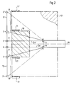
- FIG. 1 shows the invention in side view and FIG. 2 shows a schematic illustration of the invention in top view.
- a sheet is separated in a known manner from a sheet stack 10, 10 'and transported in the direction of a sheet processing machine by means of a suction conveyor 4. During transport, the top of the sheet is guided in a region between a transfer point and drag suction devices 4b by means of a sheet guiding device 1.
- the point of transfer here is the point at which the clock rollers 5 are placed on the sheet in the region of leading sheet edge of the sheet is brought into contact with sheet conveyor belts 9 and thus the transfer to the sheet processing machine takes place.
- the sheet guiding device 1 has several, for example four, sheet guiding elements 2 arranged next to one another, but fewer or more sheet guiding elements can also be used if required.
- the sheet guide elements 2 are each formed from a combination of a band-shaped body 2a and a winding roll 2b, on which one end of the band-shaped body 2a is fastened.
- the band-shaped body 2a is a band, a rope or a cord consisting of steel, plastic, natural fibers or a similar material.
- the winding roll 2b is designed to be self-winding in that it is acted upon in a known direction in a direction of rotation by a restoring force, for example by means of a spiral spring. The winding direction results from the direction in which the restoring force acts on the winding roll.
- the sheet guide elements 2 are attached to the free end of the band-shaped body 2a on the front lower edge of the suction conveyor 4, as viewed in the sheet transport direction T, and at the other end the winding rollers 2b are attached to brackets 3 which face the sheet-processing machine the device are attached.
- the winding rolls 2b are attached to the holders 3 directly above the sheet transport path.
- the band-shaped bodies 2a between the winding roller 2b and the attachment at the free end on the side of the suction conveyor 4 are provided via additional deflection elements 3a to 12 fixedly attached to the holders 3 deflected directly via the sheet transport path.
- An adjustment to sheet format is carried out on the brackets 3, which are arranged in the format adjustment areas.
- Form adjustment range denotes the sections AC and BD between points A and B, respectively, which are close to the lateral sheet edges with the maximum sheet landscape format, and points C and D, which are in the vicinity of the lateral sheet edges with a minimal sheet landscape format, and in which the lateral sheet stops 11 are made against the feeder stack 10 by methods transverse to the sheet transport direction T.
- the brackets 3, which are arranged in the format adjustment area (AC, BD), are placed transversely to the sheet transport direction so far to the machine center M that they run over the area of the corners of the leading edge of the sheet to be fed, if this is at the transfer point.
- a traverse 12 is provided at right angles to the sheet transport direction T between the side parts of the sheet feeding device.
- the brackets 3, which are arranged in the format adjustment areas AC, BD, are slidably mounted on the cross member 12 transversely to the sheet transport direction T between points A and C or B and D in accordance with the sheet transverse format.
- the brackets 3, which are arranged in the middle between the format adjustment areas AC, BD, are not adjusted.
- the length of the band-shaped body 2a is selected such that when the suction conveyor 4 and the holders 3 arranged in the format adjustment ranges AC, BD are set to the minimum sheet format, they are unwound from the winding roll 2b that the restoring force of the winding rollers 2b acts on the band-shaped body 2a.
- the sheet guide elements 2 are fastened to the holders 3 behind the sheet transfer point U.
- the sheet guide elements 2 are carried out under the rotatable clock roller shaft 7, on which the clock rollers 5 are fastened by means of carriers 6, beyond the transfer point. Because the distance of the front edge of the suction conveyor 4, to which the sheet guide elements 2 are attached, facing the sheet processing machine is greater than the distance of the clock roller shaft 7 from the top of the sheet stack 10, the sheet guide elements 2 are inclined in the sheet transport direction T, through which the sheet guide device 1 and the top of the sheet stack 10 converge in a funnel shape in the side view. As a result, the leading edge of the sheet being transported or the sheet stream is reliably guided to the transfer point U.
- the band-shaped bodies 2a are provided with a coating or sheathing, for example made of silicone or plastics, which has little friction with the surface of the sheet to be transported and / or is color-repellent.
- brackets 3 like the other brackets 3 adjustable transversely to the sheet transport direction T on the cross member 12 in order to change the distances between the sheet guide elements 2 depending on the rigidity of the sheet to be fed.
- This also ensures that the adjustment range, in which the carrier 6 can be moved with clock rollers 5 transversely to the sheet transport direction T, is not limited by the brackets 3.
- the adjustment can be carried out manually or automatically by means of a separate drive device for the brackets arranged between the format adjustment areas AC, BD.
- brackets 3 are the side stack stops 11 or the means used to which the side stacking stops 11 are attached and with which the side stacking stops 11, 11 'are adjusted transversely to the sheet transport direction in the format adjustment range AC, BD. In this way, the guide elements 2 follow the lateral stacking stops 11 in one operation and always cover the entire sheet width.
- extensions 8 which are mounted vertically on the front edge of the suction conveyor 4, deflect the sheet guiding elements to a certain distance from the level of the top of the stack. These are preferably adjustable in the vertical direction in order to be able to vary the inclination of the sheet guiding elements from the holder 3 to the suction conveyor 4 depending on the behavior of the sheets to be fed. To reduce the Friction between these extensions 8 and the sheet guide elements 2 carry the extensions 8 at their lower end rollers 8a.
- deflection elements in the form of open hooks or closed eyes are provided on the holders 3 and / or the suction conveyor 4, through which a band-shaped body 2 a from the winding roller via the suction conveyor 4 to a further holder 3 on the sheet processing machine-facing side is returned, for example from point E via point G on the front edge of the suction conveyor 4 at point A and from point F via point H at point B.
- a sheet guiding element 2 can be positioned several times between the suction conveyor 4 and the holders 3 alternately zigzag back and forth.
- the sheet guiding elements can be attached to the suction conveyor or the holders 3 at one or both ends by forming hook elements on the holders and loops or hooks or knots on the sheet guiding elements.
- two winding rollers (2b) can also be provided for each of the band-shaped bodies 2a, on each of which one end of the band-shaped body 2a is fastened. Furthermore, it is possible to fasten more than one band-shaped body 2a on a common winding roll 2b, provided that all of the band-shaped bodies 2a in question have the same length or are arranged in such a way that they are lengthened or shortened in the same ratio when the format is changed.
- An alternative solution consists in passing the described band-shaped bodies 2a with winding rollers 2b to replace highly elastic sheet guide elements 2.
- highly elastic sheet guiding elements sheet guiding elements 2, which are used as rubber bands, springs or the like. are executed.
- roll rolls 2b is unnecessary. Further design changes compared to the embodiment described above are not necessary for the function of the invention.
- the sheet guiding device 1 is adjusted in accordance with the format of the sheets to be fed in such a way that the sheet guiding elements 2 arranged in the format adjustment areas extend over the area of the corners of the leading sheet edge of the sheet when it is at the transfer point, so that the sheet is in the area of the leading sheet edge before the transfer point Ü to the sheet processing machine over the entire width.
- the sheet guiding elements 2 arranged in the section BD, between the format adjustment areas AC, BD are adjusted in accordance with the sheet behavior. If they are attached to the carriers 6 of the clock rollers 5, they follow their adjustment.
- the sheet flying up or fluttering through the separating air supplied from the trailing edge of the sheet stack is held down by the sheet guiding elements 2 with a damping force in that the band-shaped bodies 2a are under tension.
- the inclination of the sheet guiding elements 2 minimizes the distance over which the sheet lies against the sheet guiding elements, since the sheet only comes into contact with the sheet guiding elements 2 in the central region of the sheet guiding elements 2.
- the sheet rising or bulging during transport does not come into contact with the sheet guide elements 2 directly behind the suction conveyor device 4 but only at a certain distance from the suction conveyor device 4 is pushed in its rear end region, the upper side of the sheet slides along the sheet guiding elements 2 and is guided by the inclination of the sheet guiding elements in the immediate vicinity of the transfer point U to the sheet-processing machine. While the first sheet comes into direct contact with the sheet guide elements 2 over its entire length, the following sheets touch the sheet guide elements 2 only in the trailing section of the sheet surface due to the scaled feed.
- the sheet guiding elements 2 designed according to the invention compensate for the adjustment of the suction conveyor 4 (in the sheet transport direction T) and the holders 3 or when the sheet guiding elements 2 to be adjusted are attached to the side stacking stops 11 (orthogonal to the sheet transport direction T) in the format adjustment areas AC and BD. If the suction conveyor 4 is adjusted to sheet format in the sheet transport direction, the sheet guide elements 2 are shortened in accordance with the adjustment by the winding rollers 2b winding up the band-shaped bodies 2a due to the restoring force.
- the suction conveyor 4 is adjusted to a larger sheet format against the sheet transport direction T, the sheet guiding elements 2 become longer in that the band-shaped bodies 2a are unwound from the above-mentioned winding rollers 2b against the restoring force.
- this is Elongation or shortening of the sheet guide elements 2 different relative to the way of adjustment of the suction conveyor 4.
- the sheet stops 11, 11 ' are adjusted transversely to the sheet transport direction T, the above-mentioned holders 3 between the points A and C or B and D are adjusted to the same extent.
- the adjustment paths AC and BD result.
- the winding rollers 2b compensate for the adjustment path as described above.
- the suction conveyor 4 moves forward in the sheet transport direction T depending on the sheet longitudinal format and the side sheet stops 11, 11 'together. This shortens all sheet guide elements 2 while maintaining their tension.
- the sheet guide elements 2 are shortened by the reverse movement of the suction conveyor 4 and the lateral stacking stops 11, 11 '.
- the sheet guide elements 2 are shortened by adjusting the clock rollers 5 or the carrier 6 carrying them transversely to the sheet conveying direction T on a crossbar 12, for example in pressure-free areas of sheets already printed on the top, the sheet guide elements 2 follow the adjustment without further ado.
- the sheet guiding device 1 can be brought out of a working position, for example when sheets of high rigidity are applied, by unhooking the band-shaped bodies 2 from the described guide devices or hook-shaped fastenings on the holders 3 or the suction conveyor device 4.
- the inclination of the sheet guide elements 2 is varied in the vertical direction by the adjustment of the holders 8 on the side of the suction conveyor 4.
Landscapes
- Engineering & Computer Science (AREA)
- Mechanical Engineering (AREA)
- Separation, Sorting, Adjustment, Or Bending Of Sheets To Be Conveyed (AREA)
- Feeding Of Articles By Means Other Than Belts Or Rollers (AREA)
Applications Claiming Priority (2)
| Application Number | Priority Date | Filing Date | Title |
|---|---|---|---|
| DE19537284 | 1995-10-06 | ||
| DE19537284A DE19537284C1 (de) | 1995-10-06 | 1995-10-06 | Bogenleiteinrichtung für Bogenanleger |
Publications (3)
| Publication Number | Publication Date |
|---|---|
| EP0767120A2 true EP0767120A2 (fr) | 1997-04-09 |
| EP0767120A3 EP0767120A3 (fr) | 1997-11-05 |
| EP0767120B1 EP0767120B1 (fr) | 2000-12-27 |
Family
ID=7774213
Family Applications (1)
| Application Number | Title | Priority Date | Filing Date |
|---|---|---|---|
| EP96114923A Expired - Lifetime EP0767120B1 (fr) | 1995-10-06 | 1996-09-18 | Dispositif de guidage de feuilles pour margeur de feuilles |
Country Status (4)
| Country | Link |
|---|---|
| US (1) | US5863037A (fr) |
| EP (1) | EP0767120B1 (fr) |
| JP (1) | JPH09124181A (fr) |
| DE (2) | DE19537284C1 (fr) |
Families Citing this family (10)
| Publication number | Priority date | Publication date | Assignee | Title |
|---|---|---|---|---|
| DE19728076C2 (de) * | 1997-01-22 | 2003-09-11 | Roland Man Druckmasch | Bogenanleger |
| DE19713919C1 (de) * | 1997-04-04 | 1998-07-02 | Kba Planeta Ag | Bogenleiteinrichtung für Bogenanleger |
| DE19724733C2 (de) * | 1997-06-12 | 2001-10-04 | Roland Man Druckmasch | Bogenzuführeinrichtung |
| DE19856243A1 (de) * | 1997-12-20 | 1999-06-24 | Heidelberger Druckmasch Ag | Vorrichtung zur Luftversorgung von linear angetriebenen Hub- und/oder Fördermitteln einer Bogen verarbeitenden Maschine |
| ATE259329T1 (de) * | 1999-02-05 | 2004-02-15 | Ferag Ag | Vorrichtung zum abbauen eines stapels von flächigen gegenständen, insbesondere druckereierzeugnissen |
| JP2005041202A (ja) | 2003-07-24 | 2005-02-17 | Heidelberger Druckmas Ag | 印刷技術的な機械内で枚葉紙を搬送するための装置 |
| TWI241241B (en) * | 2003-10-13 | 2005-10-11 | Bobst Sa | Blank diecutting machine |
| DE102005046685A1 (de) * | 2005-09-29 | 2007-04-05 | Heidelberger Druckmaschinen Ag | Bogenleiteinrichtung für Bogenanleger |
| DE102006039986A1 (de) * | 2006-08-25 | 2008-02-28 | Koenig & Bauer Aktiengesellschaft | Bogenleiteinrichtung für Bogenanleger |
| DE102021111315A1 (de) | 2021-05-03 | 2022-11-03 | Koenig & Bauer Ag | Vorrichtung und Verfahren zum Vereinzeln von flächenförmigen Gütern und zum Zuführen zu einer Bearbeitungseinheit |
Family Cites Families (5)
| Publication number | Priority date | Publication date | Assignee | Title |
|---|---|---|---|---|
| GB190007503A (en) * | 1900-04-23 | 1900-06-02 | Thomas King Muir | A New or Improved Filling for the Interstices existing Between Paving Blocks. |
| US2156139A (en) * | 1936-11-17 | 1939-04-25 | Backhouse Headley Townsend | Sheet feeding machine |
| US3482833A (en) * | 1967-09-25 | 1969-12-09 | Miller Printing Machinery Co | Sheet feeder assembly |
| DD261573A1 (de) * | 1987-05-29 | 1988-11-02 | Polygraph Leipzig | Bogenleiteinrichtung in bogenanlegern |
| DD271679A1 (de) * | 1988-05-02 | 1989-09-13 | Polygraph Leipzig | Bogenfuehrung in bogenanlegern |
-
1995
- 1995-10-06 DE DE19537284A patent/DE19537284C1/de not_active Expired - Fee Related
-
1996
- 1996-09-18 DE DE59606251T patent/DE59606251D1/de not_active Expired - Lifetime
- 1996-09-18 EP EP96114923A patent/EP0767120B1/fr not_active Expired - Lifetime
- 1996-10-07 US US08/726,813 patent/US5863037A/en not_active Expired - Lifetime
- 1996-10-07 JP JP8265834A patent/JPH09124181A/ja active Pending
Also Published As
| Publication number | Publication date |
|---|---|
| DE19537284C1 (de) | 1996-10-24 |
| JPH09124181A (ja) | 1997-05-13 |
| DE59606251D1 (de) | 2001-02-01 |
| EP0767120A3 (fr) | 1997-11-05 |
| US5863037A (en) | 1999-01-26 |
| EP0767120B1 (fr) | 2000-12-27 |
Similar Documents
| Publication | Publication Date | Title |
|---|---|---|
| DE19503110B4 (de) | Bogenleiteinrichtung für Druckmaschinen | |
| DE4039813C2 (de) | Leitvorrichtung für die gestapelte Ablage von Papierblättern | |
| DE2518373C2 (de) | Einrichtung zum Vergleichmässigen der gegenseitigen Abstände von in einem Schuppenstrom aufeinanderfolgenden Druckprodukten | |
| DE3134266C2 (de) | Vorrichtung zum Ändern der Bewegungsrichtung von in Richtung ihrer langen Kanten einlaufenden Briefen und ähnlichen rechteckigen Sendungen | |
| EP3652096B1 (fr) | Dispositif de stockage et de convoyeur et procédé de fonctionnement du dispositif de stockage et de convoyeur | |
| DE3525040C2 (de) | Einrichtung zur Umlenkung der Förderrichtung von Papierblättern | |
| DE2315813B2 (de) | Vorrichtung zum Stapeln von bogenförmigem Material | |
| DE4108397A1 (de) | Vorrichtung zur bildung einer folge von sich unterlappenden gegenstaenden | |
| EP0510525B1 (fr) | Procédé et dispositif pour traiter des produits imprimés | |
| EP1516838A9 (fr) | Dispositif de traitement de piles des pièces plates rechargeables électrostatiquement | |
| DE19537284C1 (de) | Bogenleiteinrichtung für Bogenanleger | |
| CH641118A5 (de) | Verzweigungsvorrichtung fuer einen schuppenstrom. | |
| DE3914197C2 (de) | Vorrichtung zum Öffnen einer lose anliegenden Klappe von Briefumschlägen | |
| EP0567807A1 (fr) | Poste de traitement actif pour un courant de produits imprimés en formation imbriquée | |
| DE2058606A1 (de) | Verfahren und Vorrichtung zum seitlichen Ausrichten von Blaettern,insbesondere bei einer Druckpresse | |
| DE3301852C2 (de) | Verfahren und Vorrichtung zum Verarbeiten von zwei langgestreckten, jeweils durch kontinuierlich anfallende flächige Erzeugnisse gebildeten Formationen | |
| EP2511211A2 (fr) | Croisement entre deux voies de transport conçues pour le transport à plat de produits plats | |
| EP1770036B1 (fr) | Dispositif de guidage de feuilles pour un margeur de feuilles | |
| DE1101290B (de) | Hochkantfoerdereinrichtung fuer Briefe und aehnliche flache Sendungen | |
| EP1795475A2 (fr) | Dispositifs pour supporter des feuilles | |
| EP0308688B1 (fr) | Dispositif d'alimentation des feuilles autour d'une trajectoire curviligne | |
| DE4305579A1 (de) | Vorrichtung zum Ansammeln von Papierbogen | |
| AT501791A2 (de) | Bogenhinterkantenstütze | |
| EP0941956B1 (fr) | Dispositif de guidage souple de produits transportés | |
| EP1075445A1 (fr) | Procede et dispositif pour poursuivre l'acheminement d'objets plats arrivant dans un courant lamellaire |
Legal Events
| Date | Code | Title | Description |
|---|---|---|---|
| PUAI | Public reference made under article 153(3) epc to a published international application that has entered the european phase |
Free format text: ORIGINAL CODE: 0009012 |
|
| 17P | Request for examination filed |
Effective date: 19960918 |
|
| AK | Designated contracting states |
Kind code of ref document: A2 Designated state(s): CH DE FR GB LI |
|
| PUAL | Search report despatched |
Free format text: ORIGINAL CODE: 0009013 |
|
| AK | Designated contracting states |
Kind code of ref document: A3 Designated state(s): CH DE FR GB LI |
|
| GRAG | Despatch of communication of intention to grant |
Free format text: ORIGINAL CODE: EPIDOS AGRA |
|
| GRAG | Despatch of communication of intention to grant |
Free format text: ORIGINAL CODE: EPIDOS AGRA |
|
| GRAH | Despatch of communication of intention to grant a patent |
Free format text: ORIGINAL CODE: EPIDOS IGRA |
|
| 17Q | First examination report despatched |
Effective date: 20000306 |
|
| GRAH | Despatch of communication of intention to grant a patent |
Free format text: ORIGINAL CODE: EPIDOS IGRA |
|
| GRAA | (expected) grant |
Free format text: ORIGINAL CODE: 0009210 |
|
| AK | Designated contracting states |
Kind code of ref document: B1 Designated state(s): CH DE FR GB LI |
|
| REG | Reference to a national code |
Ref country code: CH Ref legal event code: EP |
|
| REF | Corresponds to: |
Ref document number: 59606251 Country of ref document: DE Date of ref document: 20010201 |
|
| GBT | Gb: translation of ep patent filed (gb section 77(6)(a)/1977) |
Effective date: 20010126 |
|
| ET | Fr: translation filed | ||
| PLBQ | Unpublished change to opponent data |
Free format text: ORIGINAL CODE: EPIDOS OPPO |
|
| PLBI | Opposition filed |
Free format text: ORIGINAL CODE: 0009260 |
|
| PLBF | Reply of patent proprietor to notice(s) of opposition |
Free format text: ORIGINAL CODE: EPIDOS OBSO |
|
| 26 | Opposition filed |
Opponent name: MAN ROLAND DRUCKMASCHINEN AG Effective date: 20010927 |
|
| REG | Reference to a national code |
Ref country code: GB Ref legal event code: IF02 |
|
| PLBF | Reply of patent proprietor to notice(s) of opposition |
Free format text: ORIGINAL CODE: EPIDOS OBSO |
|
| PLBP | Opposition withdrawn |
Free format text: ORIGINAL CODE: 0009264 |
|
| PLBL | Opposition procedure terminated |
Free format text: ORIGINAL CODE: EPIDOS OPPC |
|
| PGFP | Annual fee paid to national office [announced via postgrant information from national office to epo] |
Ref country code: GB Payment date: 20020829 Year of fee payment: 7 |
|
| PGFP | Annual fee paid to national office [announced via postgrant information from national office to epo] |
Ref country code: CH Payment date: 20021001 Year of fee payment: 7 |
|
| PLBM | Termination of opposition procedure: date of legal effect published |
Free format text: ORIGINAL CODE: 0009276 |
|
| STAA | Information on the status of an ep patent application or granted ep patent |
Free format text: STATUS: OPPOSITION PROCEDURE CLOSED |
|
| 27C | Opposition proceedings terminated |
Effective date: 20020818 |
|
| PG25 | Lapsed in a contracting state [announced via postgrant information from national office to epo] |
Ref country code: GB Free format text: LAPSE BECAUSE OF NON-PAYMENT OF DUE FEES Effective date: 20030918 |
|
| PG25 | Lapsed in a contracting state [announced via postgrant information from national office to epo] |
Ref country code: LI Free format text: LAPSE BECAUSE OF NON-PAYMENT OF DUE FEES Effective date: 20030930 Ref country code: CH Free format text: LAPSE BECAUSE OF NON-PAYMENT OF DUE FEES Effective date: 20030930 |
|
| GBPC | Gb: european patent ceased through non-payment of renewal fee |
Effective date: 20030918 |
|
| REG | Reference to a national code |
Ref country code: CH Ref legal event code: PL |
|
| PGFP | Annual fee paid to national office [announced via postgrant information from national office to epo] |
Ref country code: FR Payment date: 20040827 Year of fee payment: 9 |
|
| PG25 | Lapsed in a contracting state [announced via postgrant information from national office to epo] |
Ref country code: FR Free format text: LAPSE BECAUSE OF NON-PAYMENT OF DUE FEES Effective date: 20060531 |
|
| REG | Reference to a national code |
Ref country code: FR Ref legal event code: ST Effective date: 20060531 |
|
| PLAB | Opposition data, opponent's data or that of the opponent's representative modified |
Free format text: ORIGINAL CODE: 0009299OPPO |
|
| PGFP | Annual fee paid to national office [announced via postgrant information from national office to epo] |
Ref country code: DE Payment date: 20121102 Year of fee payment: 17 |
|
| REG | Reference to a national code |
Ref country code: DE Ref legal event code: R119 Ref document number: 59606251 Country of ref document: DE Effective date: 20140401 |
|
| PG25 | Lapsed in a contracting state [announced via postgrant information from national office to epo] |
Ref country code: DE Free format text: LAPSE BECAUSE OF NON-PAYMENT OF DUE FEES Effective date: 20140401 |