EP0767259A2 - Maschine für die Herstellung einer optischen Faser - Google Patents
Maschine für die Herstellung einer optischen Faser Download PDFInfo
- Publication number
- EP0767259A2 EP0767259A2 EP96202733A EP96202733A EP0767259A2 EP 0767259 A2 EP0767259 A2 EP 0767259A2 EP 96202733 A EP96202733 A EP 96202733A EP 96202733 A EP96202733 A EP 96202733A EP 0767259 A2 EP0767259 A2 EP 0767259A2
- Authority
- EP
- European Patent Office
- Prior art keywords
- partition wall
- optical fiber
- polymer
- sea
- part polymer
- Prior art date
- Legal status (The legal status is an assumption and is not a legal conclusion. Google has not performed a legal analysis and makes no representation as to the accuracy of the status listed.)
- Withdrawn
Links
Images




Classifications
-
- D—TEXTILES; PAPER
- D01—NATURAL OR MAN-MADE THREADS OR FIBRES; SPINNING
- D01D—MECHANICAL METHODS OR APPARATUS IN THE MANUFACTURE OF ARTIFICIAL FILAMENTS, THREADS, FIBRES, BRISTLES OR RIBBONS
- D01D5/00—Formation of filaments, threads, or the like
- D01D5/28—Formation of filaments, threads, or the like while mixing different spinning solutions or melts during the spinning operation; Spinnerette packs therefor
- D01D5/30—Conjugate filaments; Spinnerette packs therefor
- D01D5/34—Core-skin structure; Spinnerette packs therefor
-
- B—PERFORMING OPERATIONS; TRANSPORTING
- B29—WORKING OF PLASTICS; WORKING OF SUBSTANCES IN A PLASTIC STATE IN GENERAL
- B29C—SHAPING OR JOINING OF PLASTICS; SHAPING OF MATERIAL IN A PLASTIC STATE, NOT OTHERWISE PROVIDED FOR; AFTER-TREATMENT OF THE SHAPED PRODUCTS, e.g. REPAIRING
- B29C48/00—Extrusion moulding, i.e. expressing the moulding material through a die or nozzle which imparts the desired form; Apparatus therefor
- B29C48/03—Extrusion moulding, i.e. expressing the moulding material through a die or nozzle which imparts the desired form; Apparatus therefor characterised by the shape of the extruded material at extrusion
- B29C48/05—Filamentary, e.g. strands
-
- B—PERFORMING OPERATIONS; TRANSPORTING
- B29—WORKING OF PLASTICS; WORKING OF SUBSTANCES IN A PLASTIC STATE IN GENERAL
- B29D—PRODUCING PARTICULAR ARTICLES FROM PLASTICS OR FROM SUBSTANCES IN A PLASTIC STATE
- B29D11/00—Producing optical elements, e.g. lenses or prisms
- B29D11/00663—Production of light guides
-
- D—TEXTILES; PAPER
- D01—NATURAL OR MAN-MADE THREADS OR FIBRES; SPINNING
- D01D—MECHANICAL METHODS OR APPARATUS IN THE MANUFACTURE OF ARTIFICIAL FILAMENTS, THREADS, FIBRES, BRISTLES OR RIBBONS
- D01D5/00—Formation of filaments, threads, or the like
- D01D5/253—Formation of filaments, threads, or the like with a non-circular cross section; Spinnerette packs therefor
-
- D—TEXTILES; PAPER
- D01—NATURAL OR MAN-MADE THREADS OR FIBRES; SPINNING
- D01D—MECHANICAL METHODS OR APPARATUS IN THE MANUFACTURE OF ARTIFICIAL FILAMENTS, THREADS, FIBRES, BRISTLES OR RIBBONS
- D01D5/00—Formation of filaments, threads, or the like
- D01D5/28—Formation of filaments, threads, or the like while mixing different spinning solutions or melts during the spinning operation; Spinnerette packs therefor
- D01D5/30—Conjugate filaments; Spinnerette packs therefor
- D01D5/36—Matrix structure; Spinnerette packs therefor
Definitions
- the present invention relates to a fabrication machine of high performance optical fiber using a melt spinning method, and more particularly to a fabrication machine for reliably spinning high performance sea island optical fiber composed of at least two kinds of fibers into a predetermined shape.
- This optical fiber has a cross section of a sea island type, as shown in Fig.1a, and comprises a core 1 extending in a longitudinal direction, six pairs of wings 2 connected to, and arranged with slits therebetween on, both the sides of the core 1, the core 1 and the wings 2 constituting an island part 3, and a sea part 4 filling up the periphery of the island parts 3 and the slits between the wings 2.
- the island part 3 and the sea part 4 of the sea island type optical fiber are made different in their optical refractive indexes to provide an optical fiber having a vivid color and a color taste changeable in a direction to be seen.
- the sea part of the optical fiber is dissolved and only the island part is used as the optical fiber, as shown in Fig.1b.
- the above described optical fiber is constituted by the wings having a thickness of approximately 0.01 to 0.1 mm, and it is the most essential point in the steps from the polymer dissolution to the fiber preparation to certainly separate the slits between the adjacent wings 2 to maintain the predetermined shape.
- the spacing between the adjacent wings 2 is narrow and a mutual contact or fusion is often caused in the wings 2.
- Fig.2 is a perspective view, partly in section, seen from the lower side, of a spinneret for fabricating an optical fiber, omitting a lower funnel-shaped nozzle portion
- Fig.3 is a longitudinal cross section of the spinneret shown in Fig.2, including the lower nozzle portion.
- the spinneret 5 includes a ring-shaped spinning head 8 having polymer inlets 6 and 7 for the island and sea parts 3 and 4, a bottom 9, and a concavo-convex-shaped partition wall 10 for a flow path control of the island part 3, mounted on the bottom 9, so as to surround the space corresponding to the island part 3 in its upper half.
- the spinneret 5 also includes a spinning seat 12 having a funnel-shaped spinning nozzle 11 in its center under the spinning head 8 in its lower half.
- a polymer for the island part 3 is introduced from the polymer inlet 6 into the inside of the partition wall 10 and another polymer for the sea part 4 from the polymer inlet 7 into the peripheral space of the partition wall 10, resulting in forming the shapes corresponding to the island part 3 and the sea part 4 of the optical fiber, as shown in Fig.1a, in conformity to the internal and external shapes of the partition wall 10.
- the two polymers contact their conforming surfaces to each other to integrate, while moving down in the spinning nozzle 11, to spin into a sea island type optical fiber, as shown in Fig.1a.
- this optical fiber is of a very fine size, and the slits between the adjacent wings 2 are finer.
- two flow paths of the sea part polymer are formed in the spinneret 5 of the optical fiber, that is, the flow path passing through the slits 13 and the flow path not passing through the slits 13.
- the resistance against the polymer flow is rather high. Accordingly, almost all the sea part polymer comes into the funnel-shaped spinning nozzle 11 without passing through the slits 13, and the spinning is liable to be performed in the state that a sufficient amount of the sea part polymer is not supplied within the slits between the wings 2 shown in Fig.1a.
- the height of the projected partition wall 10 When the height of the projected partition wall 10 is high, the chance that the polymer enters the slits 13 becomes large, the amount of the polymer passing through the slits 13 increases. However, concerning the actual aspect of processing, it is pretty difficult to carry out a machining of such fine partition wall 10. In particular, when the height of the partition wall 10 increases, the machining becomes more difficult. Accordingly, it is demanded that the height of the partition wall 10 is restricted to be low, but in such a low partition wall, the amount of the polymer passing through the slits 13 is apt to further diminish.
- the adjacent wings 2 tend to contact to each other or to be fusible, and the optical fiber often fails to have the required optical characteristics. This is a main cause to prevent from its practical use.
- the optical fiber is spun as a fiber having very fine concave-convex surfaces.
- a thickness and an optical refractive index of wings are db and nb, respectively, and a thickness and an optical refractive index of air space between the wings are da and na, respectively, and that a reflection wavelength of light is ⁇ in a case of a vertical incidence of light
- ⁇ 2 (nada + nbdb)
- nada nbdb
- the optical function is maximum.
- the optical thickness is defined as a "geometric thickness (simple 'thickness' usually used) x optical refractive index" of each of the wings and the air space between the wings.
- a thickness of one wing is a value which is obtained by dividing the reflection wavelength ⁇ (coloring wavelength in a visible light area) by 4 times of the optical refractive index of the island part fiber.
- ⁇ coloring wavelength in a visible light area
- the optical refractive index 1.56 of the PET polymer is divided by 4 times of the optical refractive index 1.56 of the PET polymer to obtain the thickness approximately 0.08 mm of the wing. It has been found that, when the optical fiber is provided with at least 8 slices of fine wings, the coloring effect is raised.
- the discharge amount ratio between the sea part polymer and the island part polymer to be supplied into the spinning nozzle 11 shown in Fig. 3 is controlled.
- the amount of the sea part polymer to be supplied into the spinning nozzle 11 is more than that of the island part polymer, the amount of the sea part polymer occupied in the cross section of the optical fiber after the spinning is much and an optical fiber having a small size island part is obtained, as shown in Fig.1c, and by dissolving out the sea part, a small size optical fiber having the same shape as shown in Fig.1b can be prepared.
- a fabrication machine of optical fiber comprising a spinning head including a partition wall, mounted on a bottom, for a flow path control of an island part, having projection wings of flow paths for forming wings of an island part, an island part polymer inlet positioned within the partition wall for supplying an island part polymer, and sea part polymer inlets positioned in a peripheral part of the partition wall for supplying a sea part polymer, a plurality of projection wings being aligned in parallel at an equal spacing in an opening of the partition wall, a ratio of a thickness of the wing to space between the adjacent wings being in a range of 30:1 to 1:30; a spinning seat, mounted under the spinning head, having a funnel-shaped spinning nozzle for spinning the sea part polymer and the island part polymer into an optical fiber; and a guide member, mounted around the partition wall, for guiding the flow of the sea part polymer so as to introduce the sea part polymer supplied from the sea part polymer inlets to the funnel-shaped
- the guide member preferably includes through-holes connecting the sea part polymer inlets to the funnel-shaped spinning nozzle.
- the guide member is a plate having an opening to be matched to an external shape of the partition wall and having a step part to be fitted with the partition wall.
- a sufficient amount of polymer for a sea part is supplied to space or slits between adjacent flow paths for forming a plurality of projection wings of a partition wall for a flow path control of an island part, and the polymer for the sea part and a polymer for an island part join together.
- the joined polymers are then spun into an optical fiber. In this spinning process, no mutual contact or fusion of the adjacent wings is caused and a separation of the same is well done. Accordingly, an optical fiber having the desired optical characteristics can be obtained.
- a free flow space between a spinning head and a spinning seat, through which the sea part polymer can move down into a funnel-shaped spinning nozzle without passing through the slits between the projection wings of the partition wall for the island part flow path control, is substantially omitted and alternatively, only a minimum amount free flow space is provided between the spinning head and the spinning seat so that a sufficient amount of sea part polymer may be supplied into the slits.
- a guide plate or member having a central opening for controlling a flow amount of a sea part polymer may be fitted between the spinning head and the spinning seat so as to match the external shape of the partition wall in tight contact therewith, so that the sea part polymer introduced from the sea part polymer inlet may flow down into the spinning nozzle through only the space, i.e. a plurality of slits constituted by the central opening of the guide member and the space between the adjacent projection wings of the partition wall.
- all the sea part polymer introduced from the sea part polymer inlet can be supplied to the spinning nozzle via only the slits between the projection wings of the partition wall while spinning into an optical fiber, and a sufficient amount of sea part polymer can be present in space or slits between wings 2 of an island part 3 of the obtained optical fiber shown in Fig.1a. Accordingly, an optical fiber having the desired optical characteristics can be resulted.
- the optical fiber, as shown in Fig.1a can be used in this state, as described above, and an optical fiber composed of only the island part can be further prepared by dissolving out the sea part using an optimum solvent.
- the guide member may be prepared so as to fit with the projection wings of the partition wall tightly in the central opening of the guide member. Further, the guide member may be fitted with the partition wall loosely in the central opening of the guide member.
- the flow resistance of the polymer passing through the slits is nearly equal or smaller than that passing through a free flow space, nearly satisfied sufficient amount of sea part polymer is allowed to pass through the slits so as to be supplied into the spinning nozzle. As a result, an optical fiber having adjacent wings separated perfectly from each other can be produced.
- the partition wall is more loosely fitted in the opening of the guide member, i.e., the opening of the guide member is made to be larger than the peripheral size of the partition wall.
- the polymer flow resistance passing through the free flow path between the partition wall and the guide member is smaller than that passing through the slits, and the adjacent wings tend to be mutually contacted or fused or welded.
- a path or paths having a larger or equal flow resistance than that of the slits for flowing the sea part polymer are provided between the sea part polymer inlet and the spinning nozzle.
- a hole or holes are formed so as to penetrate the guide member mounted between the spinning head and the spinning seat. If this through-hole is large in its diameter, the flow resistance of the through-hole is smaller than that of the slits and the sea part polymer tends to be insufficiently supplied into the slits. Accordingly, it is preferable to provide a plurality of through-holes having a small diameter and a larger flow resistance than that of the slits in the guide member.
- the guide member controls the flow path of the sea part polymer introduced from the sea part polymer inlet to the spinning nozzle and promotes the supply of the sea part polymer into the slits.
- the guide member may have any shape to prevent the flow of the sea part polymer to the spinning nozzle without passing through the slits except through the through-holes. Accordingly, besides the guide member having the opening in its central portion, a pipe-shaped guide member directly connecting the sea part polymer inlet and the slits may be used.
- the material of the guide member is not restricted in particular and any material having resistivity against the sea part polymer and the island part polymer and giving no negative influence to the same can be used.
- a plurality of optical fibers are preferably produced in one operation.
- a plurality of sets of spinnerets or optical fiber fabrication machines of the present invention, each set comprising a spinning head and a spinning seat, are installed to conduct a spinning operation.
- Each partition wall for the flow path control of the island part is formed in a concavo-convex shape, i.e., alternation of a wing and a slit, and a path or space for flowing the island part polymer is formed in its central portion. Further, a pair of left and right longitudinal partition walls are connected at only their ends. Accordingly, its strength is relatively weak. In order to prevent this constructive weakness, left and right corresponding partition wall members are coupled preferably near the bottom of the spinning head. The influence of the coupling of the partition wall hardly appears and an optical fiber having equal characteristics to those of the no coupling case can be produced.
- the obtained optical fiber In order for the obtained optical fiber to exhibit its optical characteristics, it is necessary to design the island part of which a ratio of a thickness of a wing to a spacing or slit between adjacent wings is in a range of 30:1 to 1:30, and the partition wall of the spinning head is required to have its similar figure.
- the sea part polymer and the island part polymer to be used in the optical fibers spun by the present machine as clear from the foregoing formula 1, it is sufficient that their optical characteristics, particularly, optical refractive indexes are different.
- polyolefins such as polyethylene, polypropylene and the like
- polyesters such as polyethylene terephthalate, polytetramethylene terephthalate and the like, polystyrene, polycarbonate, polyfluoroethylene, polyacetals, poly-phenylene sulfide, polymethyl methacrylate and the like
- copolymers and mixed polymers of these compounds can be also used.
- the sea part polymer is dissolved out to use only the island part as an optical fiber, as shown in Fig.1b, of course, two polymers having different solubilities in addition to the optical refractive indexes are used.
- One example of a preferable combination is polystyrene as the sea part polymer and polystyrene terephthalate as the island part polymer.
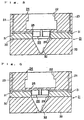
- Fig. 4 to Fig. 6 show a first embodiment of a fabrication machine of optical fiber according to the present invention.
- Fig.4 is a perspective view, seen from a lower side, of the fabrication machine, omitting a lower funnel-shaped spinning nozzle
- Fig.5 is a longitudinal cross section, taken along the line A - A shown in Fig.4, including the lower funnel-shaped spinning nozzle
- Fig.6 is a longitudinal cross section, taken along the line B - B shown in Fig.4, including the lower funnel-shaped spinning nozzle.
- the fabrication machine 21 of optical fiber comprises a ring-shaped spinning head 24 in its upper half, a spinning seat 33 in its lower half, and a circular-plate-shaped guide member 30 interposed therebetween.
- the ring-shaped spinning head 24 includes an island part polymer inlet 22 having a relatively large diameter in its center, a plurality of sea part polymer inlets 23 in its peripheral part, a bottom 25, and a concavo-convex-shaped partition wall 26 for a flow path control of the island part, mounted on the bottom 25, so as to surround the space corresponding to the island part.
- Flow paths 27 of the island part polymer are formed inside the partition wall 26, and flow paths (space or slits between adjacent projection wings) 28 for the sea part polymer outside the partition wall 26.
- the guide member 30 having an opening 29 to be matched to the external shape of the partition wall 26 in its central portion is fitted between the spinning head 24 and the spinning seat 33 in contact with the partition wall 26 so that a space may be formed between the bottom 25 of the spinning head 24 and the guide member 30 itself, this space constituting a guide path 31 for introducing the sea part polymer supplied from the sea part polymer inlets 23 into the slits 28 of the partition wall 26.
- the guide member 30 is mounted on the spinning seat 33 having a funnel-shaped spinning nozzle 32 matched to the opening 29 of the guide member 30.
- the island part polymer and the sea part polymer are supplied from the island part polymer inlet 22 and the sea part polymer inlets 23, respectively, the island part polymer is directly introduced into the flow paths 27 of the partition wall 26 to move down, and the sea part polymer passes from the lower ends of the sea part polymer inlets 23 through the guide path 31 to reach the slits 28 of the partition wall 26. Since there is no other flow passes for the sea part polymer, all the sea part polymer is introduced into the flow paths 28 of the partition wall 26 and flows down therein.
- a spinning is carried out using a fabrication machine of optical fiber, shown in Figs.4 to 6, and spinning extruders of composite fiber with a specification shown in Table 1 as a specific embodiment.
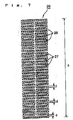
- An opening shape of a partition wall for a flow path control of an island part is shown in Fig.7.
- This partition wall is fitted in a rectangular opening having an internal size of 4.2 mm x 15.4 mm of the guide plate 30, thereby setting the partition wall.
- the island part polymer passing through the flow paths 27 within the partition wall 26 and the sea part polymer passing through the slits 28 surrounded by the partition wall 26 and the guide member 30 drop in the funnel-shaped spinning nozzle 32 while being spun by the spinning nozzle 32, discharging an optical fiber from a discharge hole.
- the size of the discharge hole is 4.3 mm x 0.1 mm.
- the obtained optical fiber has dimensions such as a thickness 0.08 ⁇ m of the wing, space or slit 0.12 ⁇ m between the adjacent wing, an entire fiber thickness (length) 50 ⁇ m in the direction of aligned wings, and an entire width 3.28 ⁇ m and exhibits the desired optical characteristics.
- Fig. 8 is a longitudinal cross section of a second embodiment of a fabrication machine of optical fiber according to the present invention. This embodiment is an improvement of the first embodiment described above.
- the same reference characters denote the same or corresponding parts as those in the first embodiment and thus the description thereof can be omitted for brevity.
- a circular guide member 30a having a central opening 29, to be fitted with the partition wall 26, is provided with a plurality of through-holes 34 having a relatively small diameter, which are arranged radially in somewhat outer position of the opening 29.
- the through-holes 34 connect the guide path 31 for the sea part polymer and the funnel-shaped spinning nozzle 32 so as to bypass a part of the sea part polymer supplied from the sea part polymer inlets 23 to the spinning nozzle 32 without passing through the flow paths or slits 28 of the partition wall 26, resulting in increasing the rate of the sea part polymer with respect to the island part polymer in the cross section of the spun optical fiber.
- an optical fiber having a small island part in its cross section can be obtained, as shown in Fig.1c, and a small-sized optical fiber can be prepared.
- Fig. 9 is a longitudinal cross section of a third embodiment of a fabrication machine of optical fiber according to the present invention. This embodiment is also an improvement of the first embodiment described above.
- the same reference characters denote the same or corresponding parts as those in the first embodiment and thus the description thereof can be omitted for brevity.
- a circular guide member 30b having a central opening 29, to be fitted with the partition wall 26, is provided with a step part 35 in the lower end portion of the opening 29 so as to project its inside.
- This step part 35 permits the guide member 30b to be exactly and easily fitted with the partition wall 26.
- the guide member 30b can be mounted on the partition wall 26 in a short time while carrying out an exact positioning of the same.
- Fig. 10 shows a fourth embodiment of a fabrication machine of optical fiber according to the present invention and is a perspective view, partly in section, seen from a lower side, of a partition wall for a flow path control of an island part.
- This embodiment is also an improvement of the first embodiment described above.
- the same reference characters denote the same or corresponding parts as those in the first embodiment and thus the description thereof can be omitted for brevity.
- the space in the machine is divided into the internal flow paths 27 for the island part polymer and the external slits 28 for the sea part polymer by the partition wall 26 for the flow path control of the island part.
- the space of the flow paths 27, positioned between a pair of opposite flow paths 28, are not connected in the longitudinal direction and are closed except lower step portions 36 between the pair of opposite flow paths 28.
- the pair of opposite slits 28 for the sea part polymer are connected so as to raise the strength of the partition wall 26.
- the sea part polymer can flow into the lower step portions 36 of the flow paths 27, and no negative influence can be given to the optical characteristics of the obtained optical fiber.
- a fabrication machine of optical fiber comprises a spinning head including a partition wall, mounted on a bottom, for a flow path control of an island part, having projection wings of flow paths for forming wings of an island part, an island part polymer inlet positioned within the partition wall for supplying an island part polymer, and sea part polymer inlets positioned in a peripheral part of the partition wall for supplying a sea part polymer; a spinning seat, mounted under the spinning head, having a funnel-shaped spinning nozzle for spinning the sea part polymer and the island part polymer into an optical fiber; and a guide member, mounted around the partition wall, for guiding the flow of the sea part polymer so as to introduce the sea part polymer supplied from the sea part polymer inlets to the funnel-shaped spinning nozzle through space between the adjacent projection wings of the partition wall.
- the sea part polymer supplied from the sea part polymer inlet is guided by the sea part polymer guide member so as to be exactly supplied into the slits between the projection wings of the partition wall, and the sea part polymer then joins together with the island part polymer passed through the inside of the partition wall 26. Accordingly, in the obtained optical fiber, the slits between the wings are sufficiently filled with the sea part polymer to prevent a mutual contact or fusion of the adjacent wings of the island part. As a result, the optical characteristics of the optical fiber are not damages and the optical fiber having the desired optical characteristics can be obtained.
- this guide member is tightly contacted to the partition wall.
- a small gap can be formed between the guide member and the partition wall as long as the flow resistance of the polymer passing through the gap is equal to, or smaller than, that passing through the slits of the partition wall 26.
- a sea part when an optical fiber having a large sea part or having a small island part is required, a sea part can be enlarged compared with an island part in its cross section of the obtained optical fiber.
- through-holes connecting the sea part polymer inlets to the funnel-shaped spinning nozzle are provided in the guide member.
- a plurality of through-holes having a small diameter are preferably provided in the guide member.
- a plurality of optical fibers are produced in one operation, and a plurality of fabrication machines of optical fiber are required to be installed in parallel.
- the fabrication machine of optical fiber is a very delicate apparatus suited to the size of the obtained optical fiber, and it is often troublesome to mount many guide member one by one around the respective partition wall in the fabrication machines.
- the guide member is made to be a plate having an opening to be matched to an external shape of the partition wall and having a step part to be fitted the partition wall with the step part of the guide member, the guide member can be readily fitted with the partition wall in a short time while positioning the guide member exactly.
Landscapes
- Engineering & Computer Science (AREA)
- Mechanical Engineering (AREA)
- Textile Engineering (AREA)
- Health & Medical Sciences (AREA)
- Manufacturing & Machinery (AREA)
- Ophthalmology & Optometry (AREA)
- Spinning Methods And Devices For Manufacturing Artificial Fibers (AREA)
Applications Claiming Priority (2)
| Application Number | Priority Date | Filing Date | Title |
|---|---|---|---|
| JP7278305A JPH0995817A (ja) | 1995-10-02 | 1995-10-02 | 光学繊維の製造装置 |
| JP278305/95 | 1995-10-02 |
Publications (2)
| Publication Number | Publication Date |
|---|---|
| EP0767259A2 true EP0767259A2 (de) | 1997-04-09 |
| EP0767259A3 EP0767259A3 (de) | 1997-06-11 |
Family
ID=17595498
Family Applications (1)
| Application Number | Title | Priority Date | Filing Date |
|---|---|---|---|
| EP96202733A Withdrawn EP0767259A3 (de) | 1995-10-02 | 1996-10-02 | Maschine für die Herstellung einer optischen Faser |
Country Status (4)
| Country | Link |
|---|---|
| US (1) | US5869107A (de) |
| EP (1) | EP0767259A3 (de) |
| JP (1) | JPH0995817A (de) |
| KR (1) | KR970022376A (de) |
Cited By (6)
| Publication number | Priority date | Publication date | Assignee | Title |
|---|---|---|---|---|
| EP0877102A1 (de) * | 1997-04-16 | 1998-11-11 | Nissan Motor Co., Ltd. | Verfahren zur Herstellung von Verbundfasern und Spinndüse dafür |
| WO2019152354A1 (en) * | 2018-01-31 | 2019-08-08 | Saudi Arabian Oil Company | Producing fibers using spinnerets |
| US11253819B2 (en) | 2020-05-14 | 2022-02-22 | Saudi Arabian Oil Company | Production of thin film composite hollow fiber membranes |
| US11331632B2 (en) | 2020-02-14 | 2022-05-17 | Saudi Arabian Oil Company | Thin film composite hollow fiber membranes fabrication systems |
| US11406941B2 (en) | 2020-02-14 | 2022-08-09 | Saudi Arabian Oil Company | Thin film composite hollow fiber membranes fabrication systems |
| US12116326B2 (en) | 2021-11-22 | 2024-10-15 | Saudi Arabian Oil Company | Conversion of hydrogen sulfide and carbon dioxide into hydrocarbons using non-thermal plasma and a catalyst |
Families Citing this family (11)
| Publication number | Priority date | Publication date | Assignee | Title |
|---|---|---|---|---|
| US20030190130A1 (en) * | 2002-04-05 | 2003-10-09 | Paradigm Optics, Inc. | Multiple optical pathway fiber optic cable |
| JP2005116593A (ja) * | 2003-10-03 | 2005-04-28 | Ube Ind Ltd | 熱電変換装置 |
| US7708688B2 (en) * | 2004-03-15 | 2010-05-04 | Paradigm Optics, Incorporated | Polymer endoscopic shaft |
| US9050036B2 (en) | 2007-06-19 | 2015-06-09 | Minimally Invasive Devices, Inc. | Device for maintaining visualization with surgical scopes |
| CN102307511B (zh) | 2008-12-10 | 2015-06-03 | 微创设备股份有限公司 | 使用手术窥镜期间优化和维持手术区可视化的系统 |
| USD613403S1 (en) | 2008-12-10 | 2010-04-06 | Minimally Invasive Devices, Llc | Sheath tip for maintaining surgical scope visualization |
| US9078562B2 (en) | 2010-01-11 | 2015-07-14 | Minimally Invasive Devices, Inc. | Systems and methods for optimizing and maintaining visualization of a surgical field during the use of surgical scopes |
| JP5968886B2 (ja) | 2010-08-04 | 2016-08-10 | ミニマリー インべーシブ デバイシーズ, インコーポレイテッド | 手術用顕微鏡を使用する間に術野の可視化を最適化および維持するためのシステムおよび方法 |
| WO2012075487A2 (en) | 2010-12-03 | 2012-06-07 | Minimally Invasive Devices, Llc | Devices, systems, and methods for performing endoscopic surgical procedures |
| US10398292B2 (en) | 2013-03-14 | 2019-09-03 | Floshield, Inc. | Fluid dispensing control systems and methods |
| CN107938003B (zh) * | 2017-11-10 | 2019-08-09 | 南通华盛高聚物科技股份有限公司 | 用于并列型复合纤维新材料工艺中的喷丝板以及喷丝工艺 |
Citations (7)
| Publication number | Priority date | Publication date | Assignee | Title |
|---|---|---|---|---|
| JPS59228042A (ja) | 1983-06-03 | 1984-12-21 | 株式会社クラレ | 鱗片構造繊維を含む織物 |
| JPS6024847B2 (ja) | 1980-04-07 | 1985-06-14 | 株式会社クラレ | 玉虫調効果を有するポリエステル繊維 |
| JPS62170510A (ja) | 1986-01-22 | 1987-07-27 | Toray Ind Inc | 干渉色を有する繊維 |
| JPS63120642A (ja) | 1986-11-10 | 1988-05-25 | 東レ株式会社 | 干渉色を有するシ−ト状物およびその製造方法 |
| JPS6364535B2 (de) | 1983-06-02 | 1988-12-12 | ||
| JPH01139803A (ja) | 1988-06-30 | 1989-06-01 | Toray Ind Inc | 異形断面繊維 |
| JPH0617349A (ja) | 1992-06-30 | 1994-01-25 | Nissan Motor Co Ltd | 自然光の反射、干渉作用を有する構造体 |
Family Cites Families (16)
| Publication number | Priority date | Publication date | Assignee | Title |
|---|---|---|---|---|
| US3531368A (en) * | 1966-01-07 | 1970-09-29 | Toray Industries | Synthetic filaments and the like |
| US3716614A (en) * | 1969-05-12 | 1973-02-13 | Toray Industries | Process of manufacturing collagen fiber-like synthetic superfine filament bundles |
| GB1302584A (de) * | 1970-06-23 | 1973-01-10 | ||
| GB1346103A (en) * | 1971-06-18 | 1974-02-06 | Ici Ltd | Apparatus for the manufacture of eccentric core/sheath cojugate filaments |
| EP0011954B1 (de) * | 1978-11-30 | 1982-12-08 | Imperial Chemical Industries Plc | Vorrichtung zum Spinnen von Bikomponentenfilamenten |
| JPS57143507A (en) * | 1981-02-18 | 1982-09-04 | Toray Ind Inc | Spinneret device for conjugate fiber |
| JPS60162804A (ja) * | 1984-02-02 | 1985-08-24 | Toray Ind Inc | 海島型複合繊維の紡糸方法 |
| JPS61184874A (ja) * | 1985-02-12 | 1986-08-18 | Matsushita Electronics Corp | 半導体装置 |
| JPS623038A (ja) * | 1985-06-28 | 1987-01-09 | Mitsubishi Rayon Co Ltd | 光伝送性集合フアイバ−製造用紡糸口金装置 |
| JPS62228042A (ja) * | 1985-07-23 | 1987-10-06 | Ajinomoto Co Inc | 液晶 |
| JPH01291206A (ja) * | 1988-05-19 | 1989-11-22 | Fujitsu Ltd | 光半導体モジュール |
| JPH035532A (ja) * | 1989-06-01 | 1991-01-11 | Fuji Electric Co Ltd | 地下水利用システムの沈澱池 |
| JPH07226787A (ja) * | 1994-02-14 | 1995-08-22 | Nippondenso Co Ltd | 電話機 |
| JPH08226012A (ja) * | 1995-02-16 | 1996-09-03 | Tanaka Kikinzoku Kogyo Kk | 光学機能異形断面繊維製造用紡糸口金 |
| JPH08226011A (ja) * | 1995-02-16 | 1996-09-03 | Tanaka Kikinzoku Kogyo Kk | 光学機能異形断面繊維製造用紡糸口金 |
| JPH08218218A (ja) * | 1995-02-16 | 1996-08-27 | Tanaka Kikinzoku Kogyo Kk | 光学機能繊維の製造方法 |
-
1995
- 1995-10-02 JP JP7278305A patent/JPH0995817A/ja active Pending
-
1996
- 1996-10-02 US US08/724,747 patent/US5869107A/en not_active Expired - Fee Related
- 1996-10-02 EP EP96202733A patent/EP0767259A3/de not_active Withdrawn
- 1996-10-02 KR KR1019960043591A patent/KR970022376A/ko not_active Abandoned
Patent Citations (7)
| Publication number | Priority date | Publication date | Assignee | Title |
|---|---|---|---|---|
| JPS6024847B2 (ja) | 1980-04-07 | 1985-06-14 | 株式会社クラレ | 玉虫調効果を有するポリエステル繊維 |
| JPS6364535B2 (de) | 1983-06-02 | 1988-12-12 | ||
| JPS59228042A (ja) | 1983-06-03 | 1984-12-21 | 株式会社クラレ | 鱗片構造繊維を含む織物 |
| JPS62170510A (ja) | 1986-01-22 | 1987-07-27 | Toray Ind Inc | 干渉色を有する繊維 |
| JPS63120642A (ja) | 1986-11-10 | 1988-05-25 | 東レ株式会社 | 干渉色を有するシ−ト状物およびその製造方法 |
| JPH01139803A (ja) | 1988-06-30 | 1989-06-01 | Toray Ind Inc | 異形断面繊維 |
| JPH0617349A (ja) | 1992-06-30 | 1994-01-25 | Nissan Motor Co Ltd | 自然光の反射、干渉作用を有する構造体 |
Non-Patent Citations (2)
| Title |
|---|
| PROC. OF THE TEXTILE MACHINERY SOC. OF JAPAN., vol. 42, no. 10, 1989, pages 60 |
| PROC. OF THE TEXTILE MACHINERY SOC. OF JAPAN., vol. 42, no. 2, 1989, pages 55 |
Cited By (8)
| Publication number | Priority date | Publication date | Assignee | Title |
|---|---|---|---|---|
| EP0877102A1 (de) * | 1997-04-16 | 1998-11-11 | Nissan Motor Co., Ltd. | Verfahren zur Herstellung von Verbundfasern und Spinndüse dafür |
| WO2019152354A1 (en) * | 2018-01-31 | 2019-08-08 | Saudi Arabian Oil Company | Producing fibers using spinnerets |
| US10889915B2 (en) | 2018-01-31 | 2021-01-12 | Saudi Arabian Oil Company | Producing fibers using spinnerets |
| US11674241B2 (en) | 2018-01-31 | 2023-06-13 | Saudi Arabian Oil Company | Producing fibers using spinnerets |
| US11331632B2 (en) | 2020-02-14 | 2022-05-17 | Saudi Arabian Oil Company | Thin film composite hollow fiber membranes fabrication systems |
| US11406941B2 (en) | 2020-02-14 | 2022-08-09 | Saudi Arabian Oil Company | Thin film composite hollow fiber membranes fabrication systems |
| US11253819B2 (en) | 2020-05-14 | 2022-02-22 | Saudi Arabian Oil Company | Production of thin film composite hollow fiber membranes |
| US12116326B2 (en) | 2021-11-22 | 2024-10-15 | Saudi Arabian Oil Company | Conversion of hydrogen sulfide and carbon dioxide into hydrocarbons using non-thermal plasma and a catalyst |
Also Published As
| Publication number | Publication date |
|---|---|
| KR970022376A (ko) | 1997-05-28 |
| EP0767259A3 (de) | 1997-06-11 |
| JPH0995817A (ja) | 1997-04-08 |
| US5869107A (en) | 1999-02-09 |
Similar Documents
| Publication | Publication Date | Title |
|---|---|---|
| US5869107A (en) | Fabrication machine of optical fiber | |
| US5516476A (en) | Process for making a fiber containing an additive | |
| JP3483379B2 (ja) | 発色構造体 | |
| US4812012A (en) | Optical fiber array having fiber islands in a polymer sea | |
| US5407738A (en) | Minute structure for showing colors by reflection and interference of natural light | |
| CA2055770A1 (en) | Interfacial surface generator | |
| US5753277A (en) | Spinneret for manufacturing modified cross-section fibers with optical function | |
| DE19604445A1 (de) | Farbdarstellungsstruktur | |
| US4732716A (en) | Process for preparation of multifilament optical fibers | |
| EP0767260A2 (de) | Optische Faser und Verfahren und Vorrichtung zu ihrer Herstellung | |
| JPH04126214A (ja) | 金型 | |
| KR20100088431A (ko) | 휘도강화필름 | |
| US5731010A (en) | Spinneret for manufacturing modified cross-section fibers with optical function | |
| KR100951700B1 (ko) | 광변조 물체의 제조방법 | |
| CN114080318A (zh) | 用于使用3d打印功能晶片制作光学镜片的具有热/冷循环的注射包覆模制 | |
| GB2297942A (en) | Method of manufacturing fibers with improved visual properties | |
| JP2007039858A (ja) | 規則性極微構造繊維の形成方法 | |
| EP0877102B1 (de) | Verfahren zur Herstellung von Verbundfasern und Spinndüse dafür | |
| CN111850719B (zh) | 反光纤维及其喷丝组件 | |
| US20250144867A1 (en) | Cluster of Polymeric Columns and Method of Making Same | |
| KR20210042053A (ko) | 비정형 컬러 믹싱 사출 성형 시스템 | |
| JP3358651B2 (ja) | 複合高分子繊維紡糸用口金 | |
| KR101094130B1 (ko) | 액정표시장치 | |
| JP3135313B2 (ja) | 熱可塑性樹脂シートの製造方法及びその装置 | |
| KR101109134B1 (ko) | 광변조필름의 제조방법 |
Legal Events
| Date | Code | Title | Description |
|---|---|---|---|
| PUAI | Public reference made under article 153(3) epc to a published international application that has entered the european phase |
Free format text: ORIGINAL CODE: 0009012 |
|
| AK | Designated contracting states |
Kind code of ref document: A2 Designated state(s): DE FR GB |
|
| PUAL | Search report despatched |
Free format text: ORIGINAL CODE: 0009013 |
|
| AK | Designated contracting states |
Kind code of ref document: A3 Designated state(s): DE FR GB |
|
| 17P | Request for examination filed |
Effective date: 19971202 |
|
| 17Q | First examination report despatched |
Effective date: 19991111 |
|
| RTI1 | Title (correction) |
Free format text: FABRICATION MACHINE FOR MAKING FIBERS HAVING OPTICAL PROPERTIES |
|
| STAA | Information on the status of an ep patent application or granted ep patent |
Free format text: STATUS: THE APPLICATION HAS BEEN WITHDRAWN |
|
| 18W | Application withdrawn |
Withdrawal date: 20000927 |