EP0767330A2 - Electrovanne de manifold - Google Patents
Electrovanne de manifold Download PDFInfo
- Publication number
- EP0767330A2 EP0767330A2 EP96306176A EP96306176A EP0767330A2 EP 0767330 A2 EP0767330 A2 EP 0767330A2 EP 96306176 A EP96306176 A EP 96306176A EP 96306176 A EP96306176 A EP 96306176A EP 0767330 A2 EP0767330 A2 EP 0767330A2
- Authority
- EP
- European Patent Office
- Prior art keywords
- output
- manifold
- openings
- change
- legs
- Prior art date
- Legal status (The legal status is an assumption and is not a legal conclusion. Google has not performed a legal analysis and makes no representation as to the accuracy of the status listed.)
- Granted
Links
- 239000012530 fluid Substances 0.000 description 13
- 238000007789 sealing Methods 0.000 description 3
- 230000004075 alteration Effects 0.000 description 2
- 238000004519 manufacturing process Methods 0.000 description 2
- 230000000994 depressogenic effect Effects 0.000 description 1
- 239000002184 metal Substances 0.000 description 1
Images

Classifications
-
- F—MECHANICAL ENGINEERING; LIGHTING; HEATING; WEAPONS; BLASTING
- F15—FLUID-PRESSURE ACTUATORS; HYDRAULICS OR PNEUMATICS IN GENERAL
- F15B—SYSTEMS ACTING BY MEANS OF FLUIDS IN GENERAL; FLUID-PRESSURE ACTUATORS, e.g. SERVOMOTORS; DETAILS OF FLUID-PRESSURE SYSTEMS, NOT OTHERWISE PROVIDED FOR
- F15B13/00—Details of servomotor systems ; Valves for servomotor systems
- F15B13/02—Fluid distribution or supply devices characterised by their adaptation to the control of servomotors
- F15B13/06—Fluid distribution or supply devices characterised by their adaptation to the control of servomotors for use with two or more servomotors
- F15B13/08—Assemblies of units, each for the control of a single servomotor only
- F15B13/0803—Modular units
- F15B13/0821—Attachment or sealing of modular units to each other
- F15B13/0825—Attachment or sealing of modular units to each other the modular elements being mounted on a common member, e.g. on a rail
-
- F—MECHANICAL ENGINEERING; LIGHTING; HEATING; WEAPONS; BLASTING
- F15—FLUID-PRESSURE ACTUATORS; HYDRAULICS OR PNEUMATICS IN GENERAL
- F15B—SYSTEMS ACTING BY MEANS OF FLUIDS IN GENERAL; FLUID-PRESSURE ACTUATORS, e.g. SERVOMOTORS; DETAILS OF FLUID-PRESSURE SYSTEMS, NOT OTHERWISE PROVIDED FOR
- F15B13/00—Details of servomotor systems ; Valves for servomotor systems
- F15B13/02—Fluid distribution or supply devices characterised by their adaptation to the control of servomotors
- F15B13/06—Fluid distribution or supply devices characterised by their adaptation to the control of servomotors for use with two or more servomotors
- F15B13/08—Assemblies of units, each for the control of a single servomotor only
- F15B13/0803—Modular units
- F15B13/0807—Manifolds
- F15B13/0817—Multiblock manifolds
-
- F—MECHANICAL ENGINEERING; LIGHTING; HEATING; WEAPONS; BLASTING
- F15—FLUID-PRESSURE ACTUATORS; HYDRAULICS OR PNEUMATICS IN GENERAL
- F15B—SYSTEMS ACTING BY MEANS OF FLUIDS IN GENERAL; FLUID-PRESSURE ACTUATORS, e.g. SERVOMOTORS; DETAILS OF FLUID-PRESSURE SYSTEMS, NOT OTHERWISE PROVIDED FOR
- F15B13/00—Details of servomotor systems ; Valves for servomotor systems
- F15B13/02—Fluid distribution or supply devices characterised by their adaptation to the control of servomotors
- F15B13/06—Fluid distribution or supply devices characterised by their adaptation to the control of servomotors for use with two or more servomotors
- F15B13/08—Assemblies of units, each for the control of a single servomotor only
- F15B13/0803—Modular units
- F15B13/0832—Modular valves
- F15B13/0839—Stacked plate type valves
-
- F—MECHANICAL ENGINEERING; LIGHTING; HEATING; WEAPONS; BLASTING
- F15—FLUID-PRESSURE ACTUATORS; HYDRAULICS OR PNEUMATICS IN GENERAL
- F15B—SYSTEMS ACTING BY MEANS OF FLUIDS IN GENERAL; FLUID-PRESSURE ACTUATORS, e.g. SERVOMOTORS; DETAILS OF FLUID-PRESSURE SYSTEMS, NOT OTHERWISE PROVIDED FOR
- F15B13/00—Details of servomotor systems ; Valves for servomotor systems
- F15B13/02—Fluid distribution or supply devices characterised by their adaptation to the control of servomotors
- F15B13/06—Fluid distribution or supply devices characterised by their adaptation to the control of servomotors for use with two or more servomotors
- F15B13/08—Assemblies of units, each for the control of a single servomotor only
- F15B13/0803—Modular units
- F15B13/0846—Electrical details
- F15B13/0857—Electrical connecting means, e.g. plugs, sockets
-
- F—MECHANICAL ENGINEERING; LIGHTING; HEATING; WEAPONS; BLASTING
- F16—ENGINEERING ELEMENTS AND UNITS; GENERAL MEASURES FOR PRODUCING AND MAINTAINING EFFECTIVE FUNCTIONING OF MACHINES OR INSTALLATIONS; THERMAL INSULATION IN GENERAL
- F16K—VALVES; TAPS; COCKS; ACTUATING-FLOATS; DEVICES FOR VENTING OR AERATING
- F16K27/00—Construction of housing; Use of materials therefor
- F16K27/003—Housing formed from a plurality of the same valve elements
-
- Y—GENERAL TAGGING OF NEW TECHNOLOGICAL DEVELOPMENTS; GENERAL TAGGING OF CROSS-SECTIONAL TECHNOLOGIES SPANNING OVER SEVERAL SECTIONS OF THE IPC; TECHNICAL SUBJECTS COVERED BY FORMER USPC CROSS-REFERENCE ART COLLECTIONS [XRACs] AND DIGESTS
- Y10—TECHNICAL SUBJECTS COVERED BY FORMER USPC
- Y10T—TECHNICAL SUBJECTS COVERED BY FORMER US CLASSIFICATION
- Y10T137/00—Fluid handling
- Y10T137/5109—Convertible
- Y10T137/5283—Units interchangeable between alternate locations
-
- Y—GENERAL TAGGING OF NEW TECHNOLOGICAL DEVELOPMENTS; GENERAL TAGGING OF CROSS-SECTIONAL TECHNOLOGIES SPANNING OVER SEVERAL SECTIONS OF THE IPC; TECHNICAL SUBJECTS COVERED BY FORMER USPC CROSS-REFERENCE ART COLLECTIONS [XRACs] AND DIGESTS
- Y10—TECHNICAL SUBJECTS COVERED BY FORMER USPC
- Y10T—TECHNICAL SUBJECTS COVERED BY FORMER US CLASSIFICATION
- Y10T137/00—Fluid handling
- Y10T137/8593—Systems
- Y10T137/877—With flow control means for branched passages
- Y10T137/87885—Sectional block structure
Definitions
- This invention relates to a manifold-type solenoid valve comprising a series of change-over valves disposed on a manifold.
- Japanese Provisional Patent Publication No. 109157 of 1994 discloses a manifold-type solenoid change-over valve having five ports. Two each output ports are provided in the top of valve body and in the front of the manifold. The two each output ports are selectively used depending on the disposition and other conditions of the hydraulically operated unit to be controlled by the solenoid change-over valve, thereby permitting selection of the direction in which piping from the output ports are oriented.
- This change-over valve is effective in permitting selective use of the two each output ports disposed in two different planes. Practically, however, pipe connection to the necessary output port, closing of unnecessary output ports, and alteration of pipe connection must be done individually. This necessitates much labor, especially when many change-over valves are used together. Therefore, ways to facilitate pipe connection, closing and alteration in the selective use of the two each differently disposed output ports have been desired.
- An object of this invention is to provide means for facilitating connection of pipe to and closing of the output ports in a manifold-type solenoid valve having two each differently oriented output ports that can be individually opened and closed to permit outputting hydraulic fluid in the desired direction.
- Another object of this invention is to provide means for permitting such pipe connection and port closing using common parts, thereby reducing the number of parts required for piping and closing and reducing manufacturing costs to a minimum.
- a manifold-type solenoid valve essentially comprises a manifold on the top of which are disposed a required number of change-over valves.
- Common supply and discharge ducts provided in the manifold to communicate with the supply and discharge ports of each change-over valve open in the top surface of the manifold.
- More than one pair of first output openings individually communicating with a pair of first output ports of each change-over valve through said openings in the top surface are provided in the front surface of the manifold.
- Each change-over valve has a pair of first output ports and a pair of second output ports communicating therewith in the valve body thereof. The second output ports open in the top of the change-over valve. The action of the solenoid in the valve body switches the connection of the output ports between the supply and discharge ports.
- Engaging openings are provided on both sides of the first output openings so that the legs of a substantially U-shaped stopper pin inserted into the corresponding legs of the fit-in groove project into the first output openings.
- Engaging grooves to catch the legs of the stopper pin inserted into the legs of the fit-in groove and protruding into the first output openings through the engaging openings are provided around the periphery of pipe fittings and opening closing plugs to be fitted in the first output openings.
- a pair of the second output openings in the change-over valve are of the same diameter as that of the first output openings.
- a fit-in groove with similarly spaced legs to insert a U-shaped stopper pin are provided on both sides of the second output openings.
- Engaging openings are provided to allow the legs of the stopper pin to project into the second output openings.
- Pipe fittings or closing plugs are secured in all of the first and second output openings by means of common stopper pins that engage with the engaging grooves provided on the pipe fittings and closing plugs.
- the single manifold of the manifold-type solenoid valve according to this invention is formed by assembling a required number of manifold blocks each having a solenoid operated change-over valve mounted on top thereof.
- Pipe fittings and closing plugs are selectively fitted to the paired first and second output openings of the manifold-type solenoid valve.
- the pipe fittings and closing plugs are fastened to the output openings by means of the legs of a stopper pin that engage with the engaging grooves on the pipe fittings and closing plugs when inserted into the legs of the fit-in groove.
- the same stopper pins are used with both first and second output openings and both of pipe fittings and closing plugs.
- Pipe fittings and closing plugs can be easily fitted, removed or changed by inserting the legs of the stopper pins into the legs of the fit-in groove and pulling them out therefrom.
- Relatively free space available in front of the manifold block and on top of the change-over valve permits easy fitting, removal and changing of pipe fittings and closing plugs.
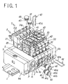
- Fig. 1 is a perspective view of a manifold-type solenoid valve embodying the principle of this invention.
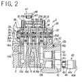
- Fig. 2 is a vertical cross-sectional view showing the principal parts of the same embodiment.
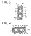
- Fig. 3 is a cross-sectional view illustrating how a pipe fittings and closing plugs are fitted to the first output openings of the same embodiment.
- Fig. 4 is a cross-sectional view illustrating how a pipe fittings and closing plugs are fitted to the second output openings of the same embodiment.
- Fig. 5 shows schematic illustrations of typical applications of the manifold-type solenoid valve according to this invention at A through F.
- Fig. 1 shows a preferred embodiment of this invention.
- This manifold-type solenoid valve comprises a required number of units (five units are assembled in the illustrated example), each unit comprising a manifold block 2 and a solenoid operated change-over valve 3 mounted on the manifold block 2 by means of fastening bolts 4, assembled along a rail 1.
- An end block 6a is fitted to one end of the assembled manifold blocks 2, with a supply and discharge block 5 disposed therebetween, whereas an end block 6b is directly fitted to the other end.
- the end blocks 6a and 6b are fastened to the rail 1 by means of fastening bolts 7 (Fig. 1 shows only one of the fastening bolts).
- the illustrated manifold is formed by assembling a required number of manifold blocks 2, a supply and discharge block 5 at one end, and end blocks 6a and 6b at both ends that are mounted on the rail 1. All member units may be fabricated in one piece, or manifold blocks 2 may be fabricated as one manifold.
- the manifold block 2 has a supply duct 11 to convey compressed air or other hydraulic fluid, a pair of discharge ducts 12a and 12b, and a pair of pilot discharge ducts 13a and 13b, all extending in the direction in which manifold blocks are joined together.
- the ducts in each manifold block 2 communicate with the ducts in other manifold blocks 2 that are assembled, with the leakage of the hydraulic fluid conveyed therethrough prevented by means of seals, not shown, provided between the individual blocks.
- the supply duct 11, discharge ducts 12a and 12b, pilot discharge ducts 13a and 13b are closed by end blocks 6a and 6b at both ends of the assembled blocks.
- the supply duct 11 communicates with a supply opening P in the front surface of the supply and discharge block 5, whereas the discharge ducts 12a and 12b and the pilot discharge ducts 13a and 13b communicate with a discharge opening R in the same front surface of the supply and discharge block 5.
- the supply duct 11 connects to an opening 14 in the middle of the top surface thereof on which the change-over valve 3 is mounted. Openings 15a and 15b on both sides of the opening 14 connect to first output openings A 1 and B 1 that are provided, one on top of the other, in the front surface of the manifold block 2. Openings 16a and 16b on both sides of the openings 15a and 15b connect to the discharge ducts 12a and 12b, whereas openings 17a and 17b on both sides of the openings 16a and 16b connect to the pilot discharge ducts 13a and 13b.
- the change-over valve 3 is a pilot-type change-over valve comprising a main valve 20 and a pilot valve 21 which is a solenoid-actuated three-port valve.
- the change-over valve 3 is mounted on the manifold block 2.
- the valve casing 23 of the main valve 20 has a valve bore 24 extending in the direction in which the openings in the top surface of the manifold block 2 where the change-over valve is mounted are provided.
- a supply port 25 opening in the bottom surface of the valve casing 23 and communicating with the opening 14, first output ports 26A and 26B communicating with the openings 15a and 15b, and discharge ports 28a and 28b communicating with the openings 16a and 16b connect to the valve bore 24.
- Second output ports 27A and 27B individually communicating with second output openings A 2 and B 2 in a port block 30 fastened to the top surface of the valve casing 23 by means of fastening bolts 31 are provided above and opposite the first output ports 26A and 26B in the valve bore 24.
- That end of a valve body 33 slidably fitted in the valve bore 24 which is closer to the pilot valve 21 is in contact with a piston 34 having a sufficiently larger diameter.
- the piston 34 moves to cause the valve body 33 to slide to the right in Fig. 2, thereby connecting the supply port 25 to the output ports 26A and 27A and the output ports 26B and 27B to the discharge port 28b.
- the pilot fluid is discharged from the pilot chamber 35, the fluid pressure constantly acting on the pressure chamber opposite the pilot valve through a supply passage 36 communicating with the supply port 25 causes the valve body 33 to slide to the left in Fig. 2, thereby connecting t he supply port 25 to the output ports 26B and 27B and the output ports 26A and 27A to the discharge port 28a.
- the pilot valve 21 is a three-port solenoid valve of known type having a pilot supply port connecting to the supply passage 36, a pilot output port connecting to the pilot chamber 35 behind the piston 34, and a pilot discharge port connecting to a pilot discharge passage 29 in the valve casing 23. Energization and de-energization of the a solenoid 21a switches the connection of the pilot output port from the pilot supply port to the pilot discharge port and vice versa.
- the pilot discharge passage 29 in the valve casing 23 of the change-over valve 3 is provided to communicate with the opening 17a of the pilot discharge duct 13a in the manifold block 2.
- the opening 17b of the other pilot discharge duct 13b in the manifold block 2, which is closed in the illustration, is used when two pilot valves 21 are attached to both ends of the valve casing 23.
- the first output openings A 1 and B 1 in the manifold block 2 and the second output openings A 2 and B 2 in the port block 30 are all of the same diameter. Therefore, the same pipe fittings 40, closing plugs 41 and stopper pins 42 can be used with the first output openings A 1 and B 1 and the second output openings A 2 and B 2 .
- the pipe fitting 40 is a pipe fitting of known one-touch type that automatically achieves engagement of a piping tube when the tube is inserted in the connection port 40a thereof. The engagement of the piping tube is released when a release bushing 40b is depressed.
- a seal ring 45 to seal the gap between the outer surface of the cylindrical part 40c inserted and the output openings and an engaging groove 46 to catch the stopper pin 42 are provided around the periphery of the cylindrical part 40c.
- the plugs 41 which have the same diameter as the pipe fittings 40, is used for closing unused output openings.
- the plugs 41 have a seal ring 47 and an engaging groove 48 therearound like the pipe fittings 40.
- an inverted U-shaped fit-in groove 51 extending downward on both sides of the manifold block 2 from the top surface thereof is provided so that the legs thereof run down on both sides of the first output openings A 1 and B 1 in the manifold block 2.
- the fit-in groove 51 accommodates a substantially U-shaped stopper pin 42 of elastic metal wire. The distance between the legs of the fit-in groove 51 is smaller than the diameter of the first output openings A 1 and B 1 .
- An engaging opening 52 through which the legs 42a of the stopper pin 42 inserted in the fit-in groove 51 project into the first output openings A 1 and B 1 is provided on each side of the first output openings A 1 and B 1 .
- the pipe fitting 40 or the closing plug 41 is fitted in the first output opening A 1 and B 1 by placing the engaging groove 46 or 48 provided on the pipe fitting 40 or the closing plug 41 in the engaging opening 52 and bringing the legs 42a of the stopper pin 42 inserted in the fit-in groove 51 into engagement with the engaging groove 46 or 48 on the pipe fitting 40 or the closing plug 41, with the sealing ring 45 or 47 sealing the gap between the pipe fitting 40 or the closing plug 41 and the output openings A 1 and B 1 .
- the port block 30 has a fit-in groove 53 to accommodate the stopper pin 42, with the legs thereof extending on both sides of the second output openings A 2 and B 2 (see Figs. 1 and 4). As in the case of the first output openings A1 and B1, the distance between the legs of the fit-in groove 53 is smaller than the diameter of the second output openings A 2 and B 2 .
- the same pipe fitting 40, closing plug 41 and stopper pin 42 as those used with the first output openings A 1 and B 1 are used with the second output openings A 2 and B 2 , with the same seal rings 45 and 47 used for sealing.
- the pipe fittings 40 and closing plugs 41 are fastened in the first output openings A 1 and B 1 and the second output openings A 2 and B 2 by fitting the pipe fittings or closing plugs as required and inserting the stopper pins 42 in the fit-in grooves 51 and 53. Because the pipe fittings 40 and closing plugs 41 can be selectively fitted to the output openings as required using the same stopper pins 42, the change-over valve can be used in various combinations, as will be discussed by reference to the schematic illustrations in Fig. 5.
- Fig. 5-D the pipe fittings 40 are fitted in the first output opening B 1 and the second output opening A 2 and the closing plugs 41 in the first output opening A 1 and the second output opening B 2 .
- the hydraulic fluid is outputted from the first output opening B 1 in the front of the manifold block and the second output opening A 2 in the top of the change-over valve.
- the hydraulic fluid can be outputted from any desired output openings by fitting the pipe fittings 40 or closing plugs 41 in the desired output openings.
- the change-over valve 3 becomes a normally open three-port valve when the closing plugs 41 are fitted in the first output openings A 1 and B 1 and the second output opening A 2 and the pipe fitting 40 in the second output opening B 2 as shown in Fig. 5-E.
- the change-over valve 3 becomes a normally closed three-port valve when the closing plugs 41 are fitted in the first output openings A 1 and B 1 and the second output opening B 2 and the pipe fitting 40 in the second output opening A 2 as shown in Fig. 5-F.
- the same result is obtained when the pipe fitting 40 is fitted in the first output opening B 1 or the first output opening A 2 alone.
- the pipe fittings 40 and closing plugs 41 can both be fitted in and detached from the first output openings A 1 and B 1 and the second output opening A 2 and B 2 by inserting the same stopper pins 42 into the fit-in grooves 51 and 52 and withdrawing the stopper pins therefrom.
- the pipe fittings 40 and closing plugs are easy to replace and change. Furthermore, replacement and changing can be accomplished with ease in the relatively free space in front of the manifold block or above the change-over valve.
- a required number of change-over valves can be assembled on the rail 1 with one or more combinations of the pipe fittings 40 and closing plugs 41.
- the same change-over valves 3 can be converted into various combinations of five-port change-over valves, normally open and closed three-port valves, as desired.
- this invention is by no means limited to the five-port changer-over valve having the main valve 20 and the solenoid operated pilot valve 21, but is also applicable to direct-acting change-over valves whose valve body is directly actuated by the energization and de-energization of the solenoid.
- the manifold-type solenoid valve according to this invention has two each differently oriented output ports that can be individually opened and closed to permit outputting the hydraulic fluid in the desired direction.
- the manifold-type solenoid valve of this invention facilitates the pipe connection to and closing of the output ports, using common parts. This permits reducing the number of parts required for piping and closing, thereby reducing manufacturing costs to a minimum.
Landscapes
- Engineering & Computer Science (AREA)
- General Engineering & Computer Science (AREA)
- Mechanical Engineering (AREA)
- Physics & Mathematics (AREA)
- Fluid Mechanics (AREA)
- Valve Housings (AREA)
- Magnetically Actuated Valves (AREA)
- Quick-Acting Or Multi-Walled Pipe Joints (AREA)
Applications Claiming Priority (3)
| Application Number | Priority Date | Filing Date | Title |
|---|---|---|---|
| JP278439/95 | 1995-10-02 | ||
| JP27843995 | 1995-10-02 | ||
| JP27843995A JP3644732B2 (ja) | 1995-10-02 | 1995-10-02 | マニホールド形電磁弁 |
Publications (3)
| Publication Number | Publication Date |
|---|---|
| EP0767330A2 true EP0767330A2 (fr) | 1997-04-09 |
| EP0767330A3 EP0767330A3 (fr) | 1997-05-07 |
| EP0767330B1 EP0767330B1 (fr) | 2001-11-21 |
Family
ID=17597362
Family Applications (1)
| Application Number | Title | Priority Date | Filing Date |
|---|---|---|---|
| EP19960306176 Expired - Lifetime EP0767330B1 (fr) | 1995-10-02 | 1996-08-23 | Electrovanne de manifold |
Country Status (6)
| Country | Link |
|---|---|
| US (1) | US5699834A (fr) |
| EP (1) | EP0767330B1 (fr) |
| JP (1) | JP3644732B2 (fr) |
| KR (1) | KR970021869A (fr) |
| CN (1) | CN1095961C (fr) |
| DE (1) | DE69617158T2 (fr) |
Cited By (8)
| Publication number | Priority date | Publication date | Assignee | Title |
|---|---|---|---|---|
| WO2000052370A1 (fr) * | 1999-03-01 | 2000-09-08 | Abb Offshore Systems, Inc. | Ensemble de soupapes pour reguler un flux de fluide hydraulique vers un système sous-marin |
| WO2002029202A1 (fr) * | 2000-10-06 | 2002-04-11 | Abb Offshore Systems Limited | Commande de puits d'hydrocarbures |
| EP1172590A3 (fr) * | 2000-07-12 | 2002-04-17 | Georg Schünemann GmbH | Soupapes pour gaz montées par blocks sur un support |
| EP1239242A1 (fr) * | 1999-06-25 | 2002-09-11 | York Neige | Fixation d'accessoires sur le corps d'une vanne du type vanne d'alimentation d'un canon a neige |
| WO2007140851A1 (fr) * | 2006-06-07 | 2007-12-13 | Festo Ag & Co. Kg | Agencement de soupape |
| EP1930637A3 (fr) * | 2006-12-08 | 2009-08-19 | Festo AG & Co. KG | Dispositif de raccordement pour vannes et bloc vanne équipé de celui-ci |
| WO2013114124A1 (fr) * | 2012-02-03 | 2013-08-08 | Parker Hannifin Manufacturing Limited | Système modulaire de régulation de fluide |
| US20200326024A1 (en) * | 2019-04-10 | 2020-10-15 | Robert Bosch Gmbh | Range of Rapid Couplers with Different Coupler Cartridges |
Families Citing this family (52)
| Publication number | Priority date | Publication date | Assignee | Title |
|---|---|---|---|---|
| TW371026U (en) * | 1996-05-23 | 1999-09-21 | Smc Corp | Solenoid valve with switch |
| USD415824S (en) * | 1996-05-28 | 1999-10-26 | Smc Corporation | Electromagnetic valve |
| USD415558S (en) | 1996-05-28 | 1999-10-19 | Smc Corporation | Electromagnetic valve |
| US5860450A (en) * | 1997-07-17 | 1999-01-19 | Hadley Products Corporation | Height control valve for vehicle leveling system |
| GB9715511D0 (en) * | 1997-07-24 | 1997-10-01 | Emhart Glass Mach Invest | Valve block |
| JP4045366B2 (ja) * | 1997-08-11 | 2008-02-13 | Smc株式会社 | 流体圧機器用配管継手 |
| US6102068A (en) * | 1997-09-23 | 2000-08-15 | Hewlett-Packard Company | Selector valve assembly |
| US6076543A (en) * | 1997-11-06 | 2000-06-20 | United States Filter Corporation | Gas handling device |
| US6189807B1 (en) | 1998-03-31 | 2001-02-20 | Spraying Systems Co. | Valve controlled spraying system |
| US6036107A (en) * | 1998-03-31 | 2000-03-14 | Spraying System Co. | Control valve arrangement for spraying systems |
| USD416980S (en) * | 1998-04-13 | 1999-11-23 | Smc Corporation | Supply and exhaust block for manifold solenoid valve |
| USD415559S (en) | 1998-04-13 | 1999-10-19 | Smc Corporation | Solenoid operated pilot valve |
| USD413650S (en) | 1998-04-13 | 1999-09-07 | Smc Corporation | Solenoid-operated pilot valve |
| USD417485S (en) | 1998-04-13 | 1999-12-07 | Smc Corporation | Solenoid-operated pilot valve |
| JPH11325291A (ja) * | 1998-05-14 | 1999-11-26 | Smc Corp | 切換弁用マニホールド |
| USD432987S (en) * | 1999-10-01 | 2000-10-31 | Smc Kabushiki Kaisha | Signal converter |
| USD443586S1 (en) | 1999-10-18 | 2001-06-12 | Smc Kabushiki Kaisha | Signal input/output converter |
| USD443248S1 (en) | 1999-10-18 | 2001-06-05 | Smc Kabushiki Kaisha | Signal-input device |
| USD443587S1 (en) | 1999-10-18 | 2001-06-12 | Smc Kabushiki Kaisha | Signal input device |
| JP3863769B2 (ja) * | 2001-12-04 | 2006-12-27 | Smc株式会社 | 電磁弁用マニホールド |
| US7073825B2 (en) * | 2002-04-10 | 2006-07-11 | Smc Corporation | One-operation piping-installation fluid pressure apparatus |
| JP3843060B2 (ja) * | 2002-11-07 | 2006-11-08 | Smc株式会社 | 基板搭載型マニホールドバルブ |
| JP4129687B2 (ja) * | 2004-04-22 | 2008-08-06 | Smc株式会社 | マニュアル釦付き電磁弁 |
| JP4258812B2 (ja) * | 2004-04-22 | 2009-04-30 | Smc株式会社 | 連接形電磁弁 |
| JP4258813B2 (ja) * | 2004-04-22 | 2009-04-30 | Smc株式会社 | 連接形電磁弁 |
| DE102004028655A1 (de) * | 2004-06-15 | 2006-01-05 | Behr Gmbh & Co. Kg | Wärmeübertrager, insbesondere gelöteter Heizkörper |
| DE102004039138B4 (de) * | 2004-08-12 | 2009-02-19 | Bosch Rexroth Pneumatics Gmbh | Ventileinheit |
| JP4789233B2 (ja) * | 2005-01-18 | 2011-10-12 | 武蔵エンジニアリング株式会社 | 液体吐出装置 |
| JP4919002B2 (ja) * | 2005-06-20 | 2012-04-18 | Smc株式会社 | マニホールド形電磁弁集合体 |
| JP4554482B2 (ja) | 2005-09-26 | 2010-09-29 | 株式会社コガネイ | マニホールド電磁弁 |
| US9180232B2 (en) * | 2006-05-19 | 2015-11-10 | Novartis Ag | Surgical system having manifolds with integral pneumatic accumulators |
| US20070270746A1 (en) * | 2006-05-19 | 2007-11-22 | Alcon, Inc. | Surgical system having pneumatic manifolds with integral air cylinders |
| US20070282262A1 (en) * | 2006-05-19 | 2007-12-06 | Alcon, Inc. | Surgical system having integral pneumatic manifolds |
| DE502006002205D1 (de) * | 2006-07-15 | 2009-01-08 | Festo Ag & Co Kg | Ventilanordnung |
| JP4224862B2 (ja) * | 2006-10-12 | 2009-02-18 | Smc株式会社 | バルブ装置 |
| DE102007002706B4 (de) * | 2007-01-18 | 2011-02-24 | Festo Ag & Co. Kg | Ventilanordnung |
| JP4697672B2 (ja) * | 2007-06-15 | 2011-06-08 | Smc株式会社 | ストップ弁付きマニホールド形電磁弁装置 |
| US8430365B2 (en) * | 2008-04-03 | 2013-04-30 | Illinois Tool Works Inc. | Tube holding block assembly |
| CN101858456B (zh) * | 2010-07-02 | 2012-12-05 | 宜昌江峡船用机械有限责任公司 | 组合式电磁阀 |
| DE202012003844U1 (de) * | 2012-04-16 | 2012-05-22 | Bürkert Werke GmbH | Modulares Ventilsystem |
| CN102734278B (zh) * | 2012-07-19 | 2014-10-15 | 北京理工大学 | 电液控制系统液控模块的分层设计方法 |
| JP2014115061A (ja) * | 2012-12-12 | 2014-06-26 | Mitsubishi Electric Corp | 給湯機および弁ユニット |
| US10613553B2 (en) * | 2013-07-09 | 2020-04-07 | Deka Products Limited Partnership | Modular valve apparatus and system |
| US9291012B2 (en) * | 2013-08-07 | 2016-03-22 | Fabrication of Rig and Exploration Equipment, Inc. | Plural input mud-collecting manifold |
| DE102015001537B4 (de) * | 2015-02-06 | 2022-03-24 | Festo Se & Co. Kg | Ventilbatterie |
| US10895329B2 (en) * | 2016-09-12 | 2021-01-19 | Fujikin Incorporated | Fluid control system, base block used for same, and method for manufacturing fluid control system |
| TWI607602B (zh) * | 2017-01-17 | 2017-12-01 | Airtac Int Group | 集成閥組的端子連接裝置 |
| JP6953472B2 (ja) * | 2019-04-26 | 2021-10-27 | Ckd株式会社 | マニホールド |
| JP7088982B2 (ja) * | 2019-09-04 | 2022-06-21 | Ckd株式会社 | パイロット形電磁弁 |
| CN113669496B (zh) * | 2021-08-09 | 2024-04-19 | 华能太原东山燃机热电有限责任公司 | 一种用于控制燃机电厂esd阀的高可靠性集成式电磁阀 |
| JP2024051642A (ja) | 2022-09-30 | 2024-04-11 | Smc株式会社 | マニホールド型空気圧供給機器及びこれに用いられるマニホールドブロック |
| DE102023124744A1 (de) * | 2023-09-13 | 2025-03-13 | Festo Se & Co. Kg | Anschlussvorrichtung für Ventile und damit ausgestattete Ventilanordnung |
Family Cites Families (6)
| Publication number | Priority date | Publication date | Assignee | Title |
|---|---|---|---|---|
| DE2542284C3 (de) * | 1975-09-23 | 1981-06-11 | Hermann Hemscheidt Maschinenfabrik Gmbh & Co, 5600 Wuppertal | Mehrfachsteckkupplung |
| DE2849133A1 (de) * | 1978-11-13 | 1980-05-29 | Voss Armaturen | Anschlussvorrichtung fuer druckleitungen mit aeusserer verriegelung |
| JP2603160B2 (ja) * | 1990-12-29 | 1997-04-23 | エスエムシー株式会社 | 弁取付装置 |
| JP2579580B2 (ja) * | 1992-09-21 | 1997-02-05 | エスエムシー株式会社 | 切換弁 |
| JP2616875B2 (ja) * | 1993-05-12 | 1997-06-04 | エスエムシー株式会社 | マニホールドバルブ |
| US5507630A (en) * | 1995-03-27 | 1996-04-16 | Chemgrout, Inc. | Quick release interchangeable valve arrangement for slurry pump systems |
-
1995
- 1995-10-02 JP JP27843995A patent/JP3644732B2/ja not_active Expired - Fee Related
-
1996
- 1996-07-30 KR KR1019960031372A patent/KR970021869A/ko not_active Ceased
- 1996-08-23 EP EP19960306176 patent/EP0767330B1/fr not_active Expired - Lifetime
- 1996-08-23 DE DE69617158T patent/DE69617158T2/de not_active Expired - Fee Related
- 1996-08-27 US US08/703,549 patent/US5699834A/en not_active Expired - Fee Related
- 1996-09-25 CN CN96113363A patent/CN1095961C/zh not_active Expired - Fee Related
Cited By (12)
| Publication number | Priority date | Publication date | Assignee | Title |
|---|---|---|---|---|
| WO2000052370A1 (fr) * | 1999-03-01 | 2000-09-08 | Abb Offshore Systems, Inc. | Ensemble de soupapes pour reguler un flux de fluide hydraulique vers un système sous-marin |
| GB2357571A (en) * | 1999-03-01 | 2001-06-27 | Abb Offshore Systems Inc | Valve arrangement for controlling hydraulic fluid |
| US6328070B2 (en) | 1999-03-01 | 2001-12-11 | Abb Offshore Systems Inc. | Valve arrangement for controlling hydraulic fluid flow to a subsea system |
| GB2357571B (en) * | 1999-03-01 | 2003-09-03 | Abb Offshore Systems Inc | Valve arrangement for controlling hydraulic fluid |
| EP1239242A1 (fr) * | 1999-06-25 | 2002-09-11 | York Neige | Fixation d'accessoires sur le corps d'une vanne du type vanne d'alimentation d'un canon a neige |
| EP1172590A3 (fr) * | 2000-07-12 | 2002-04-17 | Georg Schünemann GmbH | Soupapes pour gaz montées par blocks sur un support |
| WO2002029202A1 (fr) * | 2000-10-06 | 2002-04-11 | Abb Offshore Systems Limited | Commande de puits d'hydrocarbures |
| US6564872B2 (en) | 2000-10-06 | 2003-05-20 | Abb Offshore Systems Limited | Control of hydrocarbon wells |
| WO2007140851A1 (fr) * | 2006-06-07 | 2007-12-13 | Festo Ag & Co. Kg | Agencement de soupape |
| EP1930637A3 (fr) * | 2006-12-08 | 2009-08-19 | Festo AG & Co. KG | Dispositif de raccordement pour vannes et bloc vanne équipé de celui-ci |
| WO2013114124A1 (fr) * | 2012-02-03 | 2013-08-08 | Parker Hannifin Manufacturing Limited | Système modulaire de régulation de fluide |
| US20200326024A1 (en) * | 2019-04-10 | 2020-10-15 | Robert Bosch Gmbh | Range of Rapid Couplers with Different Coupler Cartridges |
Also Published As
| Publication number | Publication date |
|---|---|
| EP0767330B1 (fr) | 2001-11-21 |
| DE69617158D1 (de) | 2002-01-03 |
| US5699834A (en) | 1997-12-23 |
| CN1155638A (zh) | 1997-07-30 |
| JP3644732B2 (ja) | 2005-05-11 |
| DE69617158T2 (de) | 2002-06-20 |
| JPH09100932A (ja) | 1997-04-15 |
| KR970021869A (ko) | 1997-05-28 |
| EP0767330A3 (fr) | 1997-05-07 |
| CN1095961C (zh) | 2002-12-11 |
Similar Documents
| Publication | Publication Date | Title |
|---|---|---|
| EP0767330B1 (fr) | Electrovanne de manifold | |
| KR100255138B1 (ko) | 파일럿식 변환밸브 | |
| KR100275912B1 (ko) | 파일럿식 3포트 전환밸브 | |
| JP4919002B2 (ja) | マニホールド形電磁弁集合体 | |
| US3550621A (en) | Fluid distributing manifold for directional control valve | |
| KR102255621B1 (ko) | 듀얼 4포트 전자밸브 | |
| EP0915259B1 (fr) | Dispositif de connexion pour une soupape à voies multiples | |
| KR100216971B1 (ko) | 변환밸브에 있어서 관연결수단의 부착기구 | |
| KR100255139B1 (ko) | 전환밸브용 매니폴드 | |
| US5971022A (en) | Selector valve with counterflow prevention means | |
| US6186161B1 (en) | Manifold for change-over valve | |
| EP0719949B1 (fr) | Dispositif pour vannes de commande | |
| PL205693B1 (pl) | Urządzenie sterujące elektrohydrauliczne | |
| US5845679A (en) | Pilot selector valve | |
| EP0704648B1 (fr) | Vanne de commutation | |
| US6026856A (en) | Three-port solenoid valve using a valve body for a five-port solenoid valve | |
| US5632306A (en) | Operating valve assembly with electromagnetic proportioning pressure reduction valve | |
| US6170520B1 (en) | Pressure control valve for solenoid valve aggregate and solenoid valve assembly provided with the same | |
| JP2571089Y2 (ja) | 切換弁 | |
| US3722540A (en) | Sectional control valves | |
| KR0148043B1 (ko) | 변환밸브 | |
| KR970070678A (ko) | 파일럿식 전자밸브 | |
| JPH061958U (ja) | パイロット形弁 |
Legal Events
| Date | Code | Title | Description |
|---|---|---|---|
| PUAI | Public reference made under article 153(3) epc to a published international application that has entered the european phase |
Free format text: ORIGINAL CODE: 0009012 |
|
| PUAL | Search report despatched |
Free format text: ORIGINAL CODE: 0009013 |
|
| 17P | Request for examination filed |
Effective date: 19960914 |
|
| AK | Designated contracting states |
Kind code of ref document: A2 Designated state(s): DE FR GB IT |
|
| AK | Designated contracting states |
Kind code of ref document: A3 Designated state(s): DE FR GB IT |
|
| 17Q | First examination report despatched |
Effective date: 19991102 |
|
| GRAG | Despatch of communication of intention to grant |
Free format text: ORIGINAL CODE: EPIDOS AGRA |
|
| GRAG | Despatch of communication of intention to grant |
Free format text: ORIGINAL CODE: EPIDOS AGRA |
|
| GRAH | Despatch of communication of intention to grant a patent |
Free format text: ORIGINAL CODE: EPIDOS IGRA |
|
| GRAH | Despatch of communication of intention to grant a patent |
Free format text: ORIGINAL CODE: EPIDOS IGRA |
|
| GRAA | (expected) grant |
Free format text: ORIGINAL CODE: 0009210 |
|
| AK | Designated contracting states |
Kind code of ref document: B1 Designated state(s): DE FR GB IT |
|
| REG | Reference to a national code |
Ref country code: GB Ref legal event code: IF02 |
|
| REF | Corresponds to: |
Ref document number: 69617158 Country of ref document: DE Date of ref document: 20020103 |
|
| PG25 | Lapsed in a contracting state [announced via postgrant information from national office to epo] |
Ref country code: GB Free format text: LAPSE BECAUSE OF NON-PAYMENT OF DUE FEES Effective date: 20020823 |
|
| PLBE | No opposition filed within time limit |
Free format text: ORIGINAL CODE: 0009261 |
|
| STAA | Information on the status of an ep patent application or granted ep patent |
Free format text: STATUS: NO OPPOSITION FILED WITHIN TIME LIMIT |
|
| 26N | No opposition filed | ||
| PG25 | Lapsed in a contracting state [announced via postgrant information from national office to epo] |
Ref country code: DE Free format text: LAPSE BECAUSE OF NON-PAYMENT OF DUE FEES Effective date: 20030301 |
|
| GBPC | Gb: european patent ceased through non-payment of renewal fee |
Effective date: 20020823 |
|
| PG25 | Lapsed in a contracting state [announced via postgrant information from national office to epo] |
Ref country code: FR Free format text: LAPSE BECAUSE OF NON-PAYMENT OF DUE FEES Effective date: 20030430 |
|
| REG | Reference to a national code |
Ref country code: FR Ref legal event code: ST |
|
| PG25 | Lapsed in a contracting state [announced via postgrant information from national office to epo] |
Ref country code: IT Free format text: LAPSE BECAUSE OF NON-PAYMENT OF DUE FEES;WARNING: LAPSES OF ITALIAN PATENTS WITH EFFECTIVE DATE BEFORE 2007 MAY HAVE OCCURRED AT ANY TIME BEFORE 2007. THE CORRECT EFFECTIVE DATE MAY BE DIFFERENT FROM THE ONE RECORDED. Effective date: 20050823 |