EP0767628B1 - Systemes de commande non lineaire permettant de chauffer des tissus humains et pratiquer leur ablation - Google Patents
Systemes de commande non lineaire permettant de chauffer des tissus humains et pratiquer leur ablation Download PDFInfo
- Publication number
- EP0767628B1 EP0767628B1 EP95924669A EP95924669A EP0767628B1 EP 0767628 B1 EP0767628 B1 EP 0767628B1 EP 95924669 A EP95924669 A EP 95924669A EP 95924669 A EP95924669 A EP 95924669A EP 0767628 B1 EP0767628 B1 EP 0767628B1
- Authority
- EP
- European Patent Office
- Prior art keywords
- electrode
- power
- value
- temperature
- generator
- Prior art date
- Legal status (The legal status is an assumption and is not a legal conclusion. Google has not performed a legal analysis and makes no representation as to the accuracy of the status listed.)
- Expired - Lifetime
Links
Images


Classifications
-
- A—HUMAN NECESSITIES
- A61—MEDICAL OR VETERINARY SCIENCE; HYGIENE
- A61B—DIAGNOSIS; SURGERY; IDENTIFICATION
- A61B18/00—Surgical instruments, devices or methods for transferring non-mechanical forms of energy to or from the body
-
- A—HUMAN NECESSITIES
- A61—MEDICAL OR VETERINARY SCIENCE; HYGIENE
- A61B—DIAGNOSIS; SURGERY; IDENTIFICATION
- A61B18/00—Surgical instruments, devices or methods for transferring non-mechanical forms of energy to or from the body
- A61B18/04—Surgical instruments, devices or methods for transferring non-mechanical forms of energy to or from the body by heating
- A61B18/12—Surgical instruments, devices or methods for transferring non-mechanical forms of energy to or from the body by heating by passing a current through the tissue to be heated, e.g. high-frequency current
- A61B18/1206—Generators therefor
-
- A—HUMAN NECESSITIES
- A61—MEDICAL OR VETERINARY SCIENCE; HYGIENE
- A61B—DIAGNOSIS; SURGERY; IDENTIFICATION
- A61B18/00—Surgical instruments, devices or methods for transferring non-mechanical forms of energy to or from the body
- A61B18/04—Surgical instruments, devices or methods for transferring non-mechanical forms of energy to or from the body by heating
- A61B18/12—Surgical instruments, devices or methods for transferring non-mechanical forms of energy to or from the body by heating by passing a current through the tissue to be heated, e.g. high-frequency current
- A61B18/14—Probes or electrodes therefor
- A61B18/1492—Probes or electrodes therefor having a flexible, catheter-like structure, e.g. for heart ablation
-
- A—HUMAN NECESSITIES
- A61—MEDICAL OR VETERINARY SCIENCE; HYGIENE
- A61B—DIAGNOSIS; SURGERY; IDENTIFICATION
- A61B18/00—Surgical instruments, devices or methods for transferring non-mechanical forms of energy to or from the body
- A61B18/04—Surgical instruments, devices or methods for transferring non-mechanical forms of energy to or from the body by heating
- A61B18/12—Surgical instruments, devices or methods for transferring non-mechanical forms of energy to or from the body by heating by passing a current through the tissue to be heated, e.g. high-frequency current
- A61B18/14—Probes or electrodes therefor
-
- A—HUMAN NECESSITIES
- A61—MEDICAL OR VETERINARY SCIENCE; HYGIENE
- A61B—DIAGNOSIS; SURGERY; IDENTIFICATION
- A61B17/00—Surgical instruments, devices or methods
- A61B2017/00017—Electrical control of surgical instruments
-
- A—HUMAN NECESSITIES
- A61—MEDICAL OR VETERINARY SCIENCE; HYGIENE
- A61B—DIAGNOSIS; SURGERY; IDENTIFICATION
- A61B17/00—Surgical instruments, devices or methods
- A61B2017/00017—Electrical control of surgical instruments
- A61B2017/00022—Sensing or detecting at the treatment site
- A61B2017/00084—Temperature
- A61B2017/00101—Temperature using an array of thermosensors
-
- A—HUMAN NECESSITIES
- A61—MEDICAL OR VETERINARY SCIENCE; HYGIENE
- A61B—DIAGNOSIS; SURGERY; IDENTIFICATION
- A61B17/00—Surgical instruments, devices or methods
- A61B17/00234—Surgical instruments, devices or methods for minimally invasive surgery
- A61B2017/00292—Surgical instruments, devices or methods for minimally invasive surgery mounted on or guided by flexible, e.g. catheter-like, means
- A61B2017/003—Steerable
-
- A—HUMAN NECESSITIES
- A61—MEDICAL OR VETERINARY SCIENCE; HYGIENE
- A61B—DIAGNOSIS; SURGERY; IDENTIFICATION
- A61B17/00—Surgical instruments, devices or methods
- A61B2017/00477—Coupling
- A61B2017/00482—Coupling with a code
-
- A—HUMAN NECESSITIES
- A61—MEDICAL OR VETERINARY SCIENCE; HYGIENE
- A61B—DIAGNOSIS; SURGERY; IDENTIFICATION
- A61B18/00—Surgical instruments, devices or methods for transferring non-mechanical forms of energy to or from the body
- A61B2018/00053—Mechanical features of the instrument of device
- A61B2018/00059—Material properties
- A61B2018/00071—Electrical conductivity
- A61B2018/00083—Electrical conductivity low, i.e. electrically insulating
-
- A—HUMAN NECESSITIES
- A61—MEDICAL OR VETERINARY SCIENCE; HYGIENE
- A61B—DIAGNOSIS; SURGERY; IDENTIFICATION
- A61B18/00—Surgical instruments, devices or methods for transferring non-mechanical forms of energy to or from the body
- A61B2018/00053—Mechanical features of the instrument of device
- A61B2018/00059—Material properties
- A61B2018/00089—Thermal conductivity
- A61B2018/00095—Thermal conductivity high, i.e. heat conducting
-
- A—HUMAN NECESSITIES
- A61—MEDICAL OR VETERINARY SCIENCE; HYGIENE
- A61B—DIAGNOSIS; SURGERY; IDENTIFICATION
- A61B18/00—Surgical instruments, devices or methods for transferring non-mechanical forms of energy to or from the body
- A61B2018/00053—Mechanical features of the instrument of device
- A61B2018/00059—Material properties
- A61B2018/00089—Thermal conductivity
- A61B2018/00101—Thermal conductivity low, i.e. thermally insulating
-
- A—HUMAN NECESSITIES
- A61—MEDICAL OR VETERINARY SCIENCE; HYGIENE
- A61B—DIAGNOSIS; SURGERY; IDENTIFICATION
- A61B18/00—Surgical instruments, devices or methods for transferring non-mechanical forms of energy to or from the body
- A61B2018/00053—Mechanical features of the instrument of device
- A61B2018/00172—Connectors and adapters therefor
- A61B2018/00178—Electrical connectors
-
- A—HUMAN NECESSITIES
- A61—MEDICAL OR VETERINARY SCIENCE; HYGIENE
- A61B—DIAGNOSIS; SURGERY; IDENTIFICATION
- A61B18/00—Surgical instruments, devices or methods for transferring non-mechanical forms of energy to or from the body
- A61B2018/00315—Surgical instruments, devices or methods for transferring non-mechanical forms of energy to or from the body for treatment of particular body parts
- A61B2018/00345—Vascular system
- A61B2018/00351—Heart
- A61B2018/00357—Endocardium
-
- A—HUMAN NECESSITIES
- A61—MEDICAL OR VETERINARY SCIENCE; HYGIENE
- A61B—DIAGNOSIS; SURGERY; IDENTIFICATION
- A61B18/00—Surgical instruments, devices or methods for transferring non-mechanical forms of energy to or from the body
- A61B2018/00571—Surgical instruments, devices or methods for transferring non-mechanical forms of energy to or from the body for achieving a particular surgical effect
- A61B2018/00577—Ablation
-
- A—HUMAN NECESSITIES
- A61—MEDICAL OR VETERINARY SCIENCE; HYGIENE
- A61B—DIAGNOSIS; SURGERY; IDENTIFICATION
- A61B18/00—Surgical instruments, devices or methods for transferring non-mechanical forms of energy to or from the body
- A61B2018/00636—Sensing and controlling the application of energy
- A61B2018/00642—Sensing and controlling the application of energy with feedback, i.e. closed loop control
-
- A—HUMAN NECESSITIES
- A61—MEDICAL OR VETERINARY SCIENCE; HYGIENE
- A61B—DIAGNOSIS; SURGERY; IDENTIFICATION
- A61B18/00—Surgical instruments, devices or methods for transferring non-mechanical forms of energy to or from the body
- A61B2018/00636—Sensing and controlling the application of energy
- A61B2018/00666—Sensing and controlling the application of energy using a threshold value
-
- A—HUMAN NECESSITIES
- A61—MEDICAL OR VETERINARY SCIENCE; HYGIENE
- A61B—DIAGNOSIS; SURGERY; IDENTIFICATION
- A61B18/00—Surgical instruments, devices or methods for transferring non-mechanical forms of energy to or from the body
- A61B2018/00636—Sensing and controlling the application of energy
- A61B2018/00684—Sensing and controlling the application of energy using lookup tables
-
- A—HUMAN NECESSITIES
- A61—MEDICAL OR VETERINARY SCIENCE; HYGIENE
- A61B—DIAGNOSIS; SURGERY; IDENTIFICATION
- A61B18/00—Surgical instruments, devices or methods for transferring non-mechanical forms of energy to or from the body
- A61B2018/00636—Sensing and controlling the application of energy
- A61B2018/0069—Sensing and controlling the application of energy using fuzzy logic
-
- A—HUMAN NECESSITIES
- A61—MEDICAL OR VETERINARY SCIENCE; HYGIENE
- A61B—DIAGNOSIS; SURGERY; IDENTIFICATION
- A61B18/00—Surgical instruments, devices or methods for transferring non-mechanical forms of energy to or from the body
- A61B2018/00636—Sensing and controlling the application of energy
- A61B2018/00696—Controlled or regulated parameters
- A61B2018/00702—Power or energy
-
- A—HUMAN NECESSITIES
- A61—MEDICAL OR VETERINARY SCIENCE; HYGIENE
- A61B—DIAGNOSIS; SURGERY; IDENTIFICATION
- A61B18/00—Surgical instruments, devices or methods for transferring non-mechanical forms of energy to or from the body
- A61B2018/00636—Sensing and controlling the application of energy
- A61B2018/00773—Sensed parameters
- A61B2018/00779—Power or energy
-
- A—HUMAN NECESSITIES
- A61—MEDICAL OR VETERINARY SCIENCE; HYGIENE
- A61B—DIAGNOSIS; SURGERY; IDENTIFICATION
- A61B18/00—Surgical instruments, devices or methods for transferring non-mechanical forms of energy to or from the body
- A61B2018/00636—Sensing and controlling the application of energy
- A61B2018/00773—Sensed parameters
- A61B2018/00791—Temperature
- A61B2018/00797—Temperature measured by multiple temperature sensors
-
- A—HUMAN NECESSITIES
- A61—MEDICAL OR VETERINARY SCIENCE; HYGIENE
- A61B—DIAGNOSIS; SURGERY; IDENTIFICATION
- A61B18/00—Surgical instruments, devices or methods for transferring non-mechanical forms of energy to or from the body
- A61B2018/00636—Sensing and controlling the application of energy
- A61B2018/00773—Sensed parameters
- A61B2018/00791—Temperature
- A61B2018/00803—Temperature with temperature prediction
-
- A—HUMAN NECESSITIES
- A61—MEDICAL OR VETERINARY SCIENCE; HYGIENE
- A61B—DIAGNOSIS; SURGERY; IDENTIFICATION
- A61B18/00—Surgical instruments, devices or methods for transferring non-mechanical forms of energy to or from the body
- A61B2018/00636—Sensing and controlling the application of energy
- A61B2018/00773—Sensed parameters
- A61B2018/00791—Temperature
- A61B2018/00815—Temperature measured by a thermistor
-
- A—HUMAN NECESSITIES
- A61—MEDICAL OR VETERINARY SCIENCE; HYGIENE
- A61B—DIAGNOSIS; SURGERY; IDENTIFICATION
- A61B18/00—Surgical instruments, devices or methods for transferring non-mechanical forms of energy to or from the body
- A61B2018/00636—Sensing and controlling the application of energy
- A61B2018/00773—Sensed parameters
- A61B2018/00827—Current
-
- A—HUMAN NECESSITIES
- A61—MEDICAL OR VETERINARY SCIENCE; HYGIENE
- A61B—DIAGNOSIS; SURGERY; IDENTIFICATION
- A61B18/00—Surgical instruments, devices or methods for transferring non-mechanical forms of energy to or from the body
- A61B2018/00636—Sensing and controlling the application of energy
- A61B2018/00773—Sensed parameters
- A61B2018/00869—Phase
-
- A—HUMAN NECESSITIES
- A61—MEDICAL OR VETERINARY SCIENCE; HYGIENE
- A61B—DIAGNOSIS; SURGERY; IDENTIFICATION
- A61B18/00—Surgical instruments, devices or methods for transferring non-mechanical forms of energy to or from the body
- A61B2018/00636—Sensing and controlling the application of energy
- A61B2018/00773—Sensed parameters
- A61B2018/00875—Resistance or impedance
-
- A—HUMAN NECESSITIES
- A61—MEDICAL OR VETERINARY SCIENCE; HYGIENE
- A61B—DIAGNOSIS; SURGERY; IDENTIFICATION
- A61B18/00—Surgical instruments, devices or methods for transferring non-mechanical forms of energy to or from the body
- A61B2018/00636—Sensing and controlling the application of energy
- A61B2018/00773—Sensed parameters
- A61B2018/00892—Voltage
-
- A—HUMAN NECESSITIES
- A61—MEDICAL OR VETERINARY SCIENCE; HYGIENE
- A61B—DIAGNOSIS; SURGERY; IDENTIFICATION
- A61B18/00—Surgical instruments, devices or methods for transferring non-mechanical forms of energy to or from the body
- A61B2018/0091—Handpieces of the surgical instrument or device
- A61B2018/00916—Handpieces of the surgical instrument or device with means for switching or controlling the main function of the instrument or device
-
- A—HUMAN NECESSITIES
- A61—MEDICAL OR VETERINARY SCIENCE; HYGIENE
- A61B—DIAGNOSIS; SURGERY; IDENTIFICATION
- A61B18/00—Surgical instruments, devices or methods for transferring non-mechanical forms of energy to or from the body
- A61B2018/00988—Means for storing information, e.g. calibration constants, or for preventing excessive use, e.g. usage, service life counter
-
- A—HUMAN NECESSITIES
- A61—MEDICAL OR VETERINARY SCIENCE; HYGIENE
- A61B—DIAGNOSIS; SURGERY; IDENTIFICATION
- A61B18/00—Surgical instruments, devices or methods for transferring non-mechanical forms of energy to or from the body
- A61B18/04—Surgical instruments, devices or methods for transferring non-mechanical forms of energy to or from the body by heating
- A61B18/12—Surgical instruments, devices or methods for transferring non-mechanical forms of energy to or from the body by heating by passing a current through the tissue to be heated, e.g. high-frequency current
- A61B18/1206—Generators therefor
- A61B2018/124—Generators therefor switching the output to different electrodes, e.g. sequentially
-
- A—HUMAN NECESSITIES
- A61—MEDICAL OR VETERINARY SCIENCE; HYGIENE
- A61B—DIAGNOSIS; SURGERY; IDENTIFICATION
- A61B18/00—Surgical instruments, devices or methods for transferring non-mechanical forms of energy to or from the body
- A61B18/04—Surgical instruments, devices or methods for transferring non-mechanical forms of energy to or from the body by heating
- A61B18/12—Surgical instruments, devices or methods for transferring non-mechanical forms of energy to or from the body by heating by passing a current through the tissue to be heated, e.g. high-frequency current
- A61B18/1206—Generators therefor
- A61B2018/1246—Generators therefor characterised by the output polarity
- A61B2018/1253—Generators therefor characterised by the output polarity monopolar
-
- A—HUMAN NECESSITIES
- A61—MEDICAL OR VETERINARY SCIENCE; HYGIENE
- A61B—DIAGNOSIS; SURGERY; IDENTIFICATION
- A61B18/00—Surgical instruments, devices or methods for transferring non-mechanical forms of energy to or from the body
- A61B18/04—Surgical instruments, devices or methods for transferring non-mechanical forms of energy to or from the body by heating
- A61B18/12—Surgical instruments, devices or methods for transferring non-mechanical forms of energy to or from the body by heating by passing a current through the tissue to be heated, e.g. high-frequency current
- A61B18/1206—Generators therefor
- A61B2018/1246—Generators therefor characterised by the output polarity
- A61B2018/126—Generators therefor characterised by the output polarity bipolar
-
- A—HUMAN NECESSITIES
- A61—MEDICAL OR VETERINARY SCIENCE; HYGIENE
- A61B—DIAGNOSIS; SURGERY; IDENTIFICATION
- A61B18/00—Surgical instruments, devices or methods for transferring non-mechanical forms of energy to or from the body
- A61B18/04—Surgical instruments, devices or methods for transferring non-mechanical forms of energy to or from the body by heating
- A61B18/12—Surgical instruments, devices or methods for transferring non-mechanical forms of energy to or from the body by heating by passing a current through the tissue to be heated, e.g. high-frequency current
- A61B18/14—Probes or electrodes therefor
- A61B2018/1405—Electrodes having a specific shape
- A61B2018/1425—Needle
-
- A—HUMAN NECESSITIES
- A61—MEDICAL OR VETERINARY SCIENCE; HYGIENE
- A61B—DIAGNOSIS; SURGERY; IDENTIFICATION
- A61B18/00—Surgical instruments, devices or methods for transferring non-mechanical forms of energy to or from the body
- A61B18/04—Surgical instruments, devices or methods for transferring non-mechanical forms of energy to or from the body by heating
- A61B18/12—Surgical instruments, devices or methods for transferring non-mechanical forms of energy to or from the body by heating by passing a current through the tissue to be heated, e.g. high-frequency current
- A61B18/14—Probes or electrodes therefor
- A61B2018/1405—Electrodes having a specific shape
- A61B2018/1435—Spiral
-
- A—HUMAN NECESSITIES
- A61—MEDICAL OR VETERINARY SCIENCE; HYGIENE
- A61B—DIAGNOSIS; SURGERY; IDENTIFICATION
- A61B90/00—Instruments, implements or accessories specially adapted for surgery or diagnosis and not covered by any of the groups A61B1/00 - A61B50/00, e.g. for luxation treatment or for protecting wound edges
- A61B90/08—Accessories or related features not otherwise provided for
- A61B2090/0803—Counting the number of times an instrument is used
-
- A—HUMAN NECESSITIES
- A61—MEDICAL OR VETERINARY SCIENCE; HYGIENE
- A61B—DIAGNOSIS; SURGERY; IDENTIFICATION
- A61B2562/00—Details of sensors; Constructional details of sensor housings or probes; Accessories for sensors
- A61B2562/08—Sensors provided with means for identification, e.g. barcodes or memory chips
-
- A—HUMAN NECESSITIES
- A61—MEDICAL OR VETERINARY SCIENCE; HYGIENE
- A61M—DEVICES FOR INTRODUCING MEDIA INTO, OR ONTO, THE BODY; DEVICES FOR TRANSDUCING BODY MEDIA OR FOR TAKING MEDIA FROM THE BODY; DEVICES FOR PRODUCING OR ENDING SLEEP OR STUPOR
- A61M2205/00—General characteristics of the apparatus
- A61M2205/27—General characteristics of the apparatus preventing use
- A61M2205/273—General characteristics of the apparatus preventing use preventing reuse, e.g. of disposables
-
- A—HUMAN NECESSITIES
- A61—MEDICAL OR VETERINARY SCIENCE; HYGIENE
- A61M—DEVICES FOR INTRODUCING MEDIA INTO, OR ONTO, THE BODY; DEVICES FOR TRANSDUCING BODY MEDIA OR FOR TAKING MEDIA FROM THE BODY; DEVICES FOR PRODUCING OR ENDING SLEEP OR STUPOR
- A61M2205/00—General characteristics of the apparatus
- A61M2205/60—General characteristics of the apparatus with identification means
- A61M2205/6018—General characteristics of the apparatus with identification means providing set-up signals for the apparatus configuration
-
- A—HUMAN NECESSITIES
- A61—MEDICAL OR VETERINARY SCIENCE; HYGIENE
- A61M—DEVICES FOR INTRODUCING MEDIA INTO, OR ONTO, THE BODY; DEVICES FOR TRANSDUCING BODY MEDIA OR FOR TAKING MEDIA FROM THE BODY; DEVICES FOR PRODUCING OR ENDING SLEEP OR STUPOR
- A61M2205/00—General characteristics of the apparatus
- A61M2205/60—General characteristics of the apparatus with identification means
- A61M2205/6027—Electric-conductive bridges closing detection circuits, with or without identifying elements, e.g. resistances, zener-diodes
-
- A—HUMAN NECESSITIES
- A61—MEDICAL OR VETERINARY SCIENCE; HYGIENE
- A61M—DEVICES FOR INTRODUCING MEDIA INTO, OR ONTO, THE BODY; DEVICES FOR TRANSDUCING BODY MEDIA OR FOR TAKING MEDIA FROM THE BODY; DEVICES FOR PRODUCING OR ENDING SLEEP OR STUPOR
- A61M2205/00—General characteristics of the apparatus
- A61M2205/70—General characteristics of the apparatus with testing or calibration facilities
-
- A—HUMAN NECESSITIES
- A61—MEDICAL OR VETERINARY SCIENCE; HYGIENE
- A61M—DEVICES FOR INTRODUCING MEDIA INTO, OR ONTO, THE BODY; DEVICES FOR TRANSDUCING BODY MEDIA OR FOR TAKING MEDIA FROM THE BODY; DEVICES FOR PRODUCING OR ENDING SLEEP OR STUPOR
- A61M2230/00—Measuring parameters of the user
- A61M2230/50—Temperature
Definitions
- the invention is directed to systems for creating lesions in the interior regions of the human body.
- the invention is directed to systems for ablating heart tissue for treating cardiac conditions.
- the catheter carries an energy emitting element on its distal tip to ablate body tissues.
- the physician must establish stable and uniform contact between the energy emitting element and the tissue to be ablated. Upon establishing contact, the physician must then carefully apply ablating energy to the element for transmission to the tissue.
- RF radio frequency
- US Patent Specification No 4,860,744 discloses precisely controlled heating of body tissue for tumour removal.
- the disclosed apparatus comprises a heated probe tip, a first element to monitor a temperature condition of the probe tip, a processing element to compare the determined temperature value to a preselected set value, and an output element to issue a command signal to adjust power to the electrode.
- US Patent Specification No. 5,122,137 discloses ohmic heating of tissue with control between two operating modes with modulation in accordance with a set value.
- the present invention provides an apparatus as defined in Claim 1.
- the apparatus may include the features of any one or more of dependent Claims 2 to 12.
- the present invention also provides an apparatus as defined in Claim 13.
- the apparatus may include the features of any one or more of dependent Claims 14 to 17.
- a principal objective of the invention is to provide systems and methods for monitoring and reliably controlling the application of energy to ablate body tissue; thereby providing therapeutic results in a consistent and predictable fashion.
- the invention provides systems and methods that provide reliable control over tissue heating and ablation procedures using temperature sensing. According to the invention, the systems and methods control the application of energy to an energy emitting electrode using power adjustments that take into account, in a non-linear fashion, changes in monitored operating conditions.
- One aspect of the invention provides an apparatus and associated method for supplying energy to an electrode for ablating tissue.
- the apparatus and method monitor a selected operating condition of the electrode and derive from it an operating value (V D ).
- V S can either be a fixed, prescribed value or expressed in terms of a value that varies with time as a set temperature curve.
- the processing element can adjust the output signal S COMMAND using a nonlinear function of the present and past values of the error signal ⁇ .
- the command signal S COMMAND adjust the level of power applied to the electrode.
- Y > X. Due to the asymmetric, non-linear scaling factor S SCALE , the apparatus and method serve to decrease power to the electrode at a faster rate than increasing power to the electrode.
- Another aspect of the invention provides an apparatus and associated method for supplying energy to an electrode for ablating tissue.
- the apparatus and method monitor operating conditions of the electrode.
- the apparatus and method derive a power control signal S DERIVED based upon a monitored first operation condition.
- the apparatus and method also compare a monitored second operating condition with preselected criteria for the second operating condition and generate an error signal (E) when the second operating condition fails to meet the preselected criteria.
- the apparatus and method issue a command signal S COMMAND to set power supplied to the electrode. Absent the error signal E, S COMMAND sets the power according to S DERIVED . When the error signal E is generated, S COMMAND sets the power at a prescribed low power condition (P LOW ), regardless of S COMMAND .
- P LOW is a selected value above zero but at a level that does not sustain tissue ablation over time.
- P LOW is about 1 watt.
- the second monitored operating condition includes a measurement of the power delivered by the generator.
- the preselected criteria includes an established maximum power value.
- the second monitored operating condition also includes a measurement of temperature at the electrode.
- the preselected criteria includes an established maximum temperature value.
- the preselected criteria can also include an established set temperature value adjusted by an established incremental value.
- the apparatus and methods that embody the features of the invention are well suited for use in the field of cardiac ablation. They also are applicable for use in other tissue heating and ablation applications, as well.
- the various aspects of the invention have application in procedures for ablating tissue in the prostrate, brain, gall bladder, uterus, and other regions of the body, using systems that are not necessarily catheter-based.
- the apparatus and method also measure impedance. Because P LOW is above zero, impedance measurements can continue, even after tissue ablation has been halted.
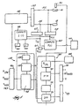
- Fig. 1 shows a system 10 for ablating human tissue that embodies the features of the invention.
- the system 10 includes a generator 12 that delivers radio frequency energy to ablate tissue.
- a generator 12 that delivers radio frequency energy to ablate tissue.
- other types of energy can be generated for tissue ablating purposes.
- the system 10 also includes a steerable catheter 14 carrying a radio frequency emitting ablation electrode 16.
- the ablation electrode 16 is made of platinum.
- the system 10 operates in a unipolar mode.
- the system 10 includes a skin patch electrode that serves as an indifferent second electrode 18.
- the indifferent electrode 18 attaches to the patient's back or other exterior skin area.
- the system 10 can be operated in a bipolar mode.
- the catheter 14 carries both electrodes.
- the system 10 can be used in many different environments. This specification describes the system 10 when used to provide cardiac ablation therapy.
- a physician steers the catheter 14 through a main vein or artery (typically the femoral vein or artery) into the interior region of the heart that is to be treated.
- the physician then further manipulates the catheter 14 to place the electrode 16 into contact with the tissue within the heart that is targeted for ablation.
- the user directs radio frequency energy from the generator 12 into the electrode 16 to ablate and form a lesion on the contacted tissue.
- the catheter 14 includes a handle 20, a guide tube 22, and a distal tip 24, which carries the electrode 16.
- the handle 20 encloses a steering mechanism 26 for the catheter tip 24.
- a cable 28 extending from the rear of the handle 20 has plugs (not shown). The plugs connect the catheter 14 to the generator 12 for conveying radio frequency energy to the ablation electrode 16.
- Left and right steering wires extend through the guide tube 22 to interconnect the steering mechanism 26 to the left and right sides of the tip 24. Rotating the steering mechanism 26 to the left pulls on the left steering wire, causing the tip 24 to bend to the left. Also, rotating the steering mechanism 26 to the right pulls on the right steering wire, causing the tip 24 to bend to the right. In this way, the physician steers the ablation electrode 16 into contact with the tissue to be ablated.
- the ablation electrode 16 carries at least one temperature sensing element 30.
- the power that the generator 12 applies to the electrode 16 is set, at least in part, by the temperature conditions sensed by the element 30.
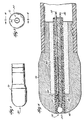
- the ablation electrode 16 includes an interior well 32 at its tip end.
- the temperature sensing element 30 occupies this well 32.
- the temperature sensing element 30 includes a small bead thermistor 34 with two associated lead wires 36 and 38.
- the temperature sensing tip of the thermistor 34 is exposed at the tip end of the ablation electrode 16 for tissue contact.
- the thermistor 34 of the type shown is commercially available from the Fenwal Co. (Massachusetts) under the trade designation 111-202CAK-BD1.
- the lead wires 36 and 38 comprise #36 AWG signal wire Cu+ clad steel (heavy insulation).
- Potting compound 40 encapsulates the thermistor 34 and lead wires 36 and 38 within the electrode well 32. Insulating sheaths 42 also shield the encapsulated lead wires 36 and 38. Together, the compound 40 and sheaths 42 electrically insulate the thermistor 34 from the surrounding ablation electrode 16.
- the potting compound 40 and insulation sheathes 42 can be made with various materials.
- loctite adhesive serves as the potting compound 40, although another cyanoacrylate adhesive, an RTV adhesive, polyurethane, epoxy, or the like could be used.
- the sheathes 42 are made from polyimide material, although other conventional electrical insulating materials also can be used.
- a thermal insulating tube 44 envelopes the encapsulated thermistor 34 and lead wires 36 and 38.
- the thermal insulation tube 44 can itself be adhesively bonded to the interior wall of the well 32.
- the thermal insulating material of the tube 44 can vary. In the illustrated embodiment, it is a polyimide material having a wall thickness of about .076 mm (.003 inch). Other thermal insulating materials like mylar or kapton could be used.
- the lead wires 36 and 38 for the thermistor 34 extend through the guide tube 22 and into the catheter handle 20. There, the lead wires 36 and 38 electrically couple to the cable 28 extending from the handle 20.
- the cable 28 connects to the generator 12 and transmits the temperature signals from the thermistor 34 to the generator 12.
- the handle 20 carries a calibration element R CAL for the thermistor 34.
- the element R CAL accounts for deviations' in nominal resistance among different thermistors.
- the resistance of thermistor 34 is measured at a known temperature; for example, 75 degrees C.
- the calibration element R CAL has a resistance value equal to the measured value. Further details of this will be discussed later.
- the generator 12 includes a radio frequency power source 48 connected through a main isolation transformer 50 to outlet and return lines 52 and 54.
- Outlet line 52 leads to the ablation electrode 16.
- Return line 54 leads from the indifferent electrode 18.
- the power source 48 when used for cardiac ablation, is typically conditioned to deliver up to 50 watts of power at a radio frequency of 500 kHz.
- the generator 12 further includes a first processing stage 56.
- the first processing stage 56 receives as inputs an instantaneous power signal P (t) , a set temperature value T SET , and a temperature control signal T CONTROL . Analyzing these inputs using prescribed criteria, the first processing stage 56 derives a demand power signal P DEMAND .
- the generator 12 also includes a second processing stage 58.
- the second processing stage 58 receives as input the demand power signal P DEMAND from the first processing stage 56.
- the second processing stage 58 also receives as inputs the instantaneous power signal P (t) and a maximum power value P MAX . Analyzing these inputs according to prescribed criteria, the second processing stage 58 adjusts the amplitude of the radio frequency voltage of the source, thereby adjusting the magnitude of the generated power, which P (t) represents.
- the generator 12 preferably includes an interactive user interface 13, which is only generally shown in schematic form in Fig. 1. It should be appreciated that the interface 13 can, in conventional ways, make full use of conventional input devices (for example, a key board or mouse); output display devices (for example, a graphics display monitor or CRT); and audio and visual alarms.
- the generated power signal P (t) input for the first processing stage 56 is generated by a multiplier 60.
- the multiplier 60 receives an instantaneous current signal I (t) from an isolated current sensing transformer 62 and an instantaneous voltage signal V (t) from an isolated voltage sensing transformer 64.
- the isolated current sensing transformer 62 is electrically coupled to the return line 54.
- the transformer 62 measures the instantaneous radio frequency current I (t) emitted by the ablation electrode 16 through body tissue to the indifferent electrode 18.
- the isolated voltage sensing transformer 64 is electrically coupled between the outlet and return lines 52 and 54.
- the voltage sensing transformer 64 measures the instantaneous radio frequency voltage V (t) across body tissue between the ablation electrode 16 and the indifferent electrode 18.
- the multiplier 60 multiples I (t) by V (t) to derive the instantaneous radio frequency power P (t) , which passes through the low pass filter 61 to eliminate ripple.
- the filtered P (t) serves as the power input signal for the first processing stage 56.
- the generator 12 includes, as part of its overall interface 13, a display 110 (see Fig. 1 also) to show P (t) .
- the set temperature value T SET for the first processing stage 56 can be inputted by the physician through an interface 66, which is part of the overall interface 13 of the generator 12 (see Fig. 1 also) .
- the set temperature value T SET represents the temperature the physician wants to maintain at the ablation site.
- the value T SET can be established in other ways. For example, the value T SET can vary over time to define a set temperature curve. Further details of this will be described later.
- the set temperature value T SET selected depends upon the desired therapeutic characteristics of the lesion. Typical therapeutic lesion characteristics are the surface area of the tissue that is ablated and depth of the ablation. Typically, the set temperature T SET is in the range of 50 to 90 degrees C.
- the temperature control signal T CONTROL input is based upon the actual instantaneous temperature conditions sensed T M(t) by the sensing element 30.
- the first processing stage 56 receives as T CONTROL the output resistance value of the thermistor 34 (in ohms). It divides this resistance value by the calibration value R CAL to normalize the resistance value of the thermistor 34.
- This normalized resistance value is the input to a read only memory (ROM) table in the generator 12, which contains stored thermistor temperature data.
- the ROM output is the actual measured temperature T M(t) (in degrees C).
- the T M(t) output is preferably shown in a display 68, which is part of the overall interface 13 for the generator 12 (see Fig. 1 also).
- the actual instantaneous temperature T M(t) can be used directly by the first processing stage 56.
- the first processing stage 56 includes a predicted temperature processor 70 (PTP).
- the PTP 70 derives from T M(t) a predicted temperature value (designated T PRED(t) ).
- the PTP 70 continuously samples T M(t) over prescribed sample periods ⁇ T SAMPLE . Applying prescribed criteria to these samples, the PTP 70 predicts at the end of each sample period a temperature condition T PRED(t) that would exist at the end of a future time period (greater than ⁇ T SAMPLE ), assuming that power supplied to the ablating electrode 16 is not changed. This future time period is called the prediction period ⁇ T PREDICT ,
- the length of the prediction period ⁇ T PREDICT can vary. Its maximum length depends largely upon the thermal time constant of the tissue, to take into account the expected physiological response of the tissue to temperature conditions generated during ablation.
- the prediction period ⁇ T PREDICT should not exceed the time period at which the tissue can be expected to experience cellular transformation when exposed to ablating heat.
- the thermal time constant is such that the maximum length of the prediction period ⁇ T PREDICT should typically not exceed about two seconds. After about two seconds, cardiac tissue can be expected to begin experiencing cellular transformation when exposed to the range of temperatures generated during ablation.
- ⁇ T SAMPLE is selected to be smaller than ⁇ T PREDICT .
- the PTP 70 measures the instantaneous temperature T M(t) at the end of the present sample period and compares it to the measured temperature at the end of one or more preceding sample periods T M(t-n) , where n is the number of preceding sample periods selected for comparison.
- ⁇ T PREDICT is selected to be 0.48 second
- n is selected to be 1. That is, the PTP 70 takes into account T M(t) for the instant sample period (t) and T M(t-1) for the preceding sample period (t-1).
- T PRED(t) 25 T M ( t ) -24 T M ( t -1)
- the PTP 70 includes a low pass filter 72 with a selected time constant ( ⁇ ).
- the PTP 70 averages T PRED(t) through the filter 72 before supplying it to a demand power processor DPP 76, which will be described later.
- the time constant ( ⁇ ) of the filter 72 selected can vary, according to the degree of accuracy desired. Generally speaking, a mid-range time constant ( ⁇ ) of about 0.2 second to about 0.7 second will provide the required accuracy. In the above described representative implementation, a time constant ( ⁇ ) of 0.25 second is used.
- the degree of accuracy of the PTP 70 can also be altered by varying K. More particularly, by lowering the value of K, one can expect the PTP 70 to achieve a greater degree of accuracy in predicting the future temperature T PRED(t)
- the value of K can be varied by selecting values for ⁇ T SAMPLE or ⁇ T PREDICT , or both. Preferably, the value of K is varied by selecting ⁇ T PREDICT .
- the degree of accuracy PTP 70 can also be improved, if desired, by selecting greater values for n; that is, by taking into account more past values of T M(t) in calculating T PRED(t) .
- the PTP 70 includes a user interface 74, which is part of the overall interface 13 of the generator 12 (see Fig. 1 also). Using the interface 74, the physician can select and modify the sampling history (n); the prediction period ⁇ T PREDICT ; and the time constant ( ⁇ ) in real time, on line.
- the ability to vary the accuracy of the PTP 70 in calculating T PRED(t) with on line changes provides flexibility in adapting the first processing stage 56 to differing ablating conditions.
- the first processing stage 56 further includes a demand power processor (DPP) 76.
- the DPP 76 periodically compares T PRED(t) to the set temperature value T SET . Based upon this comparison, and taking into account the magnitude of the instantaneous power P (t) supplied to the ablating electrode 16, the DPP 76 derives the demand power output P DEMAND .
- the DPP76 also takes into account other system operating goals and criteria, like response time, steady state temperature error, and maximum temperature overshoot.
- the demand power output P DEMAND of the first processing stage 56 represents the magnitude of the radio frequency power that should be supplied to the ablating electrode 16 to establish or maintain the desired local temperature condition T SET at the ablating electrode 16.
- the manner in which the DPP 76 derives P DEMAND can vary. For example, it can employ proportional control principles, proportional integral derivative (PID) control principles, adaptive control, neural network, and fuzzy logic control principles.
- PID proportional integral derivative
- the DPP 76 employs a modified velocity PID control technique specially adapted for cardiac ablation. Using this technique, the DPP 76 controls the magnitude of P DEMAND based upon a fixed value of T SET established by the physician.
- the DPP 76 compares a derived operating value V D to a preselected set value (V S ) for the operating condition.
- f is a N-variable nonlinear function that the DPP 76 follows in performing its processing function.
- ⁇ 1 , ⁇ 2 , ⁇ 3 , ... , ⁇ N are the values of the error signal ⁇ at N different moments of time.
- the DPP 76 thereby adjusts the power by an increment based upon a nonlinear function of the present and past values of the error signal ⁇ .
- the desired error E (t) to be maintained is zero.
- Other desired error values could be used.
- Using the asymmetric scaling factor S provides the desired nonlinear response f( ⁇ ) over time to maintain the desired error E (t) .
- the f( ⁇ ) of the DPP 76 decreases power faster (when T PRED(t) > T SET ) than increasing power (when T PRED(t) ⁇ T SET ).
- the DPP 76 uses fixed values for the coefficients K p , K i , and K d , regardless of the particular ablating conditions.
- the calculation for P DEMAND can be adapted on line by the physician to changing ablating conditions encountered, by adjusting the front end calculation of T PRED(t) by the PTP 70. Because of the flexibility to make on line adjustments that the PTP 70 provides, multiple value tables of K p , K i , and K d are not necessary in the system to accommodate changes in ablating conditions.
- K p 0.025375
- K i 97.0695
- K d 7.82 x 10 -5
- This representative implementation adjusts P DEMAND(t) to reach T SET ⁇ 3° C within 5.0 seconds, if not limited by available power. It also aims to keep a peak steady state temperature error (defined as T SET - T PRED(t) ) of less than 3° C. The implementation also adjusts P DEMAND(t) over time to avoid overshooting T SET by more than 3° C.
- the DPP 76 uses modified velocity PID control described above to control the magnitude of P DEMAND based upon varying values of T SET over time.
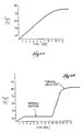
- T SET is expressed as a function with respect to time (see Figs. 6A and 6B), which can be linear or nonlinear or both.
- T SET comprises a temperature versus time curve (see Figs. 6A and 6B) for heating tissue. The curve has a first temperature value set at a first time period and at least one additional temperature value, different than the first temperature value, set at a second time period after the first time period.
- the T SET defines a complex curve to accommodate thermal mapping before thermal ablation.
- T SET again begins to be expressed in term of a nonlinear function, and the slope flattens out as T SET approaches a second preselected value for tissue ablation.
- the first value of T SET for thermal mapping is within 45° C to 50° C
- the second value for T SET for tissue ablation is within 50° C to °90 C, and preferable about 70 C.
- T SET can be defined as a true function of time.
- the DPP 76 receives as input changing values of T SET over time, which define the prescribed set temperature curve.
- the system calculates E (t) based upon these changing values to derive P DEMAND , in the same manner that the system derives P DEMAND based upon a constant value of T SET .
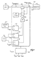
- Fig. 7 shows an alternative implantation of the DPP 76, which derives P DEMAND using adaptive control principles.
- the DPP 76 receives as input T SET and T PRED in the manner previously described.
- the values of T SET can be fixed or can vary with time, as also previously described.
- the DPP 76 further includes a pair of adaptive filters 78 and 80.
- Each filter 78 and 80 generates an output based upon an input, expressed in terms of an assumed relationship between them.
- the output comprises an estimate, based upon the assumed relationship, of an external condition that can be independently measured by the DPP 76.
- the DPP 76 compares the estimated output to the actually measured external condition and adjusts the coefficients of the assumed relationship to minimize the error between the two.
- the filter 78 receives as input the instantaneous power P (t) applied by the RF source 48 to the ablating electrode 16.
- the filter 78 generates as output an estimate of the temperature condition T EST(t) that the sensing element 30 should sense, given P (t) and the assumed relationship between P (t) and the temperature T (t) at the ablation site.
- the filter 78 therefore approximates the heat transfer function of the tissue contacting the ablating electrode 16.
- the DPP 76 includes a summing junction 82, which derives a temperature error signal T E by subtracting the estimated temperature T EST(t) from the temperature T (t) actually sensed by the sensing element 30.
- the DPP 76 feeds back the error signal T E to the filter 78.
- the filter 78 adjusts the coefficients of the assumed relationship between P (t) and T (i) to minimize the magnitude of the error T E .
- the filter 78 uses a finite linear sequence to express the assumed relationship between P (i) and T (i) .
- the sequence estimates a future temperature T EST(t+1) based upon present instantaneous power P (t) and the past power P (t-n) , where n represents the number of past power conditions taken into account.
- the quantity n can vary according to the accuracy desired.
- the assumed transfer coefficients comprise initially selected values which are then adjusted to minimize the error signal T E .
- This adaptive adjustment can be accomplished using various known techniques. For example, the coefficients can be adjusted based upon the Least Mean Square (LMS) method, which tends to minimize the square of the error T E .
- LMS Least Mean Square
- a larger ⁇ provides a faster convergence rate but a larger ripple about the optimal coefficients.
- a smaller ⁇ reduces both the convergence rate and the ripple about the optimal solution.
- the optimal value of ⁇ depends on the characteristics of the system to be modeled. In the case of the illustrated electrode-blood-tissue system, ⁇ lies in the interval between 0.01 and 0.5.
- the filter 80 is the inverse of the filter 78.
- the filter 80 receives as input a temperature error signal ⁇ T generated by the summing junction 84.
- the summing junction 84 subtracts T PREDICT(t) from T SET to generate the error signal ⁇ T.
- the filter 80 generates as output ⁇ P, which represents an approximation of how much the power P (t) should be altered in view of ⁇ T, based upon the inverse of the assumed relationship between power P (t) and temperature T (t) that the filter 78 uses.
- ⁇ P represents an approximation of how much the power P (t) should be altered in view of ⁇ T, based upon the inverse of the assumed relationship between power P (t) and temperature T (t) that the filter 78 uses.
- the filter 80 adjusts its coefficients in relation to the adjustments made by the filter 78 to the coefficients a and b, based upon the error signal T E of the summing junction 82, to minimize the magnitude of this error signal T E .
- the output ⁇ P of the filter 80 is fed through another summing junction 86, which is initialized at the outset of the ablation procedure at the beginning power level P 0 .
- the summing junction 86 continuously adjusts the beginning power value with the ⁇ P output of the inverse filter 80.
- the output of the summing junction 86 therefore comprises P DEMAND .
- the DPP 76 shown in Fig. 7 sends the output P DEMAND to the second processing stage 58 to modify P (t) .
- the temperatures measured by the sensing element 30 may not correspond exactly with the actual maximum tissue temperature. This is because the region of hottest temperature occurs beneath the surface of the tissue at a depth of about 0.5 to 1.0 mm from where the energy emitting electrode 16 (and the sensing element 30) contacts the tissue. If the power is applied to heat the tissue too quickly, the actual maximum tissue temperature in this region may exceed 100° C and lead to tissue desiccation.
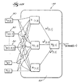
- Fig. 11A shows an alternative embodiment of the DPP 76 which derives P DEMAND using neural network control principles.
- the PTP 70 receives as input a predicted temperature of the hottest tissue region T MAXPRED(t) from a neural network predictor 200.
- the DPP 76 derives P DEMAND(t+1) based upon the difference between this T MAXPREDICT(t) and T SET .
- the values of T SET can be fixed, or they can vary with time, as previously described.
- the predictor 200 comprises a two-layer neural network, although more hidden layers could be used.
- the predictor 200 includes a first and second hidden layers and four neurons, designated N (L,X) , where L identifies the layer 1 or 2 and X identifies a neuron on that layer.
- the output neuron N (2,1) of the second layer receives as inputs the weighted outputs of the neurons N (1,1) ; N (1,2) ; and N (1,3) .
- the predictor 200 must be trained on a known set of data that have been previously acquired experimentally. For example, using a back-propagation model, the predictor 200 can be trained to predict the known hottest temperature of the data set with the least error. Once the training phase is completed, the predictor 200 can be used to predict T MAXPRED(t) .
- the first processing stage 56 can use a single neural network 201 to derive P DEMAND(t) .
- the network 201 receive as input, in addition to k past samples of temperatures from the sensor 30, the value of T SET , and the current power P (t) .
- the network 201 derives P DEMAND(t) as output, which reflects the power level required to keep the hottest predicted temperature at or about T SET .
- a set of data containing a solution based upon all the desired inputs is necessary to train the neural network of the predictor 201 to manipulate the input and obtain the desired output with the least amount of error.
- Fig. 12 shows an alternative embodiment of the first processing stage 56 which derives P DEMAND using fuzzy logic control principles.
- the first processing stage 56 includes a fuzzifier 202, which receives as inputs the temperature signals T M(t) from the sensor 30.
- the fuzzifier 202 also receives T SET as input, either as a constant value or a value that changes over time.
- the fuzzifier 202 converts the T M(t) input data to fuzzy inputs based upon reference to T SET on a relative basis.
- the fuzzy inputs can determine the degree (or membership function) to which a given T M(t) is, compared to T SET , "cool" or "warm” or “warmer” or "hot".
- fuzzy inputs are passed through an I/O mapper 204 which converts them to fuzzy outputs by translating the inputs into descriptive labels of power. This is accomplished, for example, by using linguistic "if... then” rules, like "if the fuzzy input is ... then the fuzzy output is ." Alternatively, more complex mapping matricial operators can be used.
- T M(t) is "cool, " the I/O mapper 204 outputs the descriptive label "Largest Positive,” to indicate that a large relative increase in power is required.
- T M(t) is "hot,” the I/O mapper 204 outputs the descriptive label “Largest Negative,” to indicate that large relative decrease in power is required.
- the intermediate fuzzy inputs "warm” and “warmer” produce intermediate descriptive labels as fuzzy outputs, such as “Smallest Positive” and “Smallest Negative. "
- the defuzzifier 206 also receives actual power P (t) as an input, since the fuzzy outputs refer to variations in P (t) . Based upon P (t) and the variations required based upon the fuzzy outputs, the defuzzifier 206 derives P DEMAND(t) .
- the fuzzy logic controller may be trained on a known set of data before use.
- the second processing stage 58 includes a converter 112.
- the converter 112 derives a command voltage signal V DEMAND(t) based upon a power input signal to adjust the amplitude of the voltage V (t) supplied to the source 48 to thereby adjust P (t) .
- the converter 112 could derive a command current signal I DEMAND(t) based upon a power input signal to adjust the amplitude of the current supplied to the source 48, achieving the same results.
- the power input to the converter 112 could comprise P DEMAND(t) as derived by the DPP 76.
- the second processing stage 58 includes a demand power down stage 94 between the DPP 76 and the converter 112.
- the power down stage 94 receives P DEMAND(t) as input and generates a modified demand power signal MP DEMAND(t) , taking into account one or more other operating conditions then existing.
- the converter 112 receives MP DEMAND(t) as its input.
- the power down stage 94 monitors certain operating conditions of the electrode.
- the power down stage 94 compare the monitored conditions with preselected criteria for the second operating condition and generate an error signal when the second operating condition fails to meet the preselected criteria.
- the power down stage 94 modifies P DEMAND(t) in a non-linear fashion to set MP DEMAND(t) at a prescribed low demand power output value P LOW .
- the power down stage 94 retains the value of P DEMAND(t) as the value of MP DEMAND(t) .
- P LOW is selected to be above zero, but preferably below the power level at which tissue ablation occurs. In the illustrated and preferred embodiment, P LOW is about 1 watt.
- the power down stage 94 sets the value of MP DEMAND(t) in a nonlinear fashion back to the value of P DEMAND(t) as soon as the operating conditions giving rise to the power down mode cease.
- the power down stage 94 responds to prescribed power or temperature conditions.
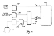
- Fig. 8 schematically shows a preferred implementation of the power down stage 94.
- the power down stage 94 includes microswitches 108 and 110.
- Microswitch 108 receives as input P DEMAND(t) from the DPP 76 (see Fig. 5, also).
- the microswitch 110 receives as input the value of P LOW .
- An output line 114 connects the converter 112 in parallel to the outputs of the switches 108 and 110.
- the power down stage also includes three comparators 114, 116, and 118. Each comparator 114, 116, and 118 independently controls the microswitches 108 and 110, taking into account different operating conditions.
- the outputs of the comparators 114, 116, and 118 are connected to OR gate 122.
- An output switch line S leads to the microswitch 108, while a negate switch line S NEG leads to microswitch 110.
- the output of the comparator 114 takes into account prescribed maximum power conditions.
- the comparator 114 receives current instantaneously power P (t) as its (+) input and a prescribed maximum power value P MAX as its inverse or (-) input.
- the comparator 114 compares P (t) to the prescribed maximum power value P MAX .
- An error free condition exists when P (t) ⁇ P MAX .
- the comparator 114 sets microswitch 108 closed and microswitch 110 open.
- the microswitch 108 passes through the value of P DEMAND(t) as the output MP DEMAND(t) .
- the value of P MAX can vary according to the particular requirements of the ablation procedure.
- the generator 12 can include, as part of its overall interface 13, an interface 96 for the physician to select and adjust P MAX (see Fig. 1 also).
- P MAX should lie in the range of about 50 watts to about 200 watts, with P MAX increasing as the surface area of the ablating electrode increases.
- the value of P MAX can also be set, not upon direct power input settings by the physician, but rather upon the physical and/or functional characteristics of the ablating electrode being used, or both.
- the physical and/or functional characteristics of the ablating electrode can include surface area, electrode configuration, electrode orientation, and electrode field dispersion properties. For example, an electrode with a smaller surface area can usually be expected to be operated at lower power settings.
- the relationships among electrode type and P MAX can be determined by empirical testing.
- the test results can be transcribed in a look-up power criteria table 102 resident in ROM of the generator 12 (as Fig. 9 shows).
- the power down stage 94 includes a register 98 for automatically setting P MAX based upon the power criteria transcribed in the look-up table 102.
- the register 98 includes an input 100 (which is part of the overall interface 13 of the generator, as Fig. 1 also shows) for the physician to enter the electrode type being used.
- the register 98 then automatically sets P MAX in the second processing stage 58 based upon the power criteria table 102.
- the catheter 14 can itself carry means for automatically producing an identification signal representing the electrode type when the catheter 14 is connected to the generator 12.
- the signal uniquely identifies the particular physical and/or performance characteristics of the connected electrode 16.
- a data acquisition element 106 queries and reads the identification signal of the catheter 14 to identify the electrode type. The element 106 then refers to the look-up table 102 to automatically set P MAX via the register 98.
- the means for automatically generating the electrode-type identification signal can vary.
- Fig. 10 shows a preferred arrangement.
- the catheter handle 20 carries a resistor R having a prescribed ohm value.
- the ohm value of R represents the sum of calibration resistance value R CAL (as previously described) and a selected add-on resistance value R I .
- the calibration resistance R CAL is a fixed value, depending upon the thermistor 34 the catheter 14 carries.
- the magnitude of the add-on value R I varies in predetermined increments depending upon the electrode type.
- a Type 1 Electrode is assigned an add-on value R I of 5000 ohms; a Type 2 Electrode is assigned an add-on value R I of 10,000 ohms; a Type 3 Electrode is assigned an add-on value R I of 15,000 ohms, and so on.
- the handle 20 for a Type 1 Electrode will carry a resistor R of 9000 ohms (4000 ohms calibration resistance R C plus 5000 ohms add-on resistance R I ); the handle 20 for a Type 2 Electrode will carry a resistor R of 14,000 ohms (4000 ohms calibration resistance R C plus 10,000 ohms add-on resistance R I ); and the handle 20 for a Type 3 Electrode will carry a resistor R of 19,000 ohms (4000 ohms calibration resistance R C plus 15,000 ohms add-on resistance R I ).
- a look-up table 104 in the data acquisition element 106 (shown in Fig. 9) stores the fixed value R CAL of the calibration resistance, the range of add-on resistances R I corresponding to the identified electrode types, and their sum (which is the value of the resistor R that the system actually senses).
- the element 106 When connected to the generator 12 the element 106 senses the total ohm value of the resistor R in the handle 20.
- the element 106 refers to the look-up table 104.
- a sensed total resistance R of less than 10,000 ohms identifies a Type 1 Electrode
- a sensed total resistance R of 10,000 ohms to 15,000 ohms identifies a Type 2 Electrode
- a sensed total resistance R of over 15,000 ohms up to 20,000 ohms identifies a Type 3 Electrode.
- the element 106 then refers to the power criteria look-up table 102 to obtain the corresponding power condition.
- the register 98 automatically sets P MAX in the power down stage 94.
- the data acquisition element 106 subtracts the known add-on value for the identified Electrode Type. In this way, the generator 12 also derives the value of the calibration resistance R CAL for the thermistor 34. As already described (and as Fig. 5 shows), the first processing stage 56 processes the calibration resistance and the resistance sensed by the thermistor to derive the temperature T M(t) , as previously described.
- the handle can carry a solid state micro-chip, ROM, EEROM, EPROM, or nonvolatile RAM.
- the micro-chip can be pre-programmed with digital values representing the calibration resistance for the thermistor 34 (or the calibration resistances for the multiple thermistors) and the appropriate value representing the Electrode Type. In this arrangement, the micro-chip outputs these values to the register 98, when queried by the data acquisition element 106.
- the output of the comparator 116 responds to prescribed maximum absolute temperature conditions.
- the comparator 116 receives at its (+) input the temperature value T PRED(t) from the PTP 70.
- the comparator 116 receives as its inverse or (-) input a prescribed maximum temperature value T MAX .
- the comparator 116 compares T PRED(t) to the prescribed maximum temperature value T MAX .
- An error-free condition exists when T PRED(t) ⁇ T MAX .
- the comparator 116 sets microswitch 108 closed and microswitch 110 open.
- the microswitch 108 passes through the value of P DEMAND(t) as the output MP DEMAND(t) .
- T PRED(t) ⁇ T MAX An error condition exists when T PRED(t) ⁇ T MAX .
- the comparator 116 sets the microswitch 108 open and microswitch 110 closed.
- the microswitch 108 blocks passage of the value of P DEMAND(t) , and P LOW becomes the output MP DEMAND(t) .
- the stage 94 reduces P DEMAND(t) to P LOW in an instantaneous, nonlinear fashion.
- T MAX can be prescribed in various ways. It can, for example, be a selected absolute value that the physician inputs. For cardiac ablation, the value of T MAX is believed to lie in the range of 80° C and 95° C, with a preferred representative value of about 90° C.
- INCR can vary, just as T SET can vary, according to the judgment of the physician and empirical data.
- a representative value of INCR for cardiac ablation is believed to lie in the range of 2° C to 8° C, with a preferred representative value of about 5° C.
- the comparator 118 like the comparator 116, receives at its (+) input the temperature value T PRED(t) from the PTP 70.
- the comparator 118 receives as its inverse or (-) input the prescribed incremental temperature value T INCR .
- the comparator 116 compares T PRED(t) to the prescribed incremental temperature value T INCR .
- An error-free condition exists when T PRED(t) ⁇ T INCR .
- the comparator 118 sets microswitch 108 closed and microswitch 110 open.
- the microswitch 108 passes through the value of P DEMAND(t) as the output MP DEMAND(t) .
- T PRED(t) ⁇ T INCR An error condition exists when T PRED(t) ⁇ T INCR .
- the comparator 116 sets the microswitch 108 open and microswitch 110 closed.
- the microswitch 108 blocks passage of the value of P DEMAND(t) , and P LOW becomes the output MP DEMAND(t) .
- the stage 94 reduces P DEMAND(t) to P LOW in an instantaneous, nonlinear fashion.
- any comparator 114, 116, or 118 opens switch 108 and closes switch 110 (i.e., when at least one error condition exists), P LOW is instantaneously set as MP DEMAND(t) . Under this condition, the converter 112 receives P LOW as MP DEMAND(t) . If none of the comparators 114, 116, or 118 opens switch 108 and closes switch 110, the converter 112 receives P DEMAND(t) as MP DEMAND(t) .
- the manner in which the converter 112 of the second processing stage 58 generates V DEMAND(t) to adjust P (t) can vary.
- the converter 112 can employ proportional control principles, proportional integral derivative (PID) control principles, neural network, fuzzy logic, and adaptive control principles.
- the converter 112 employs known PID principles to derive V DEMAND .
- the converter 112 compares MP DEMAND(t) to the generated power signal P (t) , which it receives from the multiplier 60.
- the converter 112 also takes into account the changes of the generated power signal P (t) over time. Based upon these considerations, the converter 112 of the second processing stage 58 derives the demand voltage signal V DEMAND .
- the generator 12 preferably includes an impedance microprocessor 88.
- the impedance microprocessor 88 receives the instantaneous current signal I (t) and the instantaneous voltage signal V (t) from the sensing transformers 62 and 64, already described.
- the generator 12 includes a display 90 as part of its overall interface 13 to show the measured impedance Z (t) (see Fig. 1 also).
- the microprocessor 88 also preferably maintains a record of sampled impedances Z (t) over time. From this, the microprocessor calculates the changes in impedance during a selected interval and generates appropriate control signals based upon predetermined criteria. Even when the power down stage 94 sets P DEMAND(t') as P LOW to stop tissue ablation, the microprocessor still serves to continuously compute Z (t) for the purposes set forth below.
- the microprocessor 88 For example, if measured impedance falls outside a predetermined set range, the microprocessor 88 generates a command signal to shut off power to the ablation electrode 16.
- the set range for impedance for a cardiac ablation procedure is believed to be about 50 to 300 ohms.
- impedance begins in the set range and, over time, increases beyond it, the most likely cause is coagulum formation on the ablation electrode 16.
- a sudden rise in impedance over the set range suggests the sudden onset of coagulum formation or a sudden shift in the position of the ablation electrode 16. Rapid fluctuations of the impedance also could suggest poor contact between the ablation electrode 16 and the targeted tissue. All require prompt response; for example, withdrawal and cleaning of the ablation electrode 16, or repositioning of the ablation electrode 16.
- the generator 12 preferably includes visual and auditory alarms 92 as part of its overall interface 13 (see Fig. 1 also), to transmit a warning to the user when these impedance-related conditions occur.
- a very high impedance value could suggest poor skin contact with the indifferent electrode 18, or an electrical problem in the generator 12. Again, this calls for prompt corrective action.
- the power down stage 94 rapidly reduces but does not shut down power, based upon prescribed instantaneous high power or high temperature conditions.
- the second processing stage 58 also includes an error shutdown stage 128.
- the error shutdown stage 128 responds to the persistence, over a set time period, of a prescribed over-temperature condition or conditions indicative of an actual or developing system failure.
- the error shutdown phase 128 turns off all power to the electrode 16.
- the error shutdown phase 128 can work separately from or in tandem with the power down mode.
- the power down stage 94 will not be triggered to set P LOW . Still, if this over-temperature situation persists for more than a prescribed period of time (for example, 2 to 5 seconds) , the second processing stage 58 can be conditioned to assume an actual or developing system failure, and institute a power shutdown.
- a prescribed period of time for example, 2 to 5 seconds
- the power down stage 94 will be triggered to set P LOW . If this over-temperature situation persists during the power down conditions for a prescribed period of time (for example, 2 to 5 seconds) , the second processing stage 58 can be conditioned to assume an actual or developing system failure, and institute a power shutdown.
- the generator 12 as described provides control over the ablation procedure.
- the monitoring and control of power assure the effective distribution of radio frequency energy to the ablation electrode 16, while setting safe physiological limits.
- the generator 12 can also include an alternative control mode based upon power. In this mode, the generator 12 seeks to maintain a set power condition, independent of measured temperature conditions. The generator 12 would switch to the power control mode, for example, when the electrode 16 in use does not carry a temperature sensing element 30, or upon selection by the physician, even when the electrode 16 has a temperature sensing element 30.
- micro-processor controlled components using digital processing to analyze information and generate feedback signals. It should be appreciated that other logic control circuits using micro-switches, AND/OR gates, invertors, and the like are equivalent to the micro-processor controlled components and techniques shown in the preferred embodiments.
Landscapes
- Health & Medical Sciences (AREA)
- Surgery (AREA)
- Life Sciences & Earth Sciences (AREA)
- Engineering & Computer Science (AREA)
- Medical Informatics (AREA)
- General Health & Medical Sciences (AREA)
- Nuclear Medicine, Radiotherapy & Molecular Imaging (AREA)
- Veterinary Medicine (AREA)
- Biomedical Technology (AREA)
- Heart & Thoracic Surgery (AREA)
- Public Health (AREA)
- Molecular Biology (AREA)
- Animal Behavior & Ethology (AREA)
- Otolaryngology (AREA)
- Physics & Mathematics (AREA)
- Plasma & Fusion (AREA)
- Cardiology (AREA)
- Surgical Instruments (AREA)
- Investigating Or Analysing Biological Materials (AREA)
- Laser Surgery Devices (AREA)
- Body Washing Hand Wipes And Brushes (AREA)
- Control Of Temperature (AREA)
Claims (17)
- Appareil pour fournir de l'énergie à une électrode (16) pour l'ablation d'un tissu comprenant
un premier élément (70) pour contrôler l'état d'une température de l'électrode (16) et pour en dériver une valeur de température prédite pour un temps futur VD,
un élément de traitement (76) pour comparer la valeur de température prédite dérivée VD à une valeur de température prédéfinie VS afin d'établir un signal d'erreur Δ, dans lequel :
un élément de sortie (58) pour fournir un signal de commande SCOMMAND afin de régler l'alimentation de l'électrode (16) au-dessus d'une valeur nulle, maintenant ainsi une alimentation sans interruption, dans lequel : - Appareil selon la revendication 1, dans lequel
- Appareil selon la revendication 1 ou 2, dans lequel VS reste essentiellement constante au fil du temps.
- Appareil selon la revendication 1 ou 2, dans lequel VS change au moins une fois en fonction du temps.
- Appareil selon la revendication 1, comprenant en outre
un générateur (48) adapté pour être électriquement couplé à l'électrode (16) pour fournir une énergie à l'électrode (16) pour l'ablation d'un tissu, et
un contrôleur couplé au générateur (48) pour fournir une alimentation au générateur (48), le contrôleur comprenant le premier élément (70), l'élément de traitement (76), et l'élément de sortie (58)
dans lequel l'élément de sortie (58) ajuste de manière incrémentielle l'alimentation fournie à l'électrode (16) selon l'expression suivante :ΔP est l'ajustement incrémentiel de la puissance ;g est une fonction mathématique ; etSSCALE est un facteur d'échelle non linéaire qui est égal à une première valeur X lorsque Δ > Z et est égal à une deuxième valeur Y, différente de X, lorsque Δ < Z, dans laquelle Z est un Δ souhaité. - Appareil selon la revendication 5, dans lequel Y > X.
- Appareil selon la revendication 5 ou 6, dans lequel Z = 0.
- Appareil selon la revendication 5, dans lequel le premier élément (70) comprend un élément de détection (30) pour mesurer une température de l'électrode (16) .
- Appareil selon la revendication 8, dans lequel le premier élément (70) contrôle les changements de température mesurés par l'élément de détection (30) au fil du temps pour dériver VD.
- Appareil selon la revendication 9, dans lequel VD comprend une prédiction de température pour un temps futur dérivée d'une ou plusieurs températures mesurées par l'élément de détection (30).
- Appareil selon la revendication 5, dans lequel VS reste essentiellement constante au fil du temps.
- Appareil selon la revendication 5, dans lequel VS change au moins une fois en fonction du temps.
- Appareil pour fournir de l'énergie à une électrode (16) pour l'ablation d'un tissu comprenant
un générateur (48) adapté pour être électriquement couplé à l'électrode (16) pour fournir de l'énergie à l'électrode (16) pour l'ablation du tissu, et
un contrôleur couplé au générateur (48) pour fournir une alimentation au générateur (48), le contrôleur comprenant
des premiers moyens d'échantillonnage (70) pour contrôler les conditions de fonctionnement, et
un premier élément de traitement (76) pour dériver un signal de commande d'alimentation SDERIVED basé sur un premier état de température contrôlé par les premiers moyens d'échantillonnage (70), caractérisé en ce que l'appareil comprend en outre :dans lequel, en l'absence du signal d'erreur E, SCOMMAND règle la puissance selon SDERIVED, etun deuxième élément de traitement (94) pour comparer une deuxième condition de fonctionnement contrôlée par les premiers moyens d'échantillonnage (70) avec un critère présélectionné pour la deuxième condition de fonctionnement et pour générer un signal d'erreur (E) lorsque la deuxième condition de fonctionnement ne remplit pas le critère prédéterminé, etun élément de sortie (58) pour fournir un signal de commande SCOMMAND afin de régler l'alimentation fournie au générateur (48),
dans lequel, lorsque le signal d'erreur E est généré, SCOMMAND règle l'alimentation selon une faible condition d'alimentation prescrite (PLOW), quel que soit SCOMMAND, PLOW étant une valeur supérieure à zéro. - Appareil selon la revendication 13, comprenant en outre :dans lequel PLOW est une valeur supérieure à zéro afin de permettre une dérivation de l'impédance par les deuxièmes moyens d'échantillonnage (88).des deuxièmes moyens d'échantillonnage (88) pour dériver l'impédance,
- Appareil selon la revendication 13 ou 14,
dans lequel la deuxième condition de fonctionnement contrôlée comprend une mesure de l'alimentation fournie au générateur (48), et
dans lequel le critère présélectionné comprend une valeur d'alimentation maximale établie. - Appareil selon la revendication 13 ou 14,
dans lequel la deuxième condition de fonctionnement contrôlée comprend une température prédite de l'électrode (16), et
dans lequel le critère présélectionné comprend une valeur de température maximale établie. - Appareil selon la revendication 13 ou 14,
dans lequel la deuxième condition de fonctionnement contrôlée comprend une température prédite de l'électrode (16), et
dans lequel le critère présélectionné comprend une valeur de température établie ajustée par une valeur incrémentielle établie.
Applications Claiming Priority (4)
| Application Number | Priority Date | Filing Date | Title |
|---|---|---|---|
| US267154 | 1981-05-26 | ||
| US26602394A | 1994-06-27 | 1994-06-27 | |
| US26715494A | 1994-06-28 | 1994-06-28 | |
| PCT/US1995/007960 WO1996000528A1 (fr) | 1994-06-27 | 1995-06-23 | Systemes et procedes de commande non lineaire permettant de chauffer des tissus humains et pratiquer leur ablation |
Publications (3)
| Publication Number | Publication Date |
|---|---|
| EP0767628A1 EP0767628A1 (fr) | 1997-04-16 |
| EP0767628A4 EP0767628A4 (fr) | 1998-05-06 |
| EP0767628B1 true EP0767628B1 (fr) | 2004-01-14 |
Family
ID=38657609
Family Applications (1)
| Application Number | Title | Priority Date | Filing Date |
|---|---|---|---|
| EP95924669A Expired - Lifetime EP0767628B1 (fr) | 1994-06-27 | 1995-06-23 | Systemes de commande non lineaire permettant de chauffer des tissus humains et pratiquer leur ablation |
Country Status (8)
| Country | Link |
|---|---|
| US (2) | US5755715A (fr) |
| EP (1) | EP0767628B1 (fr) |
| JP (1) | JP3682066B2 (fr) |
| AT (1) | ATE257675T1 (fr) |
| CA (1) | CA2194071C (fr) |
| DE (1) | DE69532447T2 (fr) |
| ES (1) | ES2216016T3 (fr) |
| WO (2) | WO1996000040A1 (fr) |
Families Citing this family (348)
| Publication number | Priority date | Publication date | Assignee | Title |
|---|---|---|---|---|
| US5906614A (en) * | 1991-11-08 | 1999-05-25 | Ep Technologies, Inc. | Tissue heating and ablation systems and methods using predicted temperature for monitoring and control |
| US6113591A (en) * | 1994-06-27 | 2000-09-05 | Ep Technologies, Inc. | Systems and methods for sensing sub-surface temperatures in body tissue |
| US6030379A (en) * | 1995-05-01 | 2000-02-29 | Ep Technologies, Inc. | Systems and methods for seeking sub-surface temperature conditions during tissue ablation |
| US6053912A (en) * | 1995-05-01 | 2000-04-25 | Ep Techonologies, Inc. | Systems and methods for sensing sub-surface temperatures in body tissue during ablation with actively cooled electrodes |
| US5837001A (en) * | 1995-12-08 | 1998-11-17 | C. R. Bard | Radio frequency energy delivery system for multipolar electrode catheters |
| US5665103A (en) * | 1996-03-07 | 1997-09-09 | Scimed Life Systems, Inc. | Stent locating device |
| US5755760A (en) * | 1996-03-11 | 1998-05-26 | Medtronic, Inc. | Deflectable catheter |
| US6126682A (en) | 1996-08-13 | 2000-10-03 | Oratec Interventions, Inc. | Method for treating annular fissures in intervertebral discs |
| EP0847729A1 (fr) * | 1996-12-12 | 1998-06-17 | Sulzer Osypka GmbH | Dispositif d'ablation pour traitement intra-cardiaque |
| US6063078A (en) * | 1997-03-12 | 2000-05-16 | Medtronic, Inc. | Method and apparatus for tissue ablation |
| US7992572B2 (en) | 1998-06-10 | 2011-08-09 | Asthmatx, Inc. | Methods of evaluating individuals having reversible obstructive pulmonary disease |
| US6634363B1 (en) | 1997-04-07 | 2003-10-21 | Broncus Technologies, Inc. | Methods of treating lungs having reversible obstructive pulmonary disease |
| US7027869B2 (en) | 1998-01-07 | 2006-04-11 | Asthmatx, Inc. | Method for treating an asthma attack |
| US6033399A (en) | 1997-04-09 | 2000-03-07 | Valleylab, Inc. | Electrosurgical generator with adaptive power control |
| US6012457A (en) | 1997-07-08 | 2000-01-11 | The Regents Of The University Of California | Device and method for forming a circumferential conduction block in a pulmonary vein |
| US5971983A (en) | 1997-05-09 | 1999-10-26 | The Regents Of The University Of California | Tissue ablation device and method of use |
| US6024740A (en) | 1997-07-08 | 2000-02-15 | The Regents Of The University Of California | Circumferential ablation device assembly |
| US6869431B2 (en) | 1997-07-08 | 2005-03-22 | Atrionix, Inc. | Medical device with sensor cooperating with expandable member |
| US6500174B1 (en) | 1997-07-08 | 2002-12-31 | Atrionix, Inc. | Circumferential ablation device assembly and methods of use and manufacture providing an ablative circumferential band along an expandable member |
| US6164283A (en) | 1997-07-08 | 2000-12-26 | The Regents Of The University Of California | Device and method for forming a circumferential conduction block in a pulmonary vein |
| US6997925B2 (en) * | 1997-07-08 | 2006-02-14 | Atrionx, Inc. | Tissue ablation device assembly and method for electrically isolating a pulmonary vein ostium from an atrial wall |
| US6514249B1 (en) | 1997-07-08 | 2003-02-04 | Atrionix, Inc. | Positioning system and method for orienting an ablation element within a pulmonary vein ostium |
| US6652515B1 (en) | 1997-07-08 | 2003-11-25 | Atrionix, Inc. | Tissue ablation device assembly and method for electrically isolating a pulmonary vein ostium from an atrial wall |
| US6245064B1 (en) | 1997-07-08 | 2001-06-12 | Atrionix, Inc. | Circumferential ablation device assembly |
| US6966908B2 (en) | 1997-07-08 | 2005-11-22 | Atrionix, Inc. | Tissue ablation device assembly and method for electrically isolating a pulmonary vein ostium from an atrial wall |
| US6007532A (en) * | 1997-08-29 | 1999-12-28 | 3M Innovative Properties Company | Method and apparatus for detecting loss of contact of biomedical electrodes with patient skin |
| US6231569B1 (en) * | 1997-10-06 | 2001-05-15 | Somnus Medical Technologies, Inc. | Dual processor architecture for electro generator |
| US6645200B1 (en) | 1997-10-10 | 2003-11-11 | Scimed Life Systems, Inc. | Method and apparatus for positioning a diagnostic or therapeutic element within the body and tip electrode for use with same |
| US6464699B1 (en) | 1997-10-10 | 2002-10-15 | Scimed Life Systems, Inc. | Method and apparatus for positioning a diagnostic or therapeutic element on body tissue and mask element for use with same |
| ATE423523T1 (de) * | 1997-10-23 | 2009-03-15 | Arthrocare Corp | Energiezufuhr für elektrochirurgie in leitenden fluiden |
| US7921855B2 (en) | 1998-01-07 | 2011-04-12 | Asthmatx, Inc. | Method for treating an asthma attack |
| US6558378B2 (en) * | 1998-05-05 | 2003-05-06 | Cardiac Pacemakers, Inc. | RF ablation system and method having automatic temperature control |
| US6837885B2 (en) | 1998-05-22 | 2005-01-04 | Scimed Life Systems, Inc. | Surgical probe for supporting inflatable therapeutic devices in contact with tissue in or around body orifices and within tumors |
| US7198635B2 (en) | 2000-10-17 | 2007-04-03 | Asthmatx, Inc. | Modification of airways by application of energy |
| US8181656B2 (en) | 1998-06-10 | 2012-05-22 | Asthmatx, Inc. | Methods for treating airways |
| US6245065B1 (en) | 1998-09-10 | 2001-06-12 | Scimed Life Systems, Inc. | Systems and methods for controlling power in an electrosurgical probe |
| WO2000015130A2 (fr) | 1998-09-10 | 2000-03-23 | Scimed Life Systems, Inc. | Systemes permettant de controler une ablation effectuee au moyen d'un electrocatheter cardiaque |
| US6183468B1 (en) | 1998-09-10 | 2001-02-06 | Scimed Life Systems, Inc. | Systems and methods for controlling power in an electrosurgical probe |
| US6123702A (en) * | 1998-09-10 | 2000-09-26 | Scimed Life Systems, Inc. | Systems and methods for controlling power in an electrosurgical probe |
| US7364577B2 (en) | 2002-02-11 | 2008-04-29 | Sherwood Services Ag | Vessel sealing system |
| US7137980B2 (en) | 1998-10-23 | 2006-11-21 | Sherwood Services Ag | Method and system for controlling output of RF medical generator |
| US7901400B2 (en) * | 1998-10-23 | 2011-03-08 | Covidien Ag | Method and system for controlling output of RF medical generator |
| US20040167508A1 (en) | 2002-02-11 | 2004-08-26 | Robert Wham | Vessel sealing system |
| US6607502B1 (en) | 1998-11-25 | 2003-08-19 | Atrionix, Inc. | Apparatus and method incorporating an ultrasound transducer onto a delivery member |
| US6702265B1 (en) | 1999-02-10 | 2004-03-09 | Erik Zapletal | Balanced suspension system |
| US6217528B1 (en) | 1999-02-11 | 2001-04-17 | Scimed Life Systems, Inc. | Loop structure having improved tissue contact capability |
| US6758830B1 (en) * | 1999-05-11 | 2004-07-06 | Atrionix, Inc. | Catheter positioning system |
| EP1179995B1 (fr) | 1999-05-11 | 2007-01-31 | Atrionix, Inc. | Fil d'ancrage de ballonnet |
| US6402741B1 (en) * | 1999-10-08 | 2002-06-11 | Sherwood Services Ag | Current and status monitor |
| US6645199B1 (en) | 1999-11-22 | 2003-11-11 | Scimed Life Systems, Inc. | Loop structures for supporting diagnostic and therapeutic elements contact with body tissue and expandable push devices for use with same |
| WO2001037723A2 (fr) | 1999-11-22 | 2001-05-31 | Boston Scientific Limited | Structures en boucle pour supporter des elements de diagnostic et de therapie en contact avec le tissu de l'organisme |
| US7097641B1 (en) * | 1999-12-09 | 2006-08-29 | Cryocath Technologies Inc. | Catheter with cryogenic and heating ablation |
| US6953461B2 (en) | 2002-05-16 | 2005-10-11 | Tissuelink Medical, Inc. | Fluid-assisted medical devices, systems and methods |
| US6558385B1 (en) | 2000-09-22 | 2003-05-06 | Tissuelink Medical, Inc. | Fluid-assisted medical device |
| DE60134391D1 (de) | 2000-03-06 | 2008-07-24 | Salient Surgical Technologies | Flüssigkeitsabgabesystem und steuerung für elektrochirurgische geräte |
| US6689131B2 (en) | 2001-03-08 | 2004-02-10 | Tissuelink Medical, Inc. | Electrosurgical device having a tissue reduction sensor |
| US7811282B2 (en) | 2000-03-06 | 2010-10-12 | Salient Surgical Technologies, Inc. | Fluid-assisted electrosurgical devices, electrosurgical unit with pump and methods of use thereof |
| US8048070B2 (en) | 2000-03-06 | 2011-11-01 | Salient Surgical Technologies, Inc. | Fluid-assisted medical devices, systems and methods |
| US8251070B2 (en) | 2000-03-27 | 2012-08-28 | Asthmatx, Inc. | Methods for treating airways |
| US20020054924A1 (en) | 2000-04-13 | 2002-05-09 | Leahy Margaret M. | Novel compositions derived from cranberry and grapefruit and therapeutic uses therefor |
| WO2001082811A1 (fr) | 2000-04-27 | 2001-11-08 | Medtronic, Inc. | Systeme et procede permettant d'evaluer la transmuralite de lesions creees par ablation |
| EP1296598B1 (fr) | 2000-05-16 | 2007-11-14 | Atrionix, Inc. | Appareil avec un transducteur ultrasonore a un element de distribution |
| AU6682401A (en) | 2000-06-13 | 2001-12-24 | Atrionix Inc | Surgical ablation probe for forming a circumferential lesion |
| US6942661B2 (en) | 2000-08-30 | 2005-09-13 | Boston Scientific Scimed, Inc. | Fluid cooled apparatus for supporting diagnostic and therapeutic elements in contact with tissue |
| US7104987B2 (en) * | 2000-10-17 | 2006-09-12 | Asthmatx, Inc. | Control system and process for application of energy to airway walls and other mediums |
| US6827714B2 (en) | 2001-03-07 | 2004-12-07 | Scimed Life Systems, Inc. | Internal indifferent electrode device for use with lesion creation apparatus and method of forming lesions using the same |
| US20030040670A1 (en) * | 2001-06-15 | 2003-02-27 | Assaf Govari | Method for measuring temperature and of adjusting for temperature sensitivity with a medical device having a position sensor |
| EP1418861A2 (fr) * | 2001-07-27 | 2004-05-19 | WIT IP Corporation | Methodes de traitement de la prostatite |
| US7674258B2 (en) * | 2002-09-24 | 2010-03-09 | Endoscopic Technologies, Inc. (ESTECH, Inc.) | Electrophysiology electrode having multiple power connections and electrophysiology devices including the same |
| US7785324B2 (en) | 2005-02-25 | 2010-08-31 | Endoscopic Technologies, Inc. (Estech) | Clamp based lesion formation apparatus and methods configured to protect non-target tissue |
| US7753908B2 (en) * | 2002-02-19 | 2010-07-13 | Endoscopic Technologies, Inc. (Estech) | Apparatus for securing an electrophysiology probe to a clamp |
| WO2003049631A1 (fr) | 2001-12-12 | 2003-06-19 | Tissuelink Medical, Inc. | Dispositifs, systemes et procedes medicaux utilisant un liquide |
| US6932816B2 (en) | 2002-02-19 | 2005-08-23 | Boston Scientific Scimed, Inc. | Apparatus for converting a clamp into an electrophysiology device |
| US20030158548A1 (en) | 2002-02-19 | 2003-08-21 | Phan Huy D. | Surgical system including clamp and apparatus for securing an energy transmission device to the clamp and method of converting a clamp into an electrophysiology device |
| US7258688B1 (en) * | 2002-04-16 | 2007-08-21 | Baylis Medical Company Inc. | Computerized electrical signal generator |
| US7008417B2 (en) | 2002-04-22 | 2006-03-07 | Medtronics, Inc. | Detecting coagulum formation |
| WO2003092520A1 (fr) | 2002-05-06 | 2003-11-13 | Sherwood Services Ag | Detecteur de sang servant a commander un generateur electrochirurgical et methode associee |
| US6786202B2 (en) * | 2002-09-24 | 2004-09-07 | Caterpillar Inc | Hydraulic pump circuit |
| AU2003288945A1 (en) | 2002-10-29 | 2004-05-25 | Tissuelink Medical, Inc. | Fluid-assisted electrosurgical scissors and methods |
| US7044948B2 (en) | 2002-12-10 | 2006-05-16 | Sherwood Services Ag | Circuit for controlling arc energy from an electrosurgical generator |
| US7255694B2 (en) | 2002-12-10 | 2007-08-14 | Sherwood Services Ag | Variable output crest factor electrosurgical generator |
| US7131445B2 (en) * | 2002-12-23 | 2006-11-07 | Gyrus Medical Limited | Electrosurgical method and apparatus |
| US20040158237A1 (en) * | 2003-02-11 | 2004-08-12 | Marwan Abboud | Multi-energy ablation station |
| US7357800B2 (en) * | 2003-02-14 | 2008-04-15 | Boston Scientific Scimed, Inc. | Power supply and control apparatus and electrophysiology systems including the same |
| WO2004080278A2 (fr) * | 2003-03-06 | 2004-09-23 | Tissuelink Medical, Inc. | Procedes, systemes et dispositifs medicaux assistes d'un fluide |
| WO2004083797A2 (fr) * | 2003-03-14 | 2004-09-30 | Thermosurgery Technologies, Inc. | Systemes de traitement par hyperthermie et procedes associes |
| US20040186467A1 (en) * | 2003-03-21 | 2004-09-23 | Swanson David K. | Apparatus for maintaining contact between diagnostic and therapeutic elements and tissue and systems including the same |
| US8012150B2 (en) | 2003-05-01 | 2011-09-06 | Covidien Ag | Method and system for programming and controlling an electrosurgical generator system |
| US20040226556A1 (en) | 2003-05-13 | 2004-11-18 | Deem Mark E. | Apparatus for treating asthma using neurotoxin |
| CA2938411C (fr) | 2003-09-12 | 2019-03-05 | Minnow Medical, Llc | Remodelage excentrique et/ou ablation d'une matiere atherosclereuse |
| US7435248B2 (en) * | 2003-09-26 | 2008-10-14 | Boston Scientific Scimed, Inc. | Medical probes for creating and diagnosing circumferential lesions within or around the ostium of a vessel |
| EP2258294B1 (fr) | 2003-10-23 | 2013-01-09 | Covidien AG | Systeme de surveillance de la temperature redondant utilisé dans des systèmes electrochirurgicaux pour augmenter la sécurité |
| US8104956B2 (en) | 2003-10-23 | 2012-01-31 | Covidien Ag | Thermocouple measurement circuit |
| US7396336B2 (en) | 2003-10-30 | 2008-07-08 | Sherwood Services Ag | Switched resonant ultrasonic power amplifier system |
| US7131860B2 (en) | 2003-11-20 | 2006-11-07 | Sherwood Services Ag | Connector systems for electrosurgical generator |
| US7300435B2 (en) * | 2003-11-21 | 2007-11-27 | Sherwood Services Ag | Automatic control system for an electrosurgical generator |
| US8002770B2 (en) | 2003-12-02 | 2011-08-23 | Endoscopic Technologies, Inc. (Estech) | Clamp based methods and apparatus for forming lesions in tissue and confirming whether a therapeutic lesion has been formed |
| US7608072B2 (en) | 2003-12-02 | 2009-10-27 | Boston Scientific Scimed, Inc. | Surgical methods and apparatus for maintaining contact between tissue and electrophysiology elements and confirming whether a therapeutic lesion has been formed |
| US8052676B2 (en) * | 2003-12-02 | 2011-11-08 | Boston Scientific Scimed, Inc. | Surgical methods and apparatus for stimulating tissue |
| US7727232B1 (en) | 2004-02-04 | 2010-06-01 | Salient Surgical Technologies, Inc. | Fluid-assisted medical devices and methods |
| US7766905B2 (en) | 2004-02-12 | 2010-08-03 | Covidien Ag | Method and system for continuity testing of medical electrodes |
| US7780662B2 (en) | 2004-03-02 | 2010-08-24 | Covidien Ag | Vessel sealing system using capacitive RF dielectric heating |
| US7226447B2 (en) | 2004-06-23 | 2007-06-05 | Smith & Nephew, Inc. | Electrosurgical generator |
| EP4049703B1 (fr) * | 2004-08-20 | 2023-09-27 | Fisher & Paykel Healthcare Limited | Appareil de mesure des propriétés des gaz administrés à un patient |
| US7549988B2 (en) | 2004-08-30 | 2009-06-23 | Boston Scientific Scimed, Inc. | Hybrid lesion formation apparatus, systems and methods |
| US8396548B2 (en) | 2008-11-14 | 2013-03-12 | Vessix Vascular, Inc. | Selective drug delivery in a lumen |
| US9713730B2 (en) | 2004-09-10 | 2017-07-25 | Boston Scientific Scimed, Inc. | Apparatus and method for treatment of in-stent restenosis |
| US7628786B2 (en) | 2004-10-13 | 2009-12-08 | Covidien Ag | Universal foot switch contact port |
| US8409191B2 (en) | 2004-11-04 | 2013-04-02 | Boston Scientific Scimed, Inc. | Preshaped ablation catheter for ablating pulmonary vein ostia within the heart |
| JP2006180936A (ja) * | 2004-12-24 | 2006-07-13 | Olympus Medical Systems Corp | 発熱処置装置 |
| US7727231B2 (en) | 2005-01-08 | 2010-06-01 | Boston Scientific Scimed, Inc. | Apparatus and methods for forming lesions in tissue and applying stimulation energy to tissue in which lesions are formed |
| US7776033B2 (en) * | 2005-01-08 | 2010-08-17 | Boston Scientific Scimed, Inc. | Wettable structures including conductive fibers and apparatus including the same |
| US7862561B2 (en) * | 2005-01-08 | 2011-01-04 | Boston Scientific Scimed, Inc. | Clamp based lesion formation apparatus with variable spacing structures |
| US7114197B2 (en) * | 2005-01-14 | 2006-10-03 | Louis Garneau Sport Inc. | Adjustable stabilization strap apparatus |
| US7862562B2 (en) * | 2005-02-25 | 2011-01-04 | Boston Scientific Scimed, Inc. | Wrap based lesion formation apparatus and methods configured to protect non-target tissue |
| US9474564B2 (en) | 2005-03-31 | 2016-10-25 | Covidien Ag | Method and system for compensating for external impedance of an energy carrying component when controlling an electrosurgical generator |
| EP2727547B1 (fr) | 2005-04-21 | 2020-11-18 | Boston Scientific Scimed, Inc. | Dispositifs de commande de distribution d'énergie |
| US12220165B2 (en) | 2005-04-21 | 2025-02-11 | Boston Scientific Scimed, Inc. | Control methods and devices for energy delivery |
| US20060247522A1 (en) * | 2005-04-28 | 2006-11-02 | Boston Scientific Scimed, Inc. | Magnetic navigation systems with dynamic mechanically manipulatable catheters |
| WO2006121916A1 (fr) | 2005-05-05 | 2006-11-16 | Boston Scientific Limited | Catheter de localisation preforme et systeme de reconstruction graphique d'anastomose de veine pulmonaire |
| US7442190B2 (en) * | 2005-05-13 | 2008-10-28 | Cryocath Technologies Inc. | Contact assessment of balloon catheters |
| US8932208B2 (en) | 2005-05-26 | 2015-01-13 | Maquet Cardiovascular Llc | Apparatus and methods for performing minimally-invasive surgical procedures |
| US8016822B2 (en) * | 2005-05-28 | 2011-09-13 | Boston Scientific Scimed, Inc. | Fluid injecting devices and methods and apparatus for maintaining contact between fluid injecting devices and tissue |
| US7655003B2 (en) | 2005-06-22 | 2010-02-02 | Smith & Nephew, Inc. | Electrosurgical power control |
| US8945151B2 (en) * | 2005-07-13 | 2015-02-03 | Atricure, Inc. | Surgical clip applicator and apparatus including the same |
| US8636729B2 (en) | 2005-07-21 | 2014-01-28 | Covidien Lp | Therapeutic system with energy application device and programmed power delivery |
| US20070073286A1 (en) * | 2005-09-29 | 2007-03-29 | Dorin Panescu | Method and apparatus for an ocular procedure |
| US8734438B2 (en) | 2005-10-21 | 2014-05-27 | Covidien Ag | Circuit and method for reducing stored energy in an electrosurgical generator |
| US7842031B2 (en) * | 2005-11-18 | 2010-11-30 | Medtronic Cryocath Lp | Bioimpedance measurement system and method |
| US8696656B2 (en) | 2005-11-18 | 2014-04-15 | Medtronic Cryocath Lp | System and method for monitoring bioimpedance and respiration |
| US8603084B2 (en) | 2005-12-06 | 2013-12-10 | St. Jude Medical, Atrial Fibrillation Division, Inc. | System and method for assessing the formation of a lesion in tissue |
| US9254163B2 (en) | 2005-12-06 | 2016-02-09 | St. Jude Medical, Atrial Fibrillation Division, Inc. | Assessment of electrode coupling for tissue ablation |
| WO2007070361A2 (fr) | 2005-12-06 | 2007-06-21 | St. Jude Medical, Atrial Fibrillation Division, Inc. | Évaluation de couplage d'électrode pour une ablation de tissu |
| US20090177111A1 (en) * | 2006-12-06 | 2009-07-09 | Miller Stephan P | System and method for displaying contact between a catheter and tissue |
| US9492226B2 (en) | 2005-12-06 | 2016-11-15 | St. Jude Medical, Atrial Fibrillation Division, Inc. | Graphical user interface for real-time RF lesion depth display |
| US8403925B2 (en) | 2006-12-06 | 2013-03-26 | St. Jude Medical, Atrial Fibrillation Division, Inc. | System and method for assessing lesions in tissue |
| US10362959B2 (en) | 2005-12-06 | 2019-07-30 | St. Jude Medical, Atrial Fibrillation Division, Inc. | System and method for assessing the proximity of an electrode to tissue in a body |
| CA2632604C (fr) * | 2005-12-06 | 2016-06-21 | St. Jude Medical, Atrial Fibrillation Division, Inc. | Procede d'affichage d'un contact electrode-tissu de catheter dans un systeme de cartographie electro-anatomique et de navigation |
| US8406866B2 (en) | 2005-12-06 | 2013-03-26 | St. Jude Medical, Atrial Fibrillation Division, Inc. | System and method for assessing coupling between an electrode and tissue |
| US7947039B2 (en) | 2005-12-12 | 2011-05-24 | Covidien Ag | Laparoscopic apparatus for performing electrosurgical procedures |
| US8876746B2 (en) | 2006-01-06 | 2014-11-04 | Arthrocare Corporation | Electrosurgical system and method for treating chronic wound tissue |
| WO2007099460A2 (fr) | 2006-01-17 | 2007-09-07 | Endymion Medical Ltd. | Procédés et dispositifs électrochirurgicaux mettant en oeuvre l'énergie radiofréquence commandée en phase |
| US8216223B2 (en) | 2006-01-24 | 2012-07-10 | Covidien Ag | System and method for tissue sealing |
| US7513896B2 (en) | 2006-01-24 | 2009-04-07 | Covidien Ag | Dual synchro-resonant electrosurgical apparatus with bi-directional magnetic coupling |
| US8147485B2 (en) | 2006-01-24 | 2012-04-03 | Covidien Ag | System and method for tissue sealing |
| CA2574935A1 (fr) | 2006-01-24 | 2007-07-24 | Sherwood Services Ag | Methode et systeme de commande de sortie d'un generateur radiofrequence d'electrochirurgie presentant un algorithme de flux de commandes base sur l'impedance |
| US8685016B2 (en) | 2006-01-24 | 2014-04-01 | Covidien Ag | System and method for tissue sealing |
| US7972328B2 (en) | 2006-01-24 | 2011-07-05 | Covidien Ag | System and method for tissue sealing |
| US9186200B2 (en) | 2006-01-24 | 2015-11-17 | Covidien Ag | System and method for tissue sealing |
| CA2574934C (fr) | 2006-01-24 | 2015-12-29 | Sherwood Services Ag | Systeme et methode de monitorage en boucle fermee d'un appareil d'electrochirurgie monopolaire |
| US7651493B2 (en) | 2006-03-03 | 2010-01-26 | Covidien Ag | System and method for controlling electrosurgical snares |
| US7648499B2 (en) | 2006-03-21 | 2010-01-19 | Covidien Ag | System and method for generating radio frequency energy |
| US7651492B2 (en) | 2006-04-24 | 2010-01-26 | Covidien Ag | Arc based adaptive control system for an electrosurgical unit |
| US8019435B2 (en) | 2006-05-02 | 2011-09-13 | Boston Scientific Scimed, Inc. | Control of arterial smooth muscle tone |
| US8753334B2 (en) | 2006-05-10 | 2014-06-17 | Covidien Ag | System and method for reducing leakage current in an electrosurgical generator |
| CN105056408B (zh) * | 2006-06-28 | 2018-09-25 | 美敦力Af卢森堡公司 | 用于热诱导的肾神经调制的系统 |
| US7731717B2 (en) | 2006-08-08 | 2010-06-08 | Covidien Ag | System and method for controlling RF output during tissue sealing |
| US8034049B2 (en) | 2006-08-08 | 2011-10-11 | Covidien Ag | System and method for measuring initial tissue impedance |
| US7637907B2 (en) | 2006-09-19 | 2009-12-29 | Covidien Ag | System and method for return electrode monitoring |
| US7794457B2 (en) | 2006-09-28 | 2010-09-14 | Covidien Ag | Transformer for RF voltage sensing |
| AU2007310986B2 (en) | 2006-10-18 | 2013-07-04 | Boston Scientific Scimed, Inc. | Inducing desirable temperature effects on body tissue |
| JP5559539B2 (ja) | 2006-10-18 | 2014-07-23 | べシックス・バスキュラー・インコーポレイテッド | 身体組織に望ましい温度作用を誘発するシステム |
| JP5312337B2 (ja) | 2006-10-18 | 2013-10-09 | べシックス・バスキュラー・インコーポレイテッド | 標的組織の選択的な処置のための調節されたrfエネルギーおよび電気的な組織の特徴付け |
| GB2452103B (en) | 2007-01-05 | 2011-08-31 | Arthrocare Corp | Electrosurgical system with suction control apparatus and system |
| USD574323S1 (en) | 2007-02-12 | 2008-08-05 | Tyco Healthcare Group Lp | Generator |
| WO2008125962A2 (fr) * | 2007-03-01 | 2008-10-23 | Endymed Medical Ltd. | Procédés et dispositifs électrochirurgicaux utilisant des puces à semi-conducteurs |
| US8777941B2 (en) | 2007-05-10 | 2014-07-15 | Covidien Lp | Adjustable impedance electrosurgical electrodes |
| US7834484B2 (en) | 2007-07-16 | 2010-11-16 | Tyco Healthcare Group Lp | Connection cable and method for activating a voltage-controlled generator |
| US9403029B2 (en) * | 2007-07-18 | 2016-08-02 | Visualase, Inc. | Systems and methods for thermal therapy |
| AU2008279121B2 (en) | 2007-07-24 | 2013-09-19 | Boston Scientific Scimed, Inc. | System and method for controlling power based on impedance detection, such as controlling power to tissue treatment devices |
| WO2009029523A1 (fr) * | 2007-08-24 | 2009-03-05 | Boston Scientific Scimed, Inc. | Ensemble cathéter magnétiquement orientable |
| US8216220B2 (en) | 2007-09-07 | 2012-07-10 | Tyco Healthcare Group Lp | System and method for transmission of combined data stream |
| US8512332B2 (en) | 2007-09-21 | 2013-08-20 | Covidien Lp | Real-time arc control in electrosurgical generators |
| WO2009045265A1 (fr) | 2007-10-05 | 2009-04-09 | Maquet Cardiovascular, Llc | Dispositifs et procédés pour interventions chirurgicales mini-invasives |
| US8290578B2 (en) | 2007-12-28 | 2012-10-16 | St. Jude Medical, Atrial Fibrillation Division, Inc. | Method and apparatus for complex impedance compensation |
| US9204927B2 (en) | 2009-05-13 | 2015-12-08 | St. Jude Medical, Atrial Fibrillation Division, Inc. | System and method for presenting information representative of lesion formation in tissue during an ablation procedure |
| US9358063B2 (en) | 2008-02-14 | 2016-06-07 | Arthrocare Corporation | Ablation performance indicator for electrosurgical devices |
| US8483831B1 (en) | 2008-02-15 | 2013-07-09 | Holaira, Inc. | System and method for bronchial dilation |
| US8257349B2 (en) | 2008-03-28 | 2012-09-04 | Tyco Healthcare Group Lp | Electrosurgical apparatus with predictive RF source control |
| ES2442241T3 (es) | 2008-03-31 | 2014-02-10 | Applied Medical Resources Corporation | Sistema electroquirúrgico con un mecanismo de conmutación |
| US8088127B2 (en) | 2008-05-09 | 2012-01-03 | Innovative Pulmonary Solutions, Inc. | Systems, assemblies, and methods for treating a bronchial tree |
| US8226639B2 (en) | 2008-06-10 | 2012-07-24 | Tyco Healthcare Group Lp | System and method for output control of electrosurgical generator |
| DE102008050635A1 (de) * | 2008-10-07 | 2010-04-15 | Erbe Elektromedizin Gmbh | Verfahren und Vorrichtung zur Regelung einer gekühlten RF-Ablationssonde |
| KR20110104504A (ko) | 2008-11-17 | 2011-09-22 | 미노우 메디컬, 인코포레이티드 | 조직 토폴로지의 지식 여하에 따른 에너지의 선택적 축적 |
| US8900150B2 (en) | 2008-12-30 | 2014-12-02 | St. Jude Medical, Atrial Fibrillation Division, Inc. | Intracardiac imaging system utilizing a multipurpose catheter |
| US9610118B2 (en) | 2008-12-31 | 2017-04-04 | St. Jude Medical, Atrial Fibrillation Division, Inc. | Method and apparatus for the cancellation of motion artifacts in medical interventional navigation |
| US8262652B2 (en) | 2009-01-12 | 2012-09-11 | Tyco Healthcare Group Lp | Imaginary impedance process monitoring and intelligent shut-off |
| US9226791B2 (en) | 2012-03-12 | 2016-01-05 | Advanced Cardiac Therapeutics, Inc. | Systems for temperature-controlled ablation using radiometric feedback |
| US8926605B2 (en) | 2012-02-07 | 2015-01-06 | Advanced Cardiac Therapeutics, Inc. | Systems and methods for radiometrically measuring temperature during tissue ablation |
| US9277961B2 (en) | 2009-06-12 | 2016-03-08 | Advanced Cardiac Therapeutics, Inc. | Systems and methods of radiometrically determining a hot-spot temperature of tissue being treated |
| US8954161B2 (en) | 2012-06-01 | 2015-02-10 | Advanced Cardiac Therapeutics, Inc. | Systems and methods for radiometrically measuring temperature and detecting tissue contact prior to and during tissue ablation |
| US8257350B2 (en) | 2009-06-17 | 2012-09-04 | Arthrocare Corporation | Method and system of an electrosurgical controller with wave-shaping |
| US8388614B2 (en) | 2009-09-29 | 2013-03-05 | Covidien Lp | Return electrode temperature prediction |
| AU2010315396B2 (en) | 2009-10-27 | 2016-05-05 | Nuvaira, Inc | Delivery devices with coolable energy emitting assemblies |
| US8911439B2 (en) | 2009-11-11 | 2014-12-16 | Holaira, Inc. | Non-invasive and minimally invasive denervation methods and systems for performing the same |
| JP6000851B2 (ja) | 2009-11-11 | 2016-10-05 | ホライラ, インコーポレイテッド | 組織治療および狭窄制御のためのシステム、装置、および方法 |
| US8372067B2 (en) | 2009-12-09 | 2013-02-12 | Arthrocare Corporation | Electrosurgery irrigation primer systems and methods |
| US20110172659A1 (en) * | 2010-01-13 | 2011-07-14 | Vivant Medical, Inc. | Ablation Device With User Interface at Device Handle, System Including Same, and Method of Ablating Tissue Using Same |
| KR20130108067A (ko) | 2010-04-09 | 2013-10-02 | 베식스 바스큘라 인코포레이티드 | 조직 치료를 위한 발전 및 제어 장치 |
| US9192790B2 (en) | 2010-04-14 | 2015-11-24 | Boston Scientific Scimed, Inc. | Focused ultrasonic renal denervation |
| US8473067B2 (en) | 2010-06-11 | 2013-06-25 | Boston Scientific Scimed, Inc. | Renal denervation and stimulation employing wireless vascular energy transfer arrangement |
| US8840609B2 (en) | 2010-07-23 | 2014-09-23 | Conmed Corporation | Tissue fusion system and method of performing a functional verification test |
| US9463062B2 (en) | 2010-07-30 | 2016-10-11 | Boston Scientific Scimed, Inc. | Cooled conductive balloon RF catheter for renal nerve ablation |
| US9084609B2 (en) | 2010-07-30 | 2015-07-21 | Boston Scientific Scime, Inc. | Spiral balloon catheter for renal nerve ablation |
| US9155589B2 (en) | 2010-07-30 | 2015-10-13 | Boston Scientific Scimed, Inc. | Sequential activation RF electrode set for renal nerve ablation |
| US9358365B2 (en) | 2010-07-30 | 2016-06-07 | Boston Scientific Scimed, Inc. | Precision electrode movement control for renal nerve ablation |
| US9408661B2 (en) | 2010-07-30 | 2016-08-09 | Patrick A. Haverkost | RF electrodes on multiple flexible wires for renal nerve ablation |
| EP2898846B1 (fr) | 2010-10-01 | 2018-01-31 | Applied Medical Resources Corporation | Système électrochirurgical avec un amplificateur de fréquence radio et avec des moyens pour l'adaptation à l'espacement entre les électrodes |
| CN107007348B (zh) | 2010-10-25 | 2019-05-31 | 美敦力Af卢森堡有限责任公司 | 用于神经调节治疗的估算及反馈的装置、系统及方法 |
| US8974451B2 (en) | 2010-10-25 | 2015-03-10 | Boston Scientific Scimed, Inc. | Renal nerve ablation using conductive fluid jet and RF energy |
| US9220558B2 (en) | 2010-10-27 | 2015-12-29 | Boston Scientific Scimed, Inc. | RF renal denervation catheter with multiple independent electrodes |
| US9028485B2 (en) | 2010-11-15 | 2015-05-12 | Boston Scientific Scimed, Inc. | Self-expanding cooling electrode for renal nerve ablation |
| US9089350B2 (en) | 2010-11-16 | 2015-07-28 | Boston Scientific Scimed, Inc. | Renal denervation catheter with RF electrode and integral contrast dye injection arrangement |
| US9668811B2 (en) | 2010-11-16 | 2017-06-06 | Boston Scientific Scimed, Inc. | Minimally invasive access for renal nerve ablation |
| US9326751B2 (en) | 2010-11-17 | 2016-05-03 | Boston Scientific Scimed, Inc. | Catheter guidance of external energy for renal denervation |
| US9060761B2 (en) | 2010-11-18 | 2015-06-23 | Boston Scientific Scime, Inc. | Catheter-focused magnetic field induced renal nerve ablation |
| US9023034B2 (en) | 2010-11-22 | 2015-05-05 | Boston Scientific Scimed, Inc. | Renal ablation electrode with force-activatable conduction apparatus |
| US9192435B2 (en) | 2010-11-22 | 2015-11-24 | Boston Scientific Scimed, Inc. | Renal denervation catheter with cooled RF electrode |
| US20120157993A1 (en) | 2010-12-15 | 2012-06-21 | Jenson Mark L | Bipolar Off-Wall Electrode Device for Renal Nerve Ablation |
| US9737353B2 (en) * | 2010-12-16 | 2017-08-22 | Biosense Webster (Israel) Ltd. | System for controlling tissue ablation using temperature sensors |
| WO2012100095A1 (fr) | 2011-01-19 | 2012-07-26 | Boston Scientific Scimed, Inc. | Cathéter à grande électrode compatible avec un guide pour ablation de nerf rénal à lésion artérielle réduite |
| US9131597B2 (en) | 2011-02-02 | 2015-09-08 | Arthrocare Corporation | Electrosurgical system and method for treating hard body tissue |
| WO2013013156A2 (fr) | 2011-07-20 | 2013-01-24 | Boston Scientific Scimed, Inc. | Dispositifs et procédés percutanés de visualisation, de ciblage et d'ablation de nerfs |
| WO2013016203A1 (fr) | 2011-07-22 | 2013-01-31 | Boston Scientific Scimed, Inc. | Système de modulation nerveuse avec élément de modulation nerveuse se plaçant dans un guide hélicoïdal |
| US8900228B2 (en) | 2011-09-01 | 2014-12-02 | Biosense Webster (Israel) Ltd. | Catheter adapted for direct tissue contact and pressure sensing |
| US10201385B2 (en) | 2011-09-01 | 2019-02-12 | Biosense Webster (Israel) Ltd. | Catheter adapted for direct tissue contact |
| US9186210B2 (en) | 2011-10-10 | 2015-11-17 | Boston Scientific Scimed, Inc. | Medical devices including ablation electrodes |
| US9420955B2 (en) | 2011-10-11 | 2016-08-23 | Boston Scientific Scimed, Inc. | Intravascular temperature monitoring system and method |
| US10085799B2 (en) | 2011-10-11 | 2018-10-02 | Boston Scientific Scimed, Inc. | Off-wall electrode device and methods for nerve modulation |
| US9364284B2 (en) | 2011-10-12 | 2016-06-14 | Boston Scientific Scimed, Inc. | Method of making an off-wall spacer cage |
| US9079000B2 (en) | 2011-10-18 | 2015-07-14 | Boston Scientific Scimed, Inc. | Integrated crossing balloon catheter |
| US9162046B2 (en) | 2011-10-18 | 2015-10-20 | Boston Scientific Scimed, Inc. | Deflectable medical devices |
| CN104023662B (zh) | 2011-11-08 | 2018-02-09 | 波士顿科学西美德公司 | 孔部肾神经消融 |
| WO2013074813A1 (fr) | 2011-11-15 | 2013-05-23 | Boston Scientific Scimed, Inc. | Dispositif et procédés pour surveiller la modulation nerveuse rénale |
| US9119632B2 (en) | 2011-11-21 | 2015-09-01 | Boston Scientific Scimed, Inc. | Deflectable renal nerve ablation catheter |
| US9265969B2 (en) | 2011-12-21 | 2016-02-23 | Cardiac Pacemakers, Inc. | Methods for modulating cell function |
| WO2013096920A1 (fr) | 2011-12-23 | 2013-06-27 | Vessix Vascular, Inc. | Procédés et appareils pour remodéliser un tissu d'un passage corporel ou adjacent à un passage corporel |
| WO2013101452A1 (fr) | 2011-12-28 | 2013-07-04 | Boston Scientific Scimed, Inc. | Dispositif et procédés pour la modulation nerveuse à l'aide d'un nouveau cathéter d'ablation doté d'éléments ablatifs polymères |
| US9050106B2 (en) | 2011-12-29 | 2015-06-09 | Boston Scientific Scimed, Inc. | Off-wall electrode device and methods for nerve modulation |
| US9375250B2 (en) | 2012-04-09 | 2016-06-28 | Covidien Lp | Method for employing single fault safe redundant signals |
| WO2013169927A1 (fr) | 2012-05-08 | 2013-11-14 | Boston Scientific Scimed, Inc. | Dispositifs de modulation du nerf rénal |
| CA2871850A1 (fr) | 2012-05-23 | 2013-11-28 | Fisher & Paykel Healthcare Limited | Procede de detection de defaut de trajet d'ecoulement pour un appareil d'assistance respiratoire |
| US9770293B2 (en) | 2012-06-04 | 2017-09-26 | Boston Scientific Scimed, Inc. | Systems and methods for treating tissue of a passageway within a body |
| EP2877113B1 (fr) | 2012-07-24 | 2018-07-25 | Boston Scientific Scimed, Inc. | Électrodes pour traitement de tissu |
| CN104540465A (zh) | 2012-08-24 | 2015-04-22 | 波士顿科学西美德公司 | 带有含单独微孔隙区域的球囊的血管内导管 |
| US9173696B2 (en) | 2012-09-17 | 2015-11-03 | Boston Scientific Scimed, Inc. | Self-positioning electrode system and method for renal nerve modulation |
| WO2014047411A1 (fr) | 2012-09-21 | 2014-03-27 | Boston Scientific Scimed, Inc. | Système de modulation des nerfs et blocage des nerfs par gradient thermique inoffensif |
| US10549127B2 (en) | 2012-09-21 | 2020-02-04 | Boston Scientific Scimed, Inc. | Self-cooling ultrasound ablation catheter |
| WO2014059165A2 (fr) | 2012-10-10 | 2014-04-17 | Boston Scientific Scimed, Inc. | Dispositifs et procédés de modulation de nerf rénal |
| US9272132B2 (en) | 2012-11-02 | 2016-03-01 | Boston Scientific Scimed, Inc. | Medical device for treating airways and related methods of use |
| US9283374B2 (en) | 2012-11-05 | 2016-03-15 | Boston Scientific Scimed, Inc. | Devices and methods for delivering energy to body lumens |
| US9445725B2 (en) | 2012-12-17 | 2016-09-20 | Biosense Webster (Israel) Ltd. | Irrigated catheter tip with temperature sensor array |
| US9398933B2 (en) | 2012-12-27 | 2016-07-26 | Holaira, Inc. | Methods for improving drug efficacy including a combination of drug administration and nerve modulation |
| US9693818B2 (en) | 2013-03-07 | 2017-07-04 | Arthrocare Corporation | Methods and systems related to electrosurgical wands |
| US9713489B2 (en) | 2013-03-07 | 2017-07-25 | Arthrocare Corporation | Electrosurgical methods and systems |
| WO2014163987A1 (fr) | 2013-03-11 | 2014-10-09 | Boston Scientific Scimed, Inc. | Dispositifs médicaux pour la modulation des nerfs |
| US9693821B2 (en) | 2013-03-11 | 2017-07-04 | Boston Scientific Scimed, Inc. | Medical devices for modulating nerves |
| US9808311B2 (en) | 2013-03-13 | 2017-11-07 | Boston Scientific Scimed, Inc. | Deflectable medical devices |
| US9801678B2 (en) | 2013-03-13 | 2017-10-31 | Arthrocare Corporation | Method and system of controlling conductive fluid flow during an electrosurgical procedure |
| US9703317B2 (en) * | 2013-03-14 | 2017-07-11 | Biosense Webster (Israel) Ltd. | Dongle with shape memory |
| JP6139772B2 (ja) | 2013-03-15 | 2017-05-31 | ボストン サイエンティフィック サイムド,インコーポレイテッドBoston Scientific Scimed,Inc. | 電極パッドと共に使用するための制御ユニットおよび漏電を推定するための方法 |
| JP6220044B2 (ja) | 2013-03-15 | 2017-10-25 | ボストン サイエンティフィック サイムド,インコーポレイテッドBoston Scientific Scimed,Inc. | 腎神経アブレーションのための医療用デバイス |
| US10265122B2 (en) | 2013-03-15 | 2019-04-23 | Boston Scientific Scimed, Inc. | Nerve ablation devices and related methods of use |
| US9504516B2 (en) | 2013-05-31 | 2016-11-29 | Covidien LLP | Gain compensation for a full bridge inverter |
| CN105473092B (zh) | 2013-06-21 | 2019-05-17 | 波士顿科学国际有限公司 | 具有可旋转轴的用于肾神经消融的医疗器械 |
| US9943365B2 (en) | 2013-06-21 | 2018-04-17 | Boston Scientific Scimed, Inc. | Renal denervation balloon catheter with ride along electrode support |
| US9707036B2 (en) | 2013-06-25 | 2017-07-18 | Boston Scientific Scimed, Inc. | Devices and methods for nerve modulation using localized indifferent electrodes |
| CN105358084B (zh) | 2013-07-01 | 2018-11-09 | 波士顿科学国际有限公司 | 用于肾神经消融的医疗器械 |
| US10660698B2 (en) | 2013-07-11 | 2020-05-26 | Boston Scientific Scimed, Inc. | Devices and methods for nerve modulation |
| US10413357B2 (en) | 2013-07-11 | 2019-09-17 | Boston Scientific Scimed, Inc. | Medical device with stretchable electrode assemblies |
| US9925001B2 (en) | 2013-07-19 | 2018-03-27 | Boston Scientific Scimed, Inc. | Spiral bipolar electrode renal denervation balloon |
| JP2016527959A (ja) | 2013-07-22 | 2016-09-15 | ボストン サイエンティフィック サイムド,インコーポレイテッドBoston Scientific Scimed,Inc. | 腎神経アブレーション用医療器具 |
| US10695124B2 (en) | 2013-07-22 | 2020-06-30 | Boston Scientific Scimed, Inc. | Renal nerve ablation catheter having twist balloon |
| US9872719B2 (en) | 2013-07-24 | 2018-01-23 | Covidien Lp | Systems and methods for generating electrosurgical energy using a multistage power converter |
| US9636165B2 (en) | 2013-07-29 | 2017-05-02 | Covidien Lp | Systems and methods for measuring tissue impedance through an electrosurgical cable |
| JP5816774B2 (ja) * | 2013-08-02 | 2015-11-18 | オリンパス株式会社 | 生体組織接合システム、処置具制御装置、および生体組織接合システムの作動方法 |
| EP3708104A1 (fr) | 2013-08-09 | 2020-09-16 | Boston Scientific Scimed, Inc. | Cathéter expansible et procédés de fabrication et d'utilisation associés |
| WO2015027096A1 (fr) | 2013-08-22 | 2015-02-26 | Boston Scientific Scimed, Inc. | Circuit flexible ayant une adhérence améliorée à un ballon de modulation de nerf rénal |
| WO2015035047A1 (fr) | 2013-09-04 | 2015-03-12 | Boston Scientific Scimed, Inc. | Cathéter à ballonnet à radiofréquences (rf) ayant une capacité de rinçage et de refroidissement |
| US10952790B2 (en) | 2013-09-13 | 2021-03-23 | Boston Scientific Scimed, Inc. | Ablation balloon with vapor deposited cover layer |
| US11246654B2 (en) | 2013-10-14 | 2022-02-15 | Boston Scientific Scimed, Inc. | Flexible renal nerve ablation devices and related methods of use and manufacture |
| CN105592778B (zh) | 2013-10-14 | 2019-07-23 | 波士顿科学医学有限公司 | 高分辨率心脏标测电极阵列导管 |
| US9962223B2 (en) | 2013-10-15 | 2018-05-08 | Boston Scientific Scimed, Inc. | Medical device balloon |
| US9770606B2 (en) | 2013-10-15 | 2017-09-26 | Boston Scientific Scimed, Inc. | Ultrasound ablation catheter with cooling infusion and centering basket |
| JP6259099B2 (ja) | 2013-10-18 | 2018-01-10 | ボストン サイエンティフィック サイムド,インコーポレイテッドBoston Scientific Scimed,Inc. | 可撓性を備える導電性ワイヤを備えるバルーン・カテーテル、並びに関連する使用および製造方法 |
| US10433902B2 (en) | 2013-10-23 | 2019-10-08 | Medtronic Ardian Luxembourg S.A.R.L. | Current control methods and systems |
| CN105658163B (zh) | 2013-10-25 | 2020-08-18 | 波士顿科学国际有限公司 | 去神经柔性电路中的嵌入式热电偶 |
| JP6203951B2 (ja) | 2013-10-31 | 2017-09-27 | ボストン サイエンティフィック サイムド,インコーポレイテッドBoston Scientific Scimed,Inc. | 局所一致を使用する高解像度マッピング用の医療用デバイス |
| US10076258B2 (en) | 2013-11-01 | 2018-09-18 | Boston Scientific Scimed, Inc. | Cardiac mapping using latency interpolation |
| US11202671B2 (en) | 2014-01-06 | 2021-12-21 | Boston Scientific Scimed, Inc. | Tear resistant flex circuit assembly |
| US11000679B2 (en) | 2014-02-04 | 2021-05-11 | Boston Scientific Scimed, Inc. | Balloon protection and rewrapping devices and related methods of use |
| US9907609B2 (en) | 2014-02-04 | 2018-03-06 | Boston Scientific Scimed, Inc. | Alternative placement of thermal sensors on bipolar electrode |
| EP3113671B1 (fr) | 2014-03-07 | 2023-10-25 | Boston Scientific Scimed, Inc. | Dispositifs médicaux pour le mappage de tissu cardiaque |
| WO2015138167A1 (fr) | 2014-03-11 | 2015-09-17 | Boston Scientific Scimed, Inc. | Dispositifs médicaux pour la cartographie d'un tissu cardiaque |
| US10610292B2 (en) | 2014-04-25 | 2020-04-07 | Medtronic Ardian Luxembourg S.A.R.L. | Devices, systems, and methods for monitoring and/or controlling deployment of a neuromodulation element within a body lumen and related technology |
| US20150317899A1 (en) | 2014-05-01 | 2015-11-05 | Covidien Lp | System and method for using rfid tags to determine sterilization of devices |
| ES2945708T3 (es) | 2014-05-16 | 2023-07-06 | Applied Med Resources | Sistema electroquirúrgico |
| WO2015184446A2 (fr) | 2014-05-30 | 2015-12-03 | Applied Medical Resources Corporation | Systèmes électrochirurgicaux de scellement et de dissection |
| WO2016081606A1 (fr) | 2014-11-19 | 2016-05-26 | Advanced Cardiac Therapeutics, Inc. | Systèmes et procédés de cartographie à haute résolution de tissu |
| JP6673598B2 (ja) | 2014-11-19 | 2020-03-25 | エピックス セラピューティクス,インコーポレイテッド | ペーシングを伴う組織の高分解能マッピング |
| KR20170107428A (ko) | 2014-11-19 | 2017-09-25 | 어드밴스드 카디악 테라퓨틱스, 인크. | 고분해능 전극 어셈블리를 이용한 절제 장치, 시스템 및 방법 |
| CA2972029C (fr) | 2014-12-23 | 2023-07-04 | Richard LE | Dispositif de fermeture hermetique et de division electrochirurgical bipolaire |
| USD748259S1 (en) | 2014-12-29 | 2016-01-26 | Applied Medical Resources Corporation | Electrosurgical instrument |
| US9636164B2 (en) | 2015-03-25 | 2017-05-02 | Advanced Cardiac Therapeutics, Inc. | Contact sensing systems and methods |
| US10575901B2 (en) | 2015-12-24 | 2020-03-03 | Biosense Webster (Israel) Ltd. | Estimating a temperature during ablation |
| US10213253B2 (en) | 2015-12-24 | 2019-02-26 | Biosense Webster (Israel) Ltd. | Estimating a temperature during ablation |
| JP6923549B2 (ja) | 2016-03-15 | 2021-08-18 | エピックス セラピューティクス,インコーポレイテッド | 灌注式焼灼のための改良されたシステム |
| US20170347896A1 (en) * | 2016-06-02 | 2017-12-07 | Biosense Webster (Israel) Ltd. | Balloon catheter and related impedance-based methods for detecting occlusion |
| US10660700B2 (en) | 2016-04-28 | 2020-05-26 | Biosense Webster (Israel) Ltd. | Irrigated balloon catheter with flexible circuit electrode assembly |
| US11172821B2 (en) | 2016-04-28 | 2021-11-16 | Medtronic Navigation, Inc. | Navigation and local thermometry |
| US10638976B2 (en) | 2016-04-28 | 2020-05-05 | Biosense Webster (Israel) Ltd | Method of constructing irrigated balloon catheter |
| US10905329B2 (en) | 2016-06-09 | 2021-02-02 | Biosense Webster (Israel) Ltd. | Multi-function conducting elements for a catheter |
| US11400205B2 (en) | 2016-11-23 | 2022-08-02 | Biosense Webster (Israel) Ltd. | Balloon-in-balloon irrigation balloon catheter |
| EP3614946B1 (fr) | 2017-04-27 | 2024-03-20 | EPiX Therapeutics, Inc. | Détermination de la nature d'un contact entre une pointe de cathéter et un tissu |
| US12029545B2 (en) | 2017-05-30 | 2024-07-09 | Biosense Webster (Israel) Ltd. | Catheter splines as location sensors |
| WO2018227268A1 (fr) * | 2017-06-12 | 2018-12-20 | Kardium Inc. | Systèmes et procédés de dispositif médical pour l'activation de transducteurs sur la base de la température de l'élément d'arbre d'administration |
| US11125664B2 (en) * | 2017-12-04 | 2021-09-21 | Montana Instruments Corporation | Analytical instruments, methods, and components |
| US12082917B2 (en) | 2018-01-24 | 2024-09-10 | Medtronic Ireland Manufacturing Unlimited Company | Systems, devices, and methods for assessing efficacy of renal neuromodulation therapy |
| US12102781B2 (en) | 2018-06-29 | 2024-10-01 | Biosense Webster (Israel) Ltd. | Reinforcement for irrigated electrophysiology balloon catheter with flexible-circuit electrodes |
| US12458436B2 (en) | 2018-07-30 | 2025-11-04 | Biosense Webster (Israel) Ltd. | Flexible-circuit tip for a split-tip catheter |
| EP3846717B1 (fr) | 2018-09-05 | 2024-12-18 | Applied Medical Resources Corporation | Système de commande de générateur électrochirurgical |
| US11071585B2 (en) | 2018-09-14 | 2021-07-27 | Biosense Webster (Israel) Ltd. | Systems and methods of ablating cardiac tissue |
| EP3880099B1 (fr) | 2018-11-16 | 2025-03-26 | Applied Medical Resources Corporation | Système électrochirurgical |
| US11172984B2 (en) | 2019-05-03 | 2021-11-16 | Biosense Webster (Israel) Ltd. | Device, system and method to ablate cardiac tissue |
| USD968422S1 (en) | 2019-05-31 | 2022-11-01 | Biosense Webster (Israel) Ltd. | Display screen with transitional graphical user interface |
| USD968421S1 (en) | 2019-05-31 | 2022-11-01 | Biosense Webster (Israel) Ltd. | Display screen with a graphical user interface |
| USD969138S1 (en) | 2019-05-31 | 2022-11-08 | Biosense Webster (Israel) Ltd. | Display screen with a graphical user interface |
| US12181202B2 (en) | 2019-06-04 | 2024-12-31 | Montana Instruments Corporation | Thermal connection assemblies and methods |
| US12369975B2 (en) | 2019-09-12 | 2025-07-29 | Biosense Webster (Israel) Ltd. | Balloon catheter with force sensor |
| US11633228B2 (en) | 2019-10-04 | 2023-04-25 | Biosense Webster (Israel) Ltd. | Identifying pulmonary vein occlusion by dimension deformations of balloon catheter |
| US12369974B2 (en) | 2019-10-10 | 2025-07-29 | Biosense Webster (Israel) Ltd. | Touch indication of balloon-catheter ablation electrode via balloon surface temperature measurement |
| US12137967B2 (en) | 2019-11-12 | 2024-11-12 | Biosense Webster (Israel) Ltd. | Accurate positioning and shape visualization of balloon catheter ablation tags |
| US12226143B2 (en) | 2020-06-22 | 2025-02-18 | Covidien Lp | Universal surgical footswitch toggling |
| US11956924B1 (en) | 2020-08-10 | 2024-04-09 | Montana Instruments Corporation | Quantum processing circuitry cooling systems and methods |
| US12558154B2 (en) | 2020-08-14 | 2026-02-24 | Biosense Webster (Israel) Ltd. | Balloon catheter having ablation and return electrodes |
| US12239364B2 (en) | 2020-10-07 | 2025-03-04 | Biosense Webster (Israel) Ltd. | Printed proximal electrodes of an expandable catheter for use as a common electrode |
| US11974803B2 (en) | 2020-10-12 | 2024-05-07 | Biosense Webster (Israel) Ltd. | Basket catheter with balloon |
| US12544128B2 (en) | 2020-10-30 | 2026-02-10 | Biosense Webster (Israel) Ltd. | Balloon catheter with split electrodes |
| US11957852B2 (en) | 2021-01-14 | 2024-04-16 | Biosense Webster (Israel) Ltd. | Intravascular balloon with slidable central irrigation tube |
| CN112932659A (zh) * | 2021-01-26 | 2021-06-11 | 上海优医基微能医疗科技有限公司 | 一种微波消融电极针及其消融系统 |
| US11849995B2 (en) | 2021-02-18 | 2023-12-26 | Biosense Webster (Israel) Ltd. | Detection of balloon catheter tissue contact using optical measurement |
| US12114905B2 (en) | 2021-08-27 | 2024-10-15 | Biosense Webster (Israel) Ltd. | Reinforcement and stress relief for an irrigated electrophysiology balloon catheter with flexible-circuit electrodes |
| USD1050431S1 (en) * | 2022-02-17 | 2024-11-05 | Medinus (Tianjin) Technologies Co., Ltd. | Cryoablation equipment |
| CN114642501B (zh) * | 2022-03-18 | 2023-03-31 | 无锡帕母医疗技术有限公司 | 用于肺动脉射频消融系统的温度控制方法、装置和设备 |
| US12551270B2 (en) | 2022-06-23 | 2026-02-17 | Biosense Webster (Israel) Ltd. | Graphical contact quality indicator for balloon catheter navigation |
| USD1115794S1 (en) | 2022-06-23 | 2026-03-03 | Biosense Webster (Israel) Ltd. | Display screen with GUI for contact quality indicator of expandable end effectors in computer-aided electrophysiology navigation |
| US20240024027A1 (en) * | 2022-07-22 | 2024-01-25 | Gyrus Acmi, Inc. D/B/A Olympus Surgical Technologies America | Modulating surgical device settings based on forecasted surgical site conditions |
| US20250099165A1 (en) * | 2023-09-26 | 2025-03-27 | Encision Inc. | Power estimation of distal end of electrosurgical instrument |
Family Cites Families (8)
| Publication number | Priority date | Publication date | Assignee | Title |
|---|---|---|---|---|
| US4860744A (en) * | 1987-11-02 | 1989-08-29 | Raj K. Anand | Thermoelectrically controlled heat medical catheter |
| US4907589A (en) * | 1988-04-29 | 1990-03-13 | Cosman Eric R | Automatic over-temperature control apparatus for a therapeutic heating device |
| US4998933A (en) * | 1988-06-10 | 1991-03-12 | Advanced Angioplasty Products, Inc. | Thermal angioplasty catheter and method |
| US5191883A (en) * | 1988-10-28 | 1993-03-09 | Prutech Research And Development Partnership Ii | Device for heating tissue in a patient's body |
| US5057105A (en) * | 1989-08-28 | 1991-10-15 | The University Of Kansas Med Center | Hot tip catheter assembly |
| US5122137A (en) * | 1990-04-27 | 1992-06-16 | Boston Scientific Corporation | Temperature controlled rf coagulation |
| US5180896A (en) * | 1990-10-11 | 1993-01-19 | University Of Florida | System and method for in-line heating of medical fluid |
| US5348554A (en) * | 1992-12-01 | 1994-09-20 | Cardiac Pathways Corporation | Catheter for RF ablation with cooled electrode |
-
1995
- 1995-06-23 ES ES95924669T patent/ES2216016T3/es not_active Expired - Lifetime
- 1995-06-23 CA CA002194071A patent/CA2194071C/fr not_active Expired - Fee Related
- 1995-06-23 AT AT95924669T patent/ATE257675T1/de not_active IP Right Cessation
- 1995-06-23 WO PCT/US1995/007961 patent/WO1996000040A1/fr not_active Ceased
- 1995-06-23 EP EP95924669A patent/EP0767628B1/fr not_active Expired - Lifetime
- 1995-06-23 DE DE69532447T patent/DE69532447T2/de not_active Expired - Fee Related
- 1995-06-23 JP JP50333496A patent/JP3682066B2/ja not_active Expired - Fee Related
- 1995-06-23 WO PCT/US1995/007960 patent/WO1996000528A1/fr not_active Ceased
-
1996
- 1996-06-03 US US08/656,756 patent/US5755715A/en not_active Expired - Lifetime
- 1996-06-28 US US08/670,985 patent/US5702386A/en not_active Expired - Lifetime
Also Published As
| Publication number | Publication date |
|---|---|
| EP0767628A4 (fr) | 1998-05-06 |
| US5702386A (en) | 1997-12-30 |
| US5755715A (en) | 1998-05-26 |
| ES2216016T3 (es) | 2004-10-16 |
| EP0767628A1 (fr) | 1997-04-16 |
| JPH10506544A (ja) | 1998-06-30 |
| WO1996000528A1 (fr) | 1996-01-11 |
| CA2194071A1 (fr) | 1996-01-11 |
| JP3682066B2 (ja) | 2005-08-10 |
| DE69532447D1 (de) | 2004-02-19 |
| WO1996000040A1 (fr) | 1996-01-04 |
| DE69532447T2 (de) | 2004-11-04 |
| CA2194071C (fr) | 2005-12-13 |
| ATE257675T1 (de) | 2004-01-15 |
Similar Documents
| Publication | Publication Date | Title |
|---|---|---|
| EP0767628B1 (fr) | Systemes de commande non lineaire permettant de chauffer des tissus humains et pratiquer leur ablation | |
| US5906614A (en) | Tissue heating and ablation systems and methods using predicted temperature for monitoring and control | |
| US6022346A (en) | Tissue heating and ablation systems and methods using self-heated electrodes | |
| US6293943B1 (en) | Tissue heating and ablation systems and methods which predict maximum tissue temperature | |
| EP1592355B1 (fr) | Systeme d'ablation | |
| CA2217538C (fr) | Systemes et procedes d'ablation de tissus corporels grace a une temperature de tissus maximale | |
| US5688267A (en) | Systems and methods for sensing multiple temperature conditions during tissue ablation | |
| US6030379A (en) | Systems and methods for seeking sub-surface temperature conditions during tissue ablation | |
| EP1401346B1 (fr) | Systeme d'ablation | |
| US5743903A (en) | Cardiac ablation systems and methods using tissue temperature monitoring and control | |
| US6053912A (en) | Systems and methods for sensing sub-surface temperatures in body tissue during ablation with actively cooled electrodes | |
| US5800432A (en) | Systems and methods for actively cooling ablation electrodes using diodes | |
| EP0823842B1 (fr) | Systeme de releve des temperatures subsuperficielles des tissus de l'organisme | |
| US6488679B1 (en) | Systems and methods for controlling power in an electrosurgical probe | |
| JP2007222687A (ja) | 監視制御予測温度の利用による生体組織加熱アブレーションシステム及び方法 | |
| US20110152857A1 (en) | Apparatus and Methods For Electrophysiology Procedures | |
| WO1996039967A1 (fr) | Systemes de chauffage et d'ablation de tissus et procedes pour prevoir la temperature maximale du tissu | |
| CA2149310A1 (fr) | Catheter pour ablation refroidi par liquide | |
| WO1996034570A1 (fr) | Systemes et procedes permettant d'obtenir des caracteristiques de lesion desirees pendant l'ablation de tissus corporels |
Legal Events
| Date | Code | Title | Description |
|---|---|---|---|
| PUAI | Public reference made under article 153(3) epc to a published international application that has entered the european phase |
Free format text: ORIGINAL CODE: 0009012 |
|
| 17P | Request for examination filed |
Effective date: 19970110 |
|
| AK | Designated contracting states |
Kind code of ref document: A1 Designated state(s): AT BE CH DE DK ES FR GB GR IE IT LI LU MC NL PT SE |
|
| A4 | Supplementary search report drawn up and despatched |
Effective date: 19980320 |
|
| AK | Designated contracting states |
Kind code of ref document: A4 Designated state(s): AT BE CH DE DK ES FR GB GR IE IT LI LU MC NL PT SE |
|
| RAP1 | Party data changed (applicant data changed or rights of an application transferred) |
Owner name: BOSTON SCIENTIFIC LIMITED |
|
| 17Q | First examination report despatched |
Effective date: 20011220 |
|
| GRAP | Despatch of communication of intention to grant a patent |
Free format text: ORIGINAL CODE: EPIDOSNIGR1 |
|
| RIC1 | Information provided on ipc code assigned before grant |
Ipc: 7A 61B 18/12 A |
|
| RTI1 | Title (correction) |
Free format text: NON-LINEAR CONTROL SYSTEMS FOR HEATING AND ABLATING BODY TISSUE |
|
| GRAS | Grant fee paid |
Free format text: ORIGINAL CODE: EPIDOSNIGR3 |
|
| GRAA | (expected) grant |
Free format text: ORIGINAL CODE: 0009210 |
|
| AK | Designated contracting states |
Kind code of ref document: B1 Designated state(s): AT BE CH DE DK ES FR GB GR IE IT LI LU MC NL PT SE |
|
| PG25 | Lapsed in a contracting state [announced via postgrant information from national office to epo] |
Ref country code: LI Free format text: LAPSE BECAUSE OF FAILURE TO SUBMIT A TRANSLATION OF THE DESCRIPTION OR TO PAY THE FEE WITHIN THE PRESCRIBED TIME-LIMIT Effective date: 20040114 Ref country code: CH Free format text: LAPSE BECAUSE OF FAILURE TO SUBMIT A TRANSLATION OF THE DESCRIPTION OR TO PAY THE FEE WITHIN THE PRESCRIBED TIME-LIMIT Effective date: 20040114 Ref country code: BE Free format text: LAPSE BECAUSE OF FAILURE TO SUBMIT A TRANSLATION OF THE DESCRIPTION OR TO PAY THE FEE WITHIN THE PRESCRIBED TIME-LIMIT Effective date: 20040114 Ref country code: AT Free format text: LAPSE BECAUSE OF FAILURE TO SUBMIT A TRANSLATION OF THE DESCRIPTION OR TO PAY THE FEE WITHIN THE PRESCRIBED TIME-LIMIT Effective date: 20040114 |
|
| REG | Reference to a national code |
Ref country code: GB Ref legal event code: FG4D |
|
| REG | Reference to a national code |
Ref country code: CH Ref legal event code: EP |
|
| REG | Reference to a national code |
Ref country code: IE Ref legal event code: FG4D |
|
| REF | Corresponds to: |
Ref document number: 69532447 Country of ref document: DE Date of ref document: 20040219 Kind code of ref document: P |
|
| PG25 | Lapsed in a contracting state [announced via postgrant information from national office to epo] |
Ref country code: SE Free format text: LAPSE BECAUSE OF FAILURE TO SUBMIT A TRANSLATION OF THE DESCRIPTION OR TO PAY THE FEE WITHIN THE PRESCRIBED TIME-LIMIT Effective date: 20040414 Ref country code: GR Free format text: LAPSE BECAUSE OF FAILURE TO SUBMIT A TRANSLATION OF THE DESCRIPTION OR TO PAY THE FEE WITHIN THE PRESCRIBED TIME-LIMIT Effective date: 20040414 Ref country code: DK Free format text: LAPSE BECAUSE OF FAILURE TO SUBMIT A TRANSLATION OF THE DESCRIPTION OR TO PAY THE FEE WITHIN THE PRESCRIBED TIME-LIMIT Effective date: 20040414 |
|
| PG25 | Lapsed in a contracting state [announced via postgrant information from national office to epo] |
Ref country code: LU Free format text: LAPSE BECAUSE OF NON-PAYMENT OF DUE FEES Effective date: 20040623 |
|
| PG25 | Lapsed in a contracting state [announced via postgrant information from national office to epo] |
Ref country code: MC Free format text: LAPSE BECAUSE OF NON-PAYMENT OF DUE FEES Effective date: 20040630 |
|
| REG | Reference to a national code |
Ref country code: CH Ref legal event code: PL |
|
| ET | Fr: translation filed | ||
| REG | Reference to a national code |
Ref country code: ES Ref legal event code: FG2A Ref document number: 2216016 Country of ref document: ES Kind code of ref document: T3 |
|
| PLBE | No opposition filed within time limit |
Free format text: ORIGINAL CODE: 0009261 |
|
| STAA | Information on the status of an ep patent application or granted ep patent |
Free format text: STATUS: NO OPPOSITION FILED WITHIN TIME LIMIT |
|
| 26N | No opposition filed |
Effective date: 20041015 |
|
| PGFP | Annual fee paid to national office [announced via postgrant information from national office to epo] |
Ref country code: IT Payment date: 20060630 Year of fee payment: 12 |
|
| PGFP | Annual fee paid to national office [announced via postgrant information from national office to epo] |
Ref country code: IE Payment date: 20070425 Year of fee payment: 13 |
|
| PGFP | Annual fee paid to national office [announced via postgrant information from national office to epo] |
Ref country code: NL Payment date: 20070507 Year of fee payment: 13 |
|
| PGFP | Annual fee paid to national office [announced via postgrant information from national office to epo] |
Ref country code: ES Payment date: 20070612 Year of fee payment: 13 |
|
| PGFP | Annual fee paid to national office [announced via postgrant information from national office to epo] |
Ref country code: DE Payment date: 20070629 Year of fee payment: 13 |
|
| PGFP | Annual fee paid to national office [announced via postgrant information from national office to epo] |
Ref country code: GB Payment date: 20070511 Year of fee payment: 13 |
|
| PG25 | Lapsed in a contracting state [announced via postgrant information from national office to epo] |
Ref country code: PT Free format text: LAPSE BECAUSE OF NON-PAYMENT OF DUE FEES Effective date: 20040614 |
|
| PGFP | Annual fee paid to national office [announced via postgrant information from national office to epo] |
Ref country code: FR Payment date: 20070605 Year of fee payment: 13 |
|
| GBPC | Gb: european patent ceased through non-payment of renewal fee |
Effective date: 20080623 |
|
| NLV4 | Nl: lapsed or anulled due to non-payment of the annual fee |
Effective date: 20090101 |
|
| REG | Reference to a national code |
Ref country code: IE Ref legal event code: MM4A |
|
| REG | Reference to a national code |
Ref country code: FR Ref legal event code: ST Effective date: 20090228 |
|
| PG25 | Lapsed in a contracting state [announced via postgrant information from national office to epo] |
Ref country code: IE Free format text: LAPSE BECAUSE OF NON-PAYMENT OF DUE FEES Effective date: 20080623 Ref country code: DE Free format text: LAPSE BECAUSE OF NON-PAYMENT OF DUE FEES Effective date: 20090101 |
|
| PG25 | Lapsed in a contracting state [announced via postgrant information from national office to epo] |
Ref country code: NL Free format text: LAPSE BECAUSE OF NON-PAYMENT OF DUE FEES Effective date: 20090101 |
|
| PG25 | Lapsed in a contracting state [announced via postgrant information from national office to epo] |
Ref country code: GB Free format text: LAPSE BECAUSE OF NON-PAYMENT OF DUE FEES Effective date: 20080623 |
|
| REG | Reference to a national code |
Ref country code: ES Ref legal event code: FD2A Effective date: 20080624 |
|
| PG25 | Lapsed in a contracting state [announced via postgrant information from national office to epo] |
Ref country code: FR Free format text: LAPSE BECAUSE OF NON-PAYMENT OF DUE FEES Effective date: 20080630 |
|
| PG25 | Lapsed in a contracting state [announced via postgrant information from national office to epo] |
Ref country code: IT Free format text: LAPSE BECAUSE OF NON-PAYMENT OF DUE FEES Effective date: 20070623 |
|
| PG25 | Lapsed in a contracting state [announced via postgrant information from national office to epo] |
Ref country code: ES Free format text: LAPSE BECAUSE OF NON-PAYMENT OF DUE FEES Effective date: 20080624 |