EP0767732B1 - Vorrichtung und verfahren zur erzeugung einer gewellten bahn sowie absorbierendes produkt enthaltend eine gewellte bahn - Google Patents
Vorrichtung und verfahren zur erzeugung einer gewellten bahn sowie absorbierendes produkt enthaltend eine gewellte bahn Download PDFInfo
- Publication number
- EP0767732B1 EP0767732B1 EP95925799A EP95925799A EP0767732B1 EP 0767732 B1 EP0767732 B1 EP 0767732B1 EP 95925799 A EP95925799 A EP 95925799A EP 95925799 A EP95925799 A EP 95925799A EP 0767732 B1 EP0767732 B1 EP 0767732B1
- Authority
- EP
- European Patent Office
- Prior art keywords
- web
- guide bed
- holding
- process according
- down devices
- Prior art date
- Legal status (The legal status is an assumption and is not a legal conclusion. Google has not performed a legal analysis and makes no representation as to the accuracy of the status listed.)
- Expired - Lifetime
Links
Images




Classifications
-
- B—PERFORMING OPERATIONS; TRANSPORTING
- B29—WORKING OF PLASTICS; WORKING OF SUBSTANCES IN A PLASTIC STATE IN GENERAL
- B29C—SHAPING OR JOINING OF PLASTICS; SHAPING OF MATERIAL IN A PLASTIC STATE, NOT OTHERWISE PROVIDED FOR; AFTER-TREATMENT OF THE SHAPED PRODUCTS, e.g. REPAIRING
- B29C70/00—Shaping composites, i.e. plastics material comprising reinforcements, fillers or preformed parts, e.g. inserts
- B29C70/04—Shaping composites, i.e. plastics material comprising reinforcements, fillers or preformed parts, e.g. inserts comprising reinforcements only, e.g. self-reinforcing plastics
- B29C70/28—Shaping operations therefor
- B29C70/40—Shaping or impregnating by compression not applied
- B29C70/50—Shaping or impregnating by compression not applied for producing articles of indefinite length, e.g. prepregs, sheet moulding compounds [SMC] or cross moulding compounds [XMC]
- B29C70/52—Pultrusion, i.e. forming and compressing by continuously pulling through a die
-
- A—HUMAN NECESSITIES
- A61—MEDICAL OR VETERINARY SCIENCE; HYGIENE
- A61F—FILTERS IMPLANTABLE INTO BLOOD VESSELS; PROSTHESES; DEVICES PROVIDING PATENCY TO, OR PREVENTING COLLAPSING OF, TUBULAR STRUCTURES OF THE BODY, e.g. STENTS; ORTHOPAEDIC, NURSING OR CONTRACEPTIVE DEVICES; FOMENTATION; TREATMENT OR PROTECTION OF EYES OR EARS; BANDAGES, DRESSINGS OR ABSORBENT PADS; FIRST-AID KITS
- A61F13/00—Bandages or dressings; Absorbent pads
- A61F13/15—Absorbent pads, e.g. sanitary towels, swabs or tampons for external or internal application to the body; Supporting or fastening means therefor; Tampon applicators
- A61F13/15203—Properties of the article, e.g. stiffness or absorbency
-
- A—HUMAN NECESSITIES
- A61—MEDICAL OR VETERINARY SCIENCE; HYGIENE
- A61F—FILTERS IMPLANTABLE INTO BLOOD VESSELS; PROSTHESES; DEVICES PROVIDING PATENCY TO, OR PREVENTING COLLAPSING OF, TUBULAR STRUCTURES OF THE BODY, e.g. STENTS; ORTHOPAEDIC, NURSING OR CONTRACEPTIVE DEVICES; FOMENTATION; TREATMENT OR PROTECTION OF EYES OR EARS; BANDAGES, DRESSINGS OR ABSORBENT PADS; FIRST-AID KITS
- A61F13/00—Bandages or dressings; Absorbent pads
- A61F13/15—Absorbent pads, e.g. sanitary towels, swabs or tampons for external or internal application to the body; Supporting or fastening means therefor; Tampon applicators
- A61F13/45—Absorbent pads, e.g. sanitary towels, swabs or tampons for external or internal application to the body; Supporting or fastening means therefor; Tampon applicators characterised by the shape
- A61F13/47—Sanitary towels, incontinence pads or napkins
- A61F13/475—Sanitary towels, incontinence pads or napkins characterised by edge leakage prevention means
- A61F13/4751—Sanitary towels, incontinence pads or napkins characterised by edge leakage prevention means the means preventing fluid flow in a transversal direction
- A61F13/4752—Sanitary towels, incontinence pads or napkins characterised by edge leakage prevention means the means preventing fluid flow in a transversal direction the means being an upstanding barrier
-
- A—HUMAN NECESSITIES
- A61—MEDICAL OR VETERINARY SCIENCE; HYGIENE
- A61F—FILTERS IMPLANTABLE INTO BLOOD VESSELS; PROSTHESES; DEVICES PROVIDING PATENCY TO, OR PREVENTING COLLAPSING OF, TUBULAR STRUCTURES OF THE BODY, e.g. STENTS; ORTHOPAEDIC, NURSING OR CONTRACEPTIVE DEVICES; FOMENTATION; TREATMENT OR PROTECTION OF EYES OR EARS; BANDAGES, DRESSINGS OR ABSORBENT PADS; FIRST-AID KITS
- A61F13/00—Bandages or dressings; Absorbent pads
- A61F13/15—Absorbent pads, e.g. sanitary towels, swabs or tampons for external or internal application to the body; Supporting or fastening means therefor; Tampon applicators
- A61F13/45—Absorbent pads, e.g. sanitary towels, swabs or tampons for external or internal application to the body; Supporting or fastening means therefor; Tampon applicators characterised by the shape
- A61F13/47—Sanitary towels, incontinence pads or napkins
- A61F13/475—Sanitary towels, incontinence pads or napkins characterised by edge leakage prevention means
- A61F13/4751—Sanitary towels, incontinence pads or napkins characterised by edge leakage prevention means the means preventing fluid flow in a transversal direction
- A61F13/4756—Sanitary towels, incontinence pads or napkins characterised by edge leakage prevention means the means preventing fluid flow in a transversal direction the means consisting of grooves, e.g. channels, depressions or embossments, resulting in a heterogeneous surface level
-
- A—HUMAN NECESSITIES
- A61—MEDICAL OR VETERINARY SCIENCE; HYGIENE
- A61F—FILTERS IMPLANTABLE INTO BLOOD VESSELS; PROSTHESES; DEVICES PROVIDING PATENCY TO, OR PREVENTING COLLAPSING OF, TUBULAR STRUCTURES OF THE BODY, e.g. STENTS; ORTHOPAEDIC, NURSING OR CONTRACEPTIVE DEVICES; FOMENTATION; TREATMENT OR PROTECTION OF EYES OR EARS; BANDAGES, DRESSINGS OR ABSORBENT PADS; FIRST-AID KITS
- A61F13/00—Bandages or dressings; Absorbent pads
- A61F13/15—Absorbent pads, e.g. sanitary towels, swabs or tampons for external or internal application to the body; Supporting or fastening means therefor; Tampon applicators
- A61F13/51—Absorbent pads, e.g. sanitary towels, swabs or tampons for external or internal application to the body; Supporting or fastening means therefor; Tampon applicators characterised by the outer layers of the pads
- A61F13/511—Topsheet, i.e. the permeable cover or layer facing the skin
- A61F13/51104—Topsheet, i.e. the permeable cover or layer facing the skin the top sheet having a three-dimensional cross-section, e.g. corrugations, embossments, recesses or projections
- A61F13/51108—Topsheet, i.e. the permeable cover or layer facing the skin the top sheet having a three-dimensional cross-section, e.g. corrugations, embossments, recesses or projections the top sheet having corrugations or embossments having one axis relatively longer than the other axis, e.g. forming channels or grooves in a longitudinal direction
-
- A—HUMAN NECESSITIES
- A61—MEDICAL OR VETERINARY SCIENCE; HYGIENE
- A61F—FILTERS IMPLANTABLE INTO BLOOD VESSELS; PROSTHESES; DEVICES PROVIDING PATENCY TO, OR PREVENTING COLLAPSING OF, TUBULAR STRUCTURES OF THE BODY, e.g. STENTS; ORTHOPAEDIC, NURSING OR CONTRACEPTIVE DEVICES; FOMENTATION; TREATMENT OR PROTECTION OF EYES OR EARS; BANDAGES, DRESSINGS OR ABSORBENT PADS; FIRST-AID KITS
- A61F13/00—Bandages or dressings; Absorbent pads
- A61F13/15—Absorbent pads, e.g. sanitary towels, swabs or tampons for external or internal application to the body; Supporting or fastening means therefor; Tampon applicators
- A61F13/51—Absorbent pads, e.g. sanitary towels, swabs or tampons for external or internal application to the body; Supporting or fastening means therefor; Tampon applicators characterised by the outer layers of the pads
- A61F13/514—Backsheet, i.e. the impermeable cover or layer furthest from the skin
-
- A—HUMAN NECESSITIES
- A61—MEDICAL OR VETERINARY SCIENCE; HYGIENE
- A61F—FILTERS IMPLANTABLE INTO BLOOD VESSELS; PROSTHESES; DEVICES PROVIDING PATENCY TO, OR PREVENTING COLLAPSING OF, TUBULAR STRUCTURES OF THE BODY, e.g. STENTS; ORTHOPAEDIC, NURSING OR CONTRACEPTIVE DEVICES; FOMENTATION; TREATMENT OR PROTECTION OF EYES OR EARS; BANDAGES, DRESSINGS OR ABSORBENT PADS; FIRST-AID KITS
- A61F13/00—Bandages or dressings; Absorbent pads
- A61F13/15—Absorbent pads, e.g. sanitary towels, swabs or tampons for external or internal application to the body; Supporting or fastening means therefor; Tampon applicators
- A61F13/53—Absorbent pads, e.g. sanitary towels, swabs or tampons for external or internal application to the body; Supporting or fastening means therefor; Tampon applicators characterised by the absorbing medium
- A61F13/534—Absorbent pads, e.g. sanitary towels, swabs or tampons for external or internal application to the body; Supporting or fastening means therefor; Tampon applicators characterised by the absorbing medium having an inhomogeneous composition through the thickness of the pad
- A61F13/53409—Absorbent pads, e.g. sanitary towels, swabs or tampons for external or internal application to the body; Supporting or fastening means therefor; Tampon applicators characterised by the absorbing medium having an inhomogeneous composition through the thickness of the pad having a folded core
- A61F13/53436—Absorbent pads, e.g. sanitary towels, swabs or tampons for external or internal application to the body; Supporting or fastening means therefor; Tampon applicators characterised by the absorbing medium having an inhomogeneous composition through the thickness of the pad having a folded core having an undulated or corrugated cross-section
-
- A—HUMAN NECESSITIES
- A61—MEDICAL OR VETERINARY SCIENCE; HYGIENE
- A61F—FILTERS IMPLANTABLE INTO BLOOD VESSELS; PROSTHESES; DEVICES PROVIDING PATENCY TO, OR PREVENTING COLLAPSING OF, TUBULAR STRUCTURES OF THE BODY, e.g. STENTS; ORTHOPAEDIC, NURSING OR CONTRACEPTIVE DEVICES; FOMENTATION; TREATMENT OR PROTECTION OF EYES OR EARS; BANDAGES, DRESSINGS OR ABSORBENT PADS; FIRST-AID KITS
- A61F13/00—Bandages or dressings; Absorbent pads
- A61F13/15—Absorbent pads, e.g. sanitary towels, swabs or tampons for external or internal application to the body; Supporting or fastening means therefor; Tampon applicators
- A61F13/53—Absorbent pads, e.g. sanitary towels, swabs or tampons for external or internal application to the body; Supporting or fastening means therefor; Tampon applicators characterised by the absorbing medium
- A61F13/539—Absorbent pads, e.g. sanitary towels, swabs or tampons for external or internal application to the body; Supporting or fastening means therefor; Tampon applicators characterised by the absorbing medium characterised by the connection of the absorbent layers with each other or with the outer layers
-
- Y—GENERAL TAGGING OF NEW TECHNOLOGICAL DEVELOPMENTS; GENERAL TAGGING OF CROSS-SECTIONAL TECHNOLOGIES SPANNING OVER SEVERAL SECTIONS OF THE IPC; TECHNICAL SUBJECTS COVERED BY FORMER USPC CROSS-REFERENCE ART COLLECTIONS [XRACs] AND DIGESTS
- Y10—TECHNICAL SUBJECTS COVERED BY FORMER USPC
- Y10T—TECHNICAL SUBJECTS COVERED BY FORMER US CLASSIFICATION
- Y10T156/00—Adhesive bonding and miscellaneous chemical manufacture
- Y10T156/10—Methods of surface bonding and/or assembly therefor
- Y10T156/1002—Methods of surface bonding and/or assembly therefor with permanent bending or reshaping or surface deformation of self sustaining lamina
- Y10T156/1007—Running or continuous length work
- Y10T156/1016—Transverse corrugating
-
- Y—GENERAL TAGGING OF NEW TECHNOLOGICAL DEVELOPMENTS; GENERAL TAGGING OF CROSS-SECTIONAL TECHNOLOGIES SPANNING OVER SEVERAL SECTIONS OF THE IPC; TECHNICAL SUBJECTS COVERED BY FORMER USPC CROSS-REFERENCE ART COLLECTIONS [XRACs] AND DIGESTS
- Y10—TECHNICAL SUBJECTS COVERED BY FORMER USPC
- Y10T—TECHNICAL SUBJECTS COVERED BY FORMER US CLASSIFICATION
- Y10T428/00—Stock material or miscellaneous articles
- Y10T428/24—Structurally defined web or sheet [e.g., overall dimension, etc.]
- Y10T428/24628—Nonplanar uniform thickness material
- Y10T428/24669—Aligned or parallel nonplanarities
- Y10T428/24694—Parallel corrugations
-
- Y—GENERAL TAGGING OF NEW TECHNOLOGICAL DEVELOPMENTS; GENERAL TAGGING OF CROSS-SECTIONAL TECHNOLOGIES SPANNING OVER SEVERAL SECTIONS OF THE IPC; TECHNICAL SUBJECTS COVERED BY FORMER USPC CROSS-REFERENCE ART COLLECTIONS [XRACs] AND DIGESTS
- Y10—TECHNICAL SUBJECTS COVERED BY FORMER USPC
- Y10T—TECHNICAL SUBJECTS COVERED BY FORMER US CLASSIFICATION
- Y10T442/00—Fabric [woven, knitted, or nonwoven textile or cloth, etc.]
- Y10T442/60—Nonwoven fabric [i.e., nonwoven strand or fiber material]
- Y10T442/659—Including an additional nonwoven fabric
- Y10T442/664—Including a wood fiber containing layer
-
- Y—GENERAL TAGGING OF NEW TECHNOLOGICAL DEVELOPMENTS; GENERAL TAGGING OF CROSS-SECTIONAL TECHNOLOGIES SPANNING OVER SEVERAL SECTIONS OF THE IPC; TECHNICAL SUBJECTS COVERED BY FORMER USPC CROSS-REFERENCE ART COLLECTIONS [XRACs] AND DIGESTS
- Y10—TECHNICAL SUBJECTS COVERED BY FORMER USPC
- Y10T—TECHNICAL SUBJECTS COVERED BY FORMER US CLASSIFICATION
- Y10T442/00—Fabric [woven, knitted, or nonwoven textile or cloth, etc.]
- Y10T442/60—Nonwoven fabric [i.e., nonwoven strand or fiber material]
- Y10T442/659—Including an additional nonwoven fabric
- Y10T442/668—Separate nonwoven fabric layers comprise chemically different strand or fiber material
Definitions
- the invention relates to an apparatus and a method for continuous generation of at least in some areas corrugated sheet of thin, leaf-shaped and at least in Cross direction stretchable material. Furthermore concerns the Invention an absorbent product which is a corrugated Web contains.
- German publication DE 2011802 B2 is one Device known that deals with the corrugation of a paper web deals.
- the guide bed of the known device must because of the material properties of the processed paper geometrically very complicated, spatially curved course have a very high manufacturing cost required and is therefore disadvantageous.
- German patent DE 2945395 C2 is one Form plate for a folding device of a sewing machine, consisting of a base plate and a plurality of Folding ribs on their top, the parallel one, over the sections protruding from one edge of the base plate and the base plate diverging radially or fan-shaped Have sections known.
- the folding ribs are single, on the base plate detachably attached blades, which in grooves the base plate are arranged, each in one Sub-section have a recess in the lower Engage the retaining tabs on the edge of the blades.
- the known device does not allow stabilization of a Waveform.
- the emerging waves are rather flattened and tubular by sewing on the Exit path fixed.
- German patent DE 2827495 C2 a conveying and collapsing device for a Material web described, essentially the transport the web with simultaneous funnel-shaped feeding flowing air is the subject of the invention.
- One exactly wavy formation of the folds in the web is with the known device not possible.
- the present invention is therefore based on the object an apparatus and a method for generating a to indicate corrugated web as well as an absorbent article which avoid the disadvantages of the prior art.
- This The object is achieved by the independent claim 1 Specified device, which in independent claim 30 specified procedures and those in the independent Claims 53 and 54 indicated absorbent articles. Further advantageous configurations, aspects and details of the Invention result from the dependent claims, the Description and the drawing.
- the device according to the invention has a guide bed, in the fan-shaped grooves or grooves are cut, the finally, with a preferably linearly increasing depth a wavy cross section of the desired dimensions lead and into from the opposite side according to the Immerse the available hold-down height.
- the means the wavy webs produced by the device according to the invention can be the same over the entire web width or at appropriate design of the management bed too have different wave heights. It is for the Expert by itself that the guide bed is even a groove can have if the desired corrugated web corresponding Should have properties. Then there is only one Hold-down necessary.
- the hold-down devices are preferred rod-shaped and preferably both on the Entry end of the management bed as well as on that Exit end of the guide bed facing end perpendicular to Guide bed can be moved freely.
- the hold-down can be on both ends or a free, not guided or have a stored end. It is an advantage if the Hold downs have a certain elasticity. Is spring steel a suitable material for the hold-down device.
- the hold-down devices can be in at least one perpendicular to the guide bed extending guide surface. Press the Hold-down device additionally by means of a force predetermined force the web against the guide bed, so the enables a certain adjustment effect on the running web, which Differences in tension in the material are not always compensates for geometrically exact wrinkling.
- the default Force on the hold-down device can also be achieved by preloading the Hold-downs are exercised. Additional exercisers Elements can then be omitted.
- a round cross section which is particularly preferred can hold down for example, a triangular, rectangular, semicircular or have a trapezoidal cross-section.
- the hold-downs point preferably a round cross-section, the Diameter for example from 0.1 to 5 mm, preferably 1 to 3 mm, in particular 2 mm.
- the distance of the grooves can e.g. 1 to 5 10 mm, preferably 2 to 4 mm.
- the means for exerting force can be, for example Pressure plate, which is between the ends of the hold-down device acts on them.
- the pressure plate can also be used be provided at least one spring element.
- weights, Compressed air, vacuum or magnets can be used to exert force be used. If magnets are used, both are Suitable as permanent as well as electromagnets, which on the opposite side of the guide bed to be formed should be arranged. That when using magents the hold-down device or one acting on the hold-down device Means, for example an overlying pressure plate, should have ferromagnetic properties is for the Expert clear.
- a Possibility to fix the corrugated sheet is the connection with a web-shaped material (carrier web) or more sheet-like materials (carrier sheets).
- Another Possibility of fixation is the corrugated sheet to permanently plastically deform between embossing rollers. It is still possible to spray the corrugated sheet by spraying one Fix the solidification agent in the waveform.
- the connection can for example by thermal action or Ultrasonic welding is done.
- the guide bed is in the Cross section formed with different wave height, wherein usually formed a maximum wave height in the middle which decreases towards the edges of the guide bed.
- the guide bed is transverse seen to the direction of travel of the material web, is designed that the grooves do not all start at the same height.
- the grooves in the middle area of the guide bed is there particularly preferred, with those beginning further downstream Grooves are arranged in the edge areas. It is also for some embodiments are desirable when the guide bed is designed so that not the entire width with grooves is provided, but in the middle part and / or in peripheral areas no grooves are provided in the guide bed.
- the device according to the invention can Device with intermeshing rollers for embossing the produced have corrugated web, the device with combing Rolling the guide bed is downstream.
- the with the inventive method and the Device according to the invention produced corrugated sheet advantageously as part of an absorbent Articles for absorbing body fluids, such as for example a diaper, a sanitary napkin or one Incontinence pad.
- a corresponding one absorbent article usually has one in use liquid-impermeable cover layer facing away from the body, one facing the body when in use liquid-permeable cover layer and one between the liquid-permeable and liquid-impermeable Cover layer arranged absorbent body.
- the invention absorbent article is characterized in that the liquid-permeable cover layer and / or the absorbent body a corrugated ("pleated") shape at least in some areas have, wherein webs can be used, which by means of the inventive method or the inventive Device was folded.
- the corrugated webs produced by means of embossing rollers have the Sheets produced according to the invention have the advantage of pleasant wearing comfort or improved suction power, because the processed material is practical during the molding process is not solidified.
- the web 1 to be corrugated occurs according to FIG. 1 at the front edge 3 of the guide bed 2 in the corrugated device, is by the rod-shaped hold-down 5 in the guide bed pressed and leaves this at the exit end 4 in a corrugated form.
- the hold-down devices are in a front spacer 8 and a rear spacer 9 summarized so that a mutual distance is kept constant and they are at the embodiment shown in Fig. 1 from a Adjusting screws 11 by means of a spring-loaded pressure plate 10 pressed with a defined force. Towards that The hold-down bed is freely slidable in the guide bed.
- the corrugated web 3 in Fig. 2 corresponds essentially to that level guide bed, you can see a straight rise of the Waves, which is a simple manufacture of the Forming device enables.
- That Guide bed advantageously designed according to FIG. 3 where the wave formation begins in the middle of the orbit and waves lying further on the edge are formed later.
- the installation of the Hold-down devices involve increased effort because these are on Form the full wave height of different lengths need and different inclination against the guide bed exhibit.
- the guide bed can be corrugated over its entire width 4 also for only a few waves with intervening form flat guide bed sections 19. In extreme cases it can the guide bed also have only one groove, as above has already been hinted at.
- the design of the guide bed and hold-down can be too not over the entire length of the wave formation path uniform feed behavior, which is shown in FIG. 5 is shown schematically.
- the feed factor for the web to be corrugated can be found at any point of the guide bed can be determined and optimized.
- the ideal value reached while approximately in the middle of the guide bed according to picture b only about 92 percent of the material is drawn in be, however, due to the elasticity and low Bending stiffness of the web is compensated.
- the angularly shaped waves would become a and b chemical or physical treatment, for example by Spray with a hardening agent, thermoplastic Require solidification or very strong plastic expression, to maintain the cross section shown.
- the indentation values fluctuate between 1.41 at 45 degrees triangular wave or 1.32 for the trapezoidal shape with a third straight section and the value 2 with a 60 degree slope of the shaft or 1.66 with a trapezoid.
- c with semicircles and more or less long straight sections is the Material feed between 1.45 for short straight lines with 50 Degree of inclination and values greater than 2 for almost vertical ones Just proportions.
- the two have a special position lined up semicircles, here is the Indentation factor exactly ⁇ / 2, i.e. 1.57.
- This waveform is too of the balance of internal tensions and the Resilience through external forces without additional stabilizing measures advantageous.
- gluing with a Carrier web will inevitably - depending on the connection method - Set a certain flattening of the waves, so that the practically generated wave cross section takes the form d.
- the web to be processed has certain physical properties have: low bending stiffness and high elasticity.
- low bending stiffness and high elasticity This For example, the demand for fibrous materials is lower Density and plastic films met. 7 is one Stress-strain curve for different materials specified.
- the processed material webs at least in the transverse direction elastic.
- Table 1 below gives some examples of materials or material combinations which can be processed with the device according to the invention and by means of the method according to the invention for producing corrugated webs.
- the corrugated sheets produced are also referred to as “pleated” sheets and the material used for this purpose is accordingly referred to as “pleated” material.
- a defined compressive force on the web, which is applied by the hold-down device, is favorable for the uniform wave formation with the device according to the invention.
- This can be done by means of weights, spring force (see FIG. 1) or also controllably during operation according to FIG. 8 via pneumatic or hydraulic cylinders 20, preference being given to a pneumatic cylinder because of the low forces required and less leakage.
- this can be arranged lengthwise, for example, and act on the pressure plate 10 via the toggle lever 21. According to theoretical investigations and practical test results, depending on the material processed, a line load of 0.04 to 0.06 Ncm -1 for web speeds up to 150 m / min has proven to be favorable.
- the total contact force thus reaches approximately 20 N.
- the solution with a pneumatic cylinder also has the advantage that the device can be pneumatically raised and relieved for threading the web. With suitable materials, web speeds of up to 250 m / min can be easily achieved.
- Fig. 8 shows a side view of the profiled Roller 12 reaching hold-down bars 5 with the over Adjustable rear bracket clamp screws 9.
- electromagnets 22 can be embedded in the guide bed according to the preferred embodiment of the device according to the invention shown in FIG. 9, which can be acted upon in groups or individually, as a result of which a particularly sensitive influence is exerted the wave formation results.
- the ferromagnetic hold-down rods 5 are attracted by electromagnets with up to 0.1 Nmm -2 , ie with a rod width of 2 mm either a very low current or a correspondingly distributed small number of individual magnets is sufficient to generate the required contact pressure.
- the shaped waves without additional precautions such as a connection with a carrier web, a thermoplastic Change or fixation by means of a sprayed on Solidification agent after leaving the mold in the spring back flat condition.
- a carrier web is used for stabilization, can these made of the same material as the corrugated web or consist of another material.
- the connection with a carrier web is preferably carried out, as in FIG. 1 and 10, by gluing a smooth sheet 6 to the Peaks (maxima or minima) of the formed wave path 1.
- the Waves are created in a corresponding manner during this process Distance between the hold-down 5 with grooved roller 12 and forcibly held the rod ends of the hold-down while one from above e.g. roller pressed by pneumatic cylinder feeds second web 6 onto which by means of a multiple nozzle adhesive 16 in each case in the region of the wave crests is applied.
- connection of corrugated web with carrier web according to FIG. 1 by linear adhesive application 16 is only one of the suitable options for this.
- the use of cycling or screen printing glue application devices is conceivable.
- the device according to the invention preferably for Processing of sheets from synthetic foils or nonwovens can be used by introducing thermal Energy, for example, via the corrugated transport roller 12 Welding the formed wave track to the carrier track respectively.
- Squeezing has a similar connection effect the webs in the trough of the corrugated web, e.g. by an ultrasound press shoe or a Press roll.
- the corrugated sheet can preferably be shown in FIG. 11 between embossing rollers 23 with a wavy cross section in the Wave tips 24 are plastically deformed.
- This effect can also by thermal or chemical-physical Exposure, such as spraying a hardening agent, achieved or strengthened.
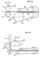
- Another advantageous embodiment of the invention exists 12 therein, which is the carrier web 6 opposite Side of the wave track also with another material track 25 to connect.
- the material web 25 is also used as a cover web designated.
- This track can be used for this purpose, for example by means of a roller of larger diameter 26 and one Belt system 27 are supplied, by means of a Application device 15 applied in strip form adhesive becomes.
- a second Belt system 28 and a pressing device 30, which the Contact pressure evenly distributed, the bond with the Wave track 1 take place, the support 29 the Counteracts pressure.
- the curvature of the roller 31 is chosen so that the wave path is only slightly elastically deformed and after Leave the roller its original cross-section again occupies.
- glue on the shaft tips in a region of the roller 31 be applied.
- a subsequent pressing section with controlled contact pressure as described under Fig. 12 the connection is strengthened.
- the invention further relates to an absorbent Article suitable for the absorption of body fluids is.
- Such articles are articles for example Feminine hygiene, such as sanitary napkins, and diapers, Incontinence pads or the like.
- the aforementioned hygiene articles are in a wide variety Embodiments known. This is a back liquid-permeable cover layer, a front, liquid-permeable cover layer and a between them absorbent body arranged in two layers together.
- the back cover layer is usually made of a thin Polyethylene film formed.
- Liquid-permeable cover layers mostly become nonwovens used.
- the use of perforated foils is also known.
- the absorbent body usually consists of cellulose flakes or an air-laid fiber web - a so-called air-laid material.
- the inventive folding of the front Cover layer is a surface effect that most likely can be described with the expression "pleating".
- the folds simultaneously create longitudinal channels on the Surface of the hygiene article to improve the Liquid distribution in the longitudinal direction and barriers against created a liquid spread in the transverse direction. This significantly improves the leak-proofness of the hygiene article.
- the folds in considerable areas of the Cover layer a distance between these and the one below located absorbent body, the suction or Penetration of body fluid into the absorbent and at the same time improves the rewetting properties. Also the visual impression after exposure e.g. by Menstrual fluid, improved since the sublime Do not fold areas with the liquid-soaked absorbent stay in contact. Last but not least, the The pliability of the folds is the softness of the body facing surface of the hygiene article affects what the Comfort and natural grip improved.
- Suitable materials for the pleated absorbent body are hydrophilic nonwovens, such as hydrophilic carded nonwovens or hydrophilic spunbonded nonwovens with basis weights of 6 to 80 g / m 2 , in particular 10 to 30 g / m 2 , air-laid fiber webs and laminates.
- Hydrophobic nonwovens such as hydrophobic carded nonwovens and hydrophobic spunbonded nonwovens, can be used for the pleated cover layer.
- the basis weight of corresponding materials is again preferably in the range from 5 6 to 30 80 g / m 2 , in particular 10 to 20 g / m 2 .
- the absorbent body facing foot areas of the folds on the absorbent or one between this and the front cover layer arranged carrier layer are fixed, the folds are so stabilized that the positive they evoked Effects even after storage in the pressed state and over a longer wearing time is preserved.
- the foot areas of the folds can be glued (Adhesive strips) or welding on the absorbent or the carrier layer on a width (foot width F) of preferably 0.2 to 10 mm can be fixed.
- the carrier layer can have the functional properties of the Wrinkles with regard to fluid transmission and Improve rewetting.
- the foot areas of two adjacent folds can be made with one mutual distance (A) of 1 to 20 mm and the Standing height (II) of the folds in the unloaded state can also be 1 to 20 mm.
- multiple folds distributed over the entire width of the absorbent surface be provided. This will result in maximum product improvement achieved. 5 to 25 folds across the entire width have been found to be proven particularly favorable. Finally, several preferably 2 to 10 folds each in a section of the Absorbent surface limited, edge and / or center Strips may be provided.
- the different embodiments of the sanitary napkin shown a basic structure that corresponds in essential points on.
- the back, liquid impermeable Cover layer provided a laundry protection film 101, which as the Absorbent 102 formed in the area of cellulose flock cushions its back 103 - that of the wearer in the created Condition of the sanitary napkin facing away from the body - is subject.
- the laundry protection film 101 also engages with its longitudinal edges 104 around the side edge 105 of the absorbent body 102.
- the carrier layer 107 also engages with its longitudinal edges 108 around the side edge 105 of the Suction body 102 around and overlaps with the longitudinal edges 104 of the Laundry protection film 101. These two are in the overlap area Parts glued together in the usual way.
- Liquid-permeable cover layer 109 is provided, which is still in is provided with folds 110 to be explained in more detail.
- Sanitary napkin is a so-called "Full wrapping bandage", in which the cover layer 109, the for example is made of a polypropylene carded fleece, around the absorbent body 102, the carrier layer 107 and the cover layer 109 struck on the back 103 and in the middle by a Adhesive connection 111 fixed.
- a back Cover layer 115 are formed.
- the cover layer 115 can be made Nonwoven fabric can be formed, as is particularly the case in the 16 embodiment shown is the case where its own Laundry protection film 101 is provided.
- the top layer can, however even with the laundry protection film 101 omitted liquid impermeable material, for example Polyethylene film to be made to the Take over laundry protection function.
- the folds 110 are covered by a suitable fold layer in the Bandage making machine applied so that the foot areas 116 with a distance A in the transverse direction of the napkin on the Carrier layer 107 come to rest, which is in the range between 1 and 20 mm. Has proven to be particularly practical Distance range from 3 to 5 mm highlighted.
- the foot areas 116 by longitudinal adhesive strips 117, the are formed, for example, from a spray adhesive on which Carrier layer 107 fixed. Between each other The folds 110 protrude upward from foot regions 116, one of which Standing height H in the range from 1 to 20 mm is conceivable. As Values for the have been particularly practical Standoff height highlighted in the range between 3 and 5 mm lie.
- foot width F can be between 0.2 and 10 mm, taking care that the Foot width F is a maximum of half the distance A. at have a distance A and a headroom H of 3 to 5 mm proven foot widths from 0.5 to 1 mm.
- a sanitary napkin outlined in FIG. 18 is in addition to the folds 110 in the two edges Stripe 118 symmetrical to the central plane L another Fold configuration with three folds 110 provided crease-free strips 120 between the central folds 110 and the edge folds 110 remain.
- the bandage according to the invention in each case from suitable materials the available offer according to the usual criteria to choose for the construction of such hygiene articles and suitable construction measures must be taken.
- the adhesive strips 117 should be designed to cover the surface the carrier layer 107 against one another only to the smallest possible extent Seal the liquid passage so that the absorbent The surface of the bandage remains as large as possible. So it can be a Spray glue or melt-blown glue in thin threads be used. Also welding or sealing through Laser, ultrasound or heat is conceivable.
- FIG. 19 and 20 are finally embodiments of the illustrated absorbent article according to the invention which the absorbent body 205 has a pleated shape.
- the Articles shown in the figures mentioned contain about it also a pleated cover layer 203, which in Connection points 202 with an outer cover layer 201 are connected (Fig. 19).
- the one shown in Fig. 19 Embodiment also shows one liquid-impermeable cover layer 204, which in the Technical jargon is also called "polybaffle".
- the absorbent body which contains at least one corrugated web,
- card fleece and Spunbonded fabric for example also an air-laid fiber web, Laminates or the material specified in more detail below Coform included.
- Pulp-synthetic fiber mixtures can easily absorb up to 25 g / g of liquid.
- the absorbent additionally contain a superabsorbent. These superabsorbents have one Liquid absorption capacity of about 1 to 500 g / g physiological saline. For the body's own fluid the absorption capacity is about 1 g / g to 80 g / g.
- Suitable components of the absorbent body are materials made of carded nonwoven, spunbonded nonwoven, web material made of cellulose / synthetic fiber mixture (coform), a solidified air-laid cellulose web (airlaid material), or an air-laid cellulose / synthetic fiber mixture web (thermo-fixed airlaid material). Also suitable are prism and coform materials, absorbent sheets of air-laid cellulose, cellulose / synthetic fiber mixtures or synthetic fiber nonwovens with a basis weight of approximately 12 to approximately 400 g / m 2 , preferably 50 to 150 g / m 2 , in particular 100 g / m 2 and / or thicknesses of 0.1 to 3 mm, preferably 0.2 to 2 mm, in particular 1 mm.
- the body-side cover layer should preferably be hydrophilic Have properties. Possible additional transport layers and / or materials between the body-side cover layer and Absorbent bodies can be both hydrophilic and hydrophobic.
- the pleated cover layer 203 also by a non-pleated one Layer can be replaced. Even if only at least a part of the absorbent body is pleated at one hygiene article according to the invention the side Leakproofness increased and a better longitudinal distribution of the absorbed liquid reached. Furthermore is course that both the liquid permeable Cover layer as well as the liquid-impermeable cover layer for an absorbent article with an at least partially corrugated absorbent body from those described in more detail above Materials can be built.
- the wave height H 1 in the center of the absorbent article is preferably a maximum of ten times the value of the wave height H 2 in edge areas of the article.
- the longitudinally corrugated sheets produced according to the invention were made on ultra-thin absorbent bodies applied.
- Table 2 shows the performance data corresponding absorbent article summarized.
- the one-sided or two-sided treatment of the prism material by means of an arivage process results in better liquid absorption and faster penetration of the liquid, especially if the material is hydrophilized.
Landscapes
- Health & Medical Sciences (AREA)
- Epidemiology (AREA)
- Engineering & Computer Science (AREA)
- Biomedical Technology (AREA)
- Heart & Thoracic Surgery (AREA)
- Vascular Medicine (AREA)
- Life Sciences & Earth Sciences (AREA)
- Animal Behavior & Ethology (AREA)
- General Health & Medical Sciences (AREA)
- Public Health (AREA)
- Veterinary Medicine (AREA)
- Physics & Mathematics (AREA)
- Fluid Mechanics (AREA)
- Dermatology (AREA)
- Chemical & Material Sciences (AREA)
- Composite Materials (AREA)
- Mechanical Engineering (AREA)
- Absorbent Articles And Supports Therefor (AREA)
- Orthopedics, Nursing, And Contraception (AREA)
- Laminated Bodies (AREA)
- Reinforced Plastic Materials (AREA)
- Solid-Sorbent Or Filter-Aiding Compositions (AREA)
- Wrappers (AREA)
- Electric Propulsion And Braking For Vehicles (AREA)
- Making Paper Articles (AREA)
- Machines For Manufacturing Corrugated Board In Mechanical Paper-Making Processes (AREA)
- Shaping Of Tube Ends By Bending Or Straightening (AREA)
- Treatments For Attaching Organic Compounds To Fibrous Goods (AREA)
- Paper (AREA)
Description
- Fig. 1
- eine perspektivische, teilweise aufgeschnittene Ansicht einer Maschine zur Herstellung einer gewellten Bahn aus sehr elastischem Material, die mit einer Trägerbahn verbunden wird,
- Fig. 2
- eine perspektivische Draufsicht auf die gewellte Bahn, die zugleich der Form des Führungsbetts in einer bevorzugten Ausführung darstellt,
- Fig. 3
- eine perspektivische Darstellung einer alternativen, in der Mitte beginnenden Wellenausbildung,
- Fig. 4
- eine perspektivische Draufsicht auf eine Bahn bzw. ein Führungsbett mit nur teilweiser Wellenbildung,
- Fig. 5
- einen Querschnitt durch drei Sektionen des Führungsbetts am Anfang, in der Mitte und am Ende mit einer schematischen Darstellung der eingezogenen Bahn,
- Fig. 6
- verschiedene theoretische Ausformmöglichkeiten der gewellten Bahn mit unterschiedlichen Einzugsfaktoren,
- Fig. 7
- materialtechnische Betrachtungen für vorzugsweise zu verarbeitende Bahnen,
- Fig. 8
- eine Seitenansicht des Führungsbettendes mit einer Verbindungseinrichtung sowie die Fixierung einer Andruckmöglichkeit der Niederhalter mittels Pneumatikzylinder und Kniehebel,
- Fig. 9
- eine teilweise aufgeschnittene perspektivische Ansicht des Führungsbetts und der Niederhalter, auf welche hier durch getrennt ansteuerbare Elektromagnete jeweils abschnittsweise veränderliche Kräfte aufgebracht werden können,
- Fig. 10
- eine Ansicht der beiden Walzen der Verbindungsstation mit den in die gewellte Walze eingreifenden Niederhaltern und streifenförmigem Leimauftrag,
- Fig. 11
- eine schematische Darstellung von nachgeschalteten Prägewalzen, welche die gewellte Bahn an den Wellenspitzen zur Fixierung durch Pressen verformen,
- Fig. 12
- eine schematische Darstellung der Aufbringung einer zweiten Bahn mit der anschließenden Preßstation zur Fixierung der Klebeverbindung,
- Fig. 13
- eine schematische Darstellung einer weiteren bevorzugten Ausführung zur Verklebung der zweiten Bahn, und
- Fig. 14 bis 21
- schematische Darstellungen von absorbierenden Artikeln gemäß der Erfindung.
| Materialien | Dimensionen | Kardenvlies | Spinnvlies | Laminat Kardenvlies/ Lochfolie | Laminat Spunbond/ Lochfolie |
| Flächengewicht | g/m2 | 18 | 16 | 43 | 42 |
| Dicke | mm | 0,18 | 0,13 | 0,92 | 0,50 |
| Festigkeiten, trocken | |||||
| längs | N/50 mm | 40 | 30 | 55 | 13 |
| quer | N/50 mm | 18 | 20 | 19 | 6 |
| Dehnung, trocken | |||||
| längs | % | 50 | 50 | 35 | 34 |
| quer | % | 90 | 60 | 150 | 78 |
| Reibung, trocken | |||||
| Innen(Folien)-seite | µD | 0,65 | 0,33 | 0,41 | 0,30 |
| Außen(Vlies)-seite | µD | 0,65 | 0,33 | 0,41 | 0,93 |
- Prism:
- Spezial-Spinnvlies mit hohem Volumen, einseitig oder zweiseitig behandelt; Flächengewichte von etwa 12 bis etwa 80 g/m2. Prism 0,5 entspricht einem Flächengewicht von etwa 17 g/m2. Prism 1,0 entspricht einem Flächengewicht von etwa 35 g/m2.
- Ekotec:
- high loft Kardenvlies, welches mittels heißer Luft getrocknet ist (hot through air dried), hohes Volumen; Flächengewichte von etwa 12 bis etwa 70 g/m2.
- Coform:
- Zellstoff/Polypropylenmischung, Zellstoff zerfasert mit gesponnenen PP-Fasern vergefestigt; Flächengewichte etwa 40 bis etwa 400 g/m2.

Claims (53)
- Vorrichtung zur kontinuierlichen Erzeugung einer zumindest in Teilbereichen gewellten Bahn (1) aus dünnem, blattförmigem, und zumindest in Querrichtung zur Bahn dehnbarem Material, enthaltendein Führungsbett (2), welches einen glatten Oberflächenbereich aufweist, an dem das Material anliegend vorbeiführbar ist, und welches in Bewegungsrichtung des Materials parallel oder schräg zueinander verlaufende Rillen aufweist, wobei jede Rille ausgehend von einer bezüglich der Bewegungsrichtung der Materialbahn stromaufwärt gelegenen Stelle in Richtung auf ein Austrittsende (4) des Führungsbetts (2) zunehmend tiefer in die Oberfläche des Führungsbetts (2) eingeschnitten ist und wobei die Oberseite des Führungsbetts (2) zumindest in dem Bereich, in dem die Rillen verlaufen, im wesentlichen eben ausgebildet ist,Niederhalter (5), welche den Rillen des Führungsbetts (2) gegenüberliegend derart angeordnet sind, daß sie die zwischen der Oberfläche des Führungsbetts (2) und den Niederhaltern (5) geführte Bahn zur Erzielung von Wellen in der Bahn in die Rillen des Führungsbetts (2) drängen,
sowieein am Austrittsende (4) des Führungsbetts (2) angeordnetes Mittel, welches eine Rückbildung der ausgebildeten Wellen im wesentlichen verhindert. - Vorrichtung nach Anspruch 1, wobei das am Austrittsende (4) des Führungsbetts (2) angeordnete Mittel, welches die Rückbildung der ausgebildeten Wellen verhindert, unmittelbar an das Austrittsende des Führungsbetts anschließt.
- Vorrichtung nach Anspruch 1 oder Anspruch 2, wobei die Niederhalter (5) eine Vorspannung aufweisen.
- Vorrichtung nach einem der vorhergehenden Ansprüche, wobei die Niedehalter (5) ein freies, nicht geführtes oder gelagertes Ende aufweisen, welches in die Rillen eintauchbar ist.
- Vorrichtung nach einem der vorhergehenden Ansprüche, wobei die Niederhalter (5) an dem Eintrittsende (3) des Führungsbetts (2) und/oder dem Austrittsende (4) des Führungsbetts (2) zugewandten Ende in senkrecht zum Führungsbett verlaufender Richtung verschiebbar gelagert sind.
- Vorrichtung nach einem der vorhergehenden Ansprüche, wobei die Niederhalter (5) in zumindest einer senkrecht zum Führungsbett (2) verlaufenden Führungsfläche geführt sind.
- Vorrichtung nach einem der vorstehenden Ansprüche, wobei die freien Enden der Niedehalter (5) im wesentlichen parallel zueinander abgebogen oder mit entsprechenden Ansätzen versehen sind, die in Bohrungen von zumindest einem endseitig gelegenen Führungselement aufnehmbar sind.
- Vorrichtung nach einem der vorhergehenden Ansprüche, wobei alle Niederhalter bezüglich der Laufrichtung der Bahn vor bzw. nach dem Oberflächenbereich aufnehmbar sind.
- Vorrichtung nach einem der vorhergehenden Ansprüche, dadurch gekennzeichnet, daß die Niederhalter (5) einen ferromagnetischen Werkstoff, vorzugsweise Stahl, enthalten.
- Vorrichtung nach einem der vorhergehenden Ansprüche, wobei die Niederhalter (5) einen runden Querschnitt aufweisen.
- Vorrichtung nach Anspruch 10, wobei die Niederhalter (5) einen Durchmesser von 0,1 bis 5 mm, vorzugsweise 1 bis 3 mm, insbesondere 2 mm, aufweisen.
- Vorrichtung nach einem der vorhergehenden Ansprüche, wobei die Rillen einen Abstand von 1 bis 10 mm, vorzugsweise 2 bis 4 mm, aufweisen.
- Vorrichtung nach einem der vorhergehenden Ansprüche, wobei diese Mittel aufweist, welche auf die Niederhalter einwirken, so daß diese mit einer vorgegebenen Kraft die Bahn (1) gegen das Führungsbett (2) drücken.
- Vorrichtung nach Anspruch 13, wobei das Mittel so angeordnet ist, daß eine Krafteinwirkung auf die Niederhalter in einem Bereich erfolgt, welcher zwischen den Enden der Niederhalter (5) liegt.
- Vorrichtung nach einem der Ansprüche 13 oder 14, wobei die Mittel zumindest ein Federelement (11), zumindest ein Gewicht, Druckluft, Vakuum und/oder zumindest einen Magneten enthalten.
- Vorrichtung nach Anspruch 15, wobei der zumindest eine Magnet ein Permanentmagnet ist.
- Vorrichtung nach Anspruch 15 oder 16, wobei der zumindest eine Magnet ein Elektromagnet (22) ist.
- Vorrichtung nach einem der Ansprüche 15 bis 17, wobei der Magnet auf der den Niederhaltern gegenüberliegenden Seite des Führungsbetts (2) angeordnet ist.
- Vorrichtung nach einem der Ansprüche 13 bis 18, wobei das Mittel eine Druckplatte (10) ist.
- Vorrichtung nach Anspruch 19, wobei die Druckplatte aus Kunststoff ist.
- Vorrichtung nach einem der vorhergehenden Ansprüche, wobei die Niederhalter (5) mit einer Kraft von 0,01 bis 0,1 Ncm-1, vorzugsweise 0,02 bis 0,08 Ncm-1, insbesondere 0,04 bis 0,06 Ncm-1, belastet werden.
- Vorrichtung nach einem der vorhergehenden Ansprüche, wobei das am Austrittsende (4) des Führungsbetts (2) angeordnete Mittel, welches eine Rückbildung der ausgebildeten Wellen verhindert, eine Einrichtung ist, um die gewellte Bahn mit zumindest einem bahnförmigsn Material (6) zu verbinden.
- Vorrichtung nach Anspruch 22, wobei die Wellen der gebildeten gewellten Bahn im Bereich der Maxima und/oder Minima der Wellen mit dem bahnförmigen Material fixiert werden.
- Vorrichtung nach Anspruch 19, dadurch gekennzeichnet, daß die Einrichtung zur Verbindung der gewellten Bahn mit einer Trägerbahn Walzen (12,13) aufweist, und daß die Niederhalter (5) in die Ausnehmungen einer profillierten Walze reichen.
- Vorrichtung nach einem der Ansprüche 22 bis 24, wobei die Einrichtung zur Verbindung der gewellten Bahn (1) mit einem bahnförmigen Material (6) Mittel (15) aufweist, um auf das bahnförmige Material (6) und/oder die gewellte Bahn (1) ein Haftmittel aufzubringen.
- Vorrichtung nach einem der vorhergehenden Ansprüche, wobei das Mittel, welches eine Rückbildung der ausgebildeten Wellen verhindert, eine Einrichtung ist, welche die gebildete gewellte Bahn durch thermische und/oder chemische und/oder physikalische Einwirkung in ihrer Form fixiert.
- Vorrichtung nach einem der vorhergehenden Ansprüche, wobei das Führungsbett (2) so ausgebildet ist, daß die parallel zueinander verlaufenden Rillen im Mittelteil (17) des Führungsbetts (2) und weiter an den Randbereichen liegende Rillen stromabwärts zur Laufrichtung der Bahn jeweils trichterförmig beginnen.
- Vorrichtung nach einem der vorhergehenden Ansprüche, wobei das Führungsbett (2) so ausgebildet ist, daß nicht die gesamte Breite mit Rillen versehen ist, sondern im Mittelteil und/oder in Randbereichen (19) des Führungsbetts (2) keine Rillen vorgesehen sind.
- Vorrichtung nach einem der vorhergehenden Ansprüche, wobei die Einrichtung weiterhin eine Vorrichtung mit kämmenden Walzen (23,24) zur Prägung der erzeugten gewellten Bahn (1) aufweist, wobei die Einrichtung mit kämmenden Walzen dem Führungsbett (2) nachgeschaltet ist.
- Verfahren zur kontinuierlichen Herstellung einer zumindest in Teilbereichen gewellten Bahn aus dünnem, blattförmigem und zumindest in Querrichtung zur Bahn dehnbarem Material, insbesondere mittels einer Vorrichtung gemäß einem der vorstehenden Ansprüche, gekennzeichnet durch folgende Schritte:Hindurchführen des Materials durch zumindest eine Vorrichtung, welche gegenseitig in Wirkverbindung stehende formgebende Elemente enthalten, undanschließendes Fixieren zumindest eines Bereichs der gewellten Bahn in einer Weise, daß zumindest der Abstand zweier benachbarter Wellen konstant gehalten wird.
- Verfahren nach Anspruch 30, wobei das Material zwischen einem Führungsbett, das eine glatte Oberfläche und in Bewegungsrichtung des Materials parallel oder schräg zueinander verlaufende Rillen aufweist, wobei jede Rille ausgehend von einer bezüglich der Bewegungsrichtung des Materials stromaufwärts gelegenen Stelle in Richtung auf ein Austrittsende des Führungsbetts zunehmend tiefer in die Oberfläche des Führungsbetts eingeschnitten ist, und die Oberseite des Führungsbetts in dem Bereich, in dem die Rillen verlaufen, im wesentlichen eben verläuft, und Niederhaltern, welche den Rillen der Führungsbahn (2) gegenüberliegend derart angeordnet sind, daß sie eine zwischen der Oberfläche des Führungshaltersbetts (2) und den Niederhaltern (5) geführte Bahn zur Erzielung von Wellen in der Bahn in die Rillen des Führungsbetts (2) drängen, geführt wird.
- Verfahren nach einem der Ansprüche 30 oder 31, wobei die Niederhalter mit einer vorgegebenen Kraft gegen die Bahn und das Führungsbett gedrückt wird.
- Verfahren nach Anspruch 32, wobei die vorgegebene Kraft 0,01 bis 0,1 Ncm-1, vorzugsweise 0,02 bis 0,08 Ncm-1, insbesondere 0,04 bis 0,06 Ncm-1, beträgt.
- Verfahren nach Anspruch 32 oder 33, wobei die vorgegebene Kraft längs und/oder quer zur Laufrichtung der Bahn veränderlich eingestellt wird.
- Verfahren nach einem der Ansprüche 32 bis 34, wobei die vorgebene Kraft mittels zumindest eines Federelement, zumindest eines Gewichts, Druckluft, Vakuum und/oder zumindest eines Magnets erzeugt wird.
- Verfahren nach Anspruch 35, dadurch gekennzeichnet, daß der Magnet ein Permanentmagnet ist.
- Verfahren nach einem der Ansprüche 35, wobei der Magnet ein Elektromagnet ist.
- Verfahren nach einem der Ansprüche 30 bis 37, wobei die Fixierung der gewellten Bahn mittels Verbinden zumindest mit einem bahnförmigen Material erfolgt.
- Verfahren nach Anspruch 38, wobei die längsgewellte Bahn durch ein Haftmittel mit dem bahnförmigen Material verbunden wird, wobei das Haftmittel vorzugsweise auf Wellenkämme bzw. Maxima der Wellen der gewellten Bahn aufgebracht wird oder auf die zulaufende Bahn an der der Maxima der Wellen gegenüberliegenden Orten aufgebracht wird.
- Verfahren nach Anspruch 38 oder 39, wobei die gewellte Bahn durch thermische Einwirkung mit dem bahnförmigen Material verbunden wird.
- Verfahren nach einem der Ansprüche 38 bis 40, wobei die gewellte Bahn durch Ultraschallschweißung mit dem bahnförmigen Material verbunden wird.
- Verfahren nach einem der Ansprüche 38 bis 41, wobei die Anpreßkraft für die Verbindung der gewellten Bahn mit dem bahnförmigen Material über eine Strecke derart aufgebracht wird, daß der auf jede Welle wirkende Druck geringer ist als ein Druck, welcher die Welle deformiert.
- Verfahren nach einem der Ansprüche 30 bis 42, wobei die Fixierung der gewellten Bahn durch thermische und/oder phsikalisch-chemische Einwirkung erfolgt.
- Verfahren nach einem der Ansprüche 30 bis 42, wobei die Wellenbildung in Laufrichtung der Bahn im Mittelteil der Bahn beginnt und weiter an den Seiten liegende Wellen nacheinander ausgeformt werden.
- Verfahren nach einem der Ansprüche 30 bis 44, wobei nicht die gesamte Bahn in Wellen gelegt wird, sondern in der Mitte und/oder am Rand ein Teil der Bahn unverformt bleibt.
- Verfahren nach einem der Ansprüche 30 bis 45, wobei die erzeugte gewellte Bahn mittels kämmender Walzen nachgeprägt wird.
- Verfahren nach einem der Ansprüche 30 bis 46, wobei die Materialbahn in Querrichtung um mindestens 10 % verformbar ist.
- Verfahren nach Anspruch 47, wobei die Materialbahn zumindest in Querrichtung elastisch ist.
- Verfahren nach einem der Ansprüche 30 bis 47, wobei als Materialbahn ein Kardenvlies, ein Spinnvlies, mehrlagige Laminate aus gelochten Folien und Spinnvliesen oder mehrlagige Laminate aus gelochten Folien und Kardenvliesen eingesetzt wird.
- Verfahren nach Anspruch 49, wobei das Spinnvlies ein Flächengewicht zwischen 6 und 80 g/m2, vorzugsweise 10 bis 30 g/m2, insbesondere 16 g/m2, und/oder eine Dicke von 0,05 bis 1,5 mm, vorzugsweise 0,1 bis 0,5 mm, besonders bevorzugt 0,1 bis 0,2 mm, insbesondere 0,13 mm, aufweist und das Kardenvlies ein Flächengewicht zwischen 6 und 80 g/m2, vorzugsweise 10 bis 30 g/m2, insbesondere 18 g/m2 und/oder eine Dicke von 0,05 bis 1,5 mm, vorzugsweise 0,1 bis 0,5 mm, besonders bevorzugt 0,1 bis 0,2 mm, insbesondere 0,18 mm, aufweist.
- Verfahren nach Anspruch 49, wobei die mehrlagigen Laminate ein Flächengewicht von 20 bis 200 g/m2, vorzugsweise 30 bis 100 g/m2, insbesondere 42 g/m2 und/oder eine Dicke von 0,15 bis 4,0 mm, vorzugsweise 0,3 bis 1,5 mm, insbesondere 0,5 mm aufweisen.
- Verfahren nach einem der Ansprüche 38 bis 52, dadurch gekennzeichnet, daß als bahnförmiges Material ein Spinnvlies mit hohem Volumen und/oder ein Kardenvlies mit hohem Volumen eingesetzt wird.
- Absorbierender Artikel hergestellt durch das Verfahren nach einem der Ansprüche 30 bis 52, miteiner flüssigkeitsundurchlässigen Abdecklage,einer flüssigkeitsdurchlässigen Abdecklage, undeinem zwischen flüssigkeitsundurchlässiger Abdecklage und flüssigkeitsdurchlässiger Abdecklage angeordneten Saugkörper,wobei die flüssigkeitsdurchlässige Abdecklage und/oder der Saugkörper eine gewellte Bahn enthalten, welche hergestellt wurde.
Priority Applications (1)
| Application Number | Priority Date | Filing Date | Title |
|---|---|---|---|
| EP01115950A EP1151734A3 (de) | 1994-06-30 | 1995-06-30 | Absorbierender Artikel |
Applications Claiming Priority (3)
| Application Number | Priority Date | Filing Date | Title |
|---|---|---|---|
| DE4422956A DE4422956A1 (de) | 1994-06-30 | 1994-06-30 | Absorbierender Hygieneartikel zur Aufnahme von Körperflüssigkeiten |
| DE4422956 | 1994-06-30 | ||
| PCT/EP1995/002550 WO1996000625A2 (de) | 1994-06-30 | 1995-06-30 | Vorrichtung und verfahren zur erzeugung einer gewellten bahn sowie absorbierendes produkt enthaltend eine gewellte bahn |
Related Child Applications (1)
| Application Number | Title | Priority Date | Filing Date |
|---|---|---|---|
| EP01115950A Division EP1151734A3 (de) | 1994-06-30 | 1995-06-30 | Absorbierender Artikel |
Publications (2)
| Publication Number | Publication Date |
|---|---|
| EP0767732A2 EP0767732A2 (de) | 1997-04-16 |
| EP0767732B1 true EP0767732B1 (de) | 2002-12-04 |
Family
ID=6521935
Family Applications (3)
| Application Number | Title | Priority Date | Filing Date |
|---|---|---|---|
| EP95925757A Expired - Lifetime EP0767649B1 (de) | 1994-06-30 | 1995-06-24 | Wellenformige oberschicht für absorbiernde artikel |
| EP95925799A Expired - Lifetime EP0767732B1 (de) | 1994-06-30 | 1995-06-30 | Vorrichtung und verfahren zur erzeugung einer gewellten bahn sowie absorbierendes produkt enthaltend eine gewellte bahn |
| EP01115950A Withdrawn EP1151734A3 (de) | 1994-06-30 | 1995-06-30 | Absorbierender Artikel |
Family Applications Before (1)
| Application Number | Title | Priority Date | Filing Date |
|---|---|---|---|
| EP95925757A Expired - Lifetime EP0767649B1 (de) | 1994-06-30 | 1995-06-24 | Wellenformige oberschicht für absorbiernde artikel |
Family Applications After (1)
| Application Number | Title | Priority Date | Filing Date |
|---|---|---|---|
| EP01115950A Withdrawn EP1151734A3 (de) | 1994-06-30 | 1995-06-30 | Absorbierender Artikel |
Country Status (25)
| Country | Link |
|---|---|
| US (1) | US6171682B1 (de) |
| EP (3) | EP0767649B1 (de) |
| JP (2) | JP3998707B2 (de) |
| KR (2) | KR970703849A (de) |
| CN (2) | CN1095652C (de) |
| AT (1) | ATE183073T1 (de) |
| AU (2) | AU2977795A (de) |
| BR (2) | BR9508129A (de) |
| CA (2) | CA2192556C (de) |
| CZ (2) | CZ286196B6 (de) |
| DE (3) | DE4422956A1 (de) |
| DK (1) | DK0767649T3 (de) |
| ES (1) | ES2134485T3 (de) |
| FI (1) | FI965211L (de) |
| GR (1) | GR3031067T3 (de) |
| HU (1) | HU217247B (de) |
| MX (1) | MX9606414A (de) |
| MY (1) | MY113467A (de) |
| NO (1) | NO307544B1 (de) |
| NZ (1) | NZ289820A (de) |
| PE (1) | PE40596A1 (de) |
| TR (1) | TR199500774A2 (de) |
| TW (1) | TW350886B (de) |
| WO (2) | WO1996000545A1 (de) |
| ZA (1) | ZA955324B (de) |
Families Citing this family (92)
| Publication number | Priority date | Publication date | Assignee | Title |
|---|---|---|---|---|
| US6548147B1 (en) | 1995-06-30 | 2003-04-15 | Kimberly-Clark Worldwide, Inc. | Apparatus and process for producing a corrugated web and an absorbent article comprising a corrugated web |
| DE4422956A1 (de) | 1994-06-30 | 1996-01-04 | Schickedanz Ver Papierwerk | Absorbierender Hygieneartikel zur Aufnahme von Körperflüssigkeiten |
| JP3224481B2 (ja) * | 1994-10-26 | 2001-10-29 | ユニ・チャーム株式会社 | 生理用ナプキン |
| DE19609462A1 (de) * | 1996-03-11 | 1997-09-18 | Kimberly Clark Gmbh | Absorbierender Artikel sowie Verfahren zur gerichteten Abführung von lokalisiert austretenden Fluiden |
| SE507050C2 (sv) * | 1996-04-30 | 1998-03-23 | Moelnlycke Ab | Höljesskikt för absorberande artiklar uppvisande vågform och innefattande vinkelrätt mot vågorna löpande rader av genomgående öppningar samt förfarande för tillverkning av skiktet |
| US6319239B1 (en) | 1996-12-20 | 2001-11-20 | The Procter & Gamble Company | Absorbent article having improved integrity and acquisition |
| DE69626051T2 (de) * | 1996-12-20 | 2003-11-20 | The Procter & Gamble Company, Cincinnati | Absorbierende artikel mit verbesserter integrität und flüssigkeitsaufnahme |
| US6648869B1 (en) * | 1996-12-30 | 2003-11-18 | Kimberly-Clark Worldwide, Inc. | Vertically pleated diaper liner |
| TR200003618T2 (tr) * | 1998-04-02 | 2001-06-21 | The Procter & Gamble Company | Çok bölgeli parça |
| US6537936B1 (en) | 1998-04-02 | 2003-03-25 | The Procter & Gamble Company | Multiple zone member |
| EP0953323A1 (de) * | 1998-05-02 | 1999-11-03 | The Procter & Gamble Company | Absorbierender Wegwerfartikel mit verbesserter, oberer Lage |
| US6545197B1 (en) | 1998-05-02 | 2003-04-08 | The Procter & Gamble Company | Disposable absorbent article having an improved topsheet |
| JPH11342154A (ja) * | 1998-06-03 | 1999-12-14 | Uni Charm Corp | 体液吸収性物品 |
| EP0976375A1 (de) * | 1998-07-29 | 2000-02-02 | The Procter & Gamble Company | Absorbierender Wegwerfartikel mit Fäkalienmanagementschicht |
| JP2000135239A (ja) * | 1998-10-30 | 2000-05-16 | Uni Charm Corp | 使い捨ての体液吸収性着用物品 |
| KR100548233B1 (ko) * | 1998-12-15 | 2006-05-09 | 엘지전자 주식회사 | 네트워크를 이용한 양방향 방송 시스템 |
| JP3616728B2 (ja) * | 1999-01-19 | 2005-02-02 | ユニ・チャーム株式会社 | 体液吸収性物品 |
| JP3639450B2 (ja) * | 1999-01-20 | 2005-04-20 | ユニ・チャーム株式会社 | 使い捨ての体液処理用吸収性物品 |
| JP2000271170A (ja) * | 1999-03-25 | 2000-10-03 | Uni Charm Corp | 表面構造体を有する吸収性物品 |
| AR027842A1 (es) * | 1999-08-23 | 2003-04-16 | Kimberly Clark Co | Un articulo absorbente el cual mantiene o mejora la salud de la piel |
| US6605172B1 (en) * | 1999-09-30 | 2003-08-12 | The Procter & Gamble Company | Method of making a breathable and liquid impermeable web |
| JP3748743B2 (ja) * | 1999-10-04 | 2006-02-22 | ユニ・チャーム株式会社 | 吸収性物品およびその製造方法 |
| US6692603B1 (en) * | 1999-10-14 | 2004-02-17 | Kimberly-Clark Worldwide, Inc. | Method of making molded cellulosic webs for use in absorbent articles |
| JP3751182B2 (ja) * | 2000-03-31 | 2006-03-01 | ユニ・チャーム株式会社 | 可撓性の複合シート |
| JP3875007B2 (ja) * | 2000-09-01 | 2007-01-31 | ユニ・チャーム株式会社 | 連続フィラメントを有する表面層を用いた吸収性物品およびその製造方法 |
| JP3617637B2 (ja) * | 2000-09-22 | 2005-02-09 | 花王株式会社 | 吸収性物品用の表面シート |
| EP1190690B9 (de) * | 2000-09-22 | 2012-08-01 | Kao Corporation | Obere Schicht für absorbierenden Artikel |
| JP4459007B2 (ja) * | 2000-09-22 | 2010-04-28 | 花王株式会社 | 吸収性物品用の表面シート |
| SE517826C2 (sv) * | 2000-10-02 | 2002-07-23 | Sca Hygiene Prod Ab | Absorberande artikel med distansskapande medel i barriärelastiken som skapar tvärgående vätskeledande kanaler |
| US7147628B2 (en) | 2000-10-02 | 2006-12-12 | Sca Hygiene Products Ab | Absorbent article with improved liquid-handling ability |
| US6572599B2 (en) | 2000-10-02 | 2003-06-03 | Sca Hygiene Products Ab | Absorbent article with improved liquid-handling ability |
| SE517857C2 (sv) * | 2000-10-02 | 2002-07-23 | Sca Hygiene Prod Ab | Absorberande artikel med läckagebarriärer innehållande distanselement som skapar stabila tvärgående kanaler |
| US6488670B1 (en) * | 2000-10-27 | 2002-12-03 | Kimberly-Clark Worldwide, Inc. | Corrugated absorbent system for hygienic products |
| US6946413B2 (en) * | 2000-12-29 | 2005-09-20 | Kimberly-Clark Worldwide, Inc. | Composite material with cloth-like feel |
| US20020132543A1 (en) * | 2001-01-03 | 2002-09-19 | Baer David J. | Stretchable composite sheet for adding softness and texture |
| DE10103627B4 (de) * | 2001-01-27 | 2007-11-15 | Sandler Ag | Vliesstoff mit Struktur |
| US20020165517A1 (en) * | 2001-03-01 | 2002-11-07 | Kimberly-Clark Worldwide, Inc. | Prefastened diaper/pant for infants with improved fit range |
| JP4167404B2 (ja) * | 2001-04-18 | 2008-10-15 | 大王製紙株式会社 | 生理用ナプキン |
| US7427434B2 (en) * | 2001-04-20 | 2008-09-23 | The Procter & Gamble Company | Self-bonded corrugated fibrous web |
| JP4540087B2 (ja) * | 2001-07-27 | 2010-09-08 | 大王製紙株式会社 | 吸収性物品 |
| KR100781147B1 (ko) * | 2001-08-23 | 2007-11-30 | 삼성테크윈 주식회사 | 폴리머 복합재 부품의 제조방법 |
| US7176150B2 (en) * | 2001-10-09 | 2007-02-13 | Kimberly-Clark Worldwide, Inc. | Internally tufted laminates |
| US7066870B2 (en) * | 2002-06-25 | 2006-06-27 | The Procter & Gamble Company | Method of producing a corrugated tampon applicator |
| US8303558B2 (en) | 2002-06-25 | 2012-11-06 | The Procter & Gamble Company | Tampon applicator having corrugated grip |
| US9844476B2 (en) | 2014-03-18 | 2017-12-19 | The Procter & Gamble Company | Sanitary napkin for clean body benefit |
| US8030535B2 (en) * | 2002-12-18 | 2011-10-04 | The Procter & Gamble Company | Sanitary napkin for clean body benefit |
| JP4392170B2 (ja) * | 2003-01-17 | 2009-12-24 | ユニ・チャーム株式会社 | 使い捨ておむつ |
| US7754940B2 (en) * | 2003-06-12 | 2010-07-13 | Johnson & Johnson Inc. | Thin sanitary napkin having protrusions |
| US7252656B2 (en) * | 2004-02-18 | 2007-08-07 | The Procter & Gamble Company | Disposable absorbent articles with wings having corrugated regions and methods of manufacturing thereof |
| JP4372672B2 (ja) * | 2004-12-08 | 2009-11-25 | 花王株式会社 | 吸収性物品 |
| EP1897521A1 (de) * | 2006-09-05 | 2008-03-12 | The Procter and Gamble Company | Absorbierende Artikel mit elastischer, oberer Schicht und reduziertem Überlaufen |
| US8502013B2 (en) | 2007-03-05 | 2013-08-06 | The Procter And Gamble Company | Disposable absorbent article |
| US8021591B2 (en) | 2007-03-13 | 2011-09-20 | The Procter & Gamble Company | Method and apparatus for incrementally stretching a web |
| JP5055140B2 (ja) * | 2008-01-10 | 2012-10-24 | ユニ・チャーム株式会社 | シートの賦形方法 |
| US7736287B2 (en) * | 2008-06-26 | 2010-06-15 | The Procter & Gamble Company | Rotary method for forming a vaginal applicator |
| DE102008056220A1 (de) * | 2008-11-06 | 2010-05-12 | Paul Hartmann Ag | Verfahren zum Herstellen einer absorbierenden Inkontinenzwegwerfwindel |
| US20100193135A1 (en) * | 2009-01-30 | 2010-08-05 | Joseph Allen Eckstein | System and Method for High-Speed Continuous Application of a Strip Material to a Moving Sheet-Like Substrate Material at Laterally Shifting Locations |
| US8182627B2 (en) * | 2009-01-30 | 2012-05-22 | The Procter & Gamble Company | Method for high-speed continuous application of a strip material to a substrate along an application path on the substrate |
| US8171972B2 (en) | 2009-01-30 | 2012-05-08 | The Procter & Gamble Company | Strip guide for high-speed continuous application of a strip material to a moving sheet-like substrate material at laterally shifting locations |
| US20100193138A1 (en) * | 2009-01-30 | 2010-08-05 | Joseph Allen Eckstein | System for High-Speed Continuous Application of a Strip Material to a Moving Sheet-Like Substrate Material at Laterally Shifting Locations |
| KR101672568B1 (ko) * | 2009-03-31 | 2016-11-03 | 다이오 페이퍼 코퍼레이션 | 흡수성 물품 |
| DE102009029194A1 (de) | 2009-09-04 | 2011-04-07 | Kimberly-Clark Worldwide, Inc., Neenah | Abtrennung gefärbter Stoffe aus wasserhaltigen Flüssigkeiten |
| JP5328586B2 (ja) * | 2009-09-28 | 2013-10-30 | ユニ・チャーム株式会社 | 使い捨ての体液吸収性着用物品 |
| JP5538977B2 (ja) | 2010-03-29 | 2014-07-02 | ユニ・チャーム株式会社 | 不織布シートおよびその製造方法 |
| JP5780731B2 (ja) * | 2010-09-30 | 2015-09-16 | ユニ・チャーム株式会社 | 使い捨ておむつ |
| JP5762091B2 (ja) * | 2011-03-31 | 2015-08-12 | ユニ・チャーム株式会社 | 伸縮性シートの製造方法 |
| US20130090619A1 (en) * | 2011-10-07 | 2013-04-11 | Scahygiene Products Ab | Disposable absorbent product with multiple fluid storage structures and related methods |
| KR102015613B1 (ko) * | 2011-10-20 | 2019-08-28 | 파이브라케스트 리미티드 | 성형 시이트 막 요소를 코팅하기 위한 코팅 기기 및 공정 |
| RU2477112C1 (ru) * | 2011-12-21 | 2013-03-10 | Федеральное государственное унитарное предприятие "Аварийно-технический центр Минатома России" (Санкт-Петербург) | Слоистое абсорбирующее изделие |
| US9283127B2 (en) | 2012-03-30 | 2016-03-15 | Kimberly-Clark Worldwide, Inc. | Absorbent articles with decolorizing structures |
| US20130260104A1 (en) * | 2012-04-03 | 2013-10-03 | Nike, Inc. | Yarns, Threads, And Textiles Incorporating A Thermoplastic Polymer Material |
| WO2014004453A1 (en) | 2012-06-29 | 2014-01-03 | The Procter & Gamble Company | System and method for high-speed continuous application of a strip material to a moving sheet-like substrate material |
| US9394637B2 (en) | 2012-12-13 | 2016-07-19 | Jacob Holm & Sons Ag | Method for production of a hydroentangled airlaid web and products obtained therefrom |
| US10335325B2 (en) | 2013-03-15 | 2019-07-02 | Advanced Absorbent Technologies, Llc | Ergonomic disposable absorbent garment |
| US10307311B2 (en) | 2013-03-15 | 2019-06-04 | Advanced Absorbent Technologies, Inc. | Methods of making disposable absorbent undergarments |
| US9693911B2 (en) | 2014-03-11 | 2017-07-04 | Advanced Absorbent Technologies, Llc | Core assembly for absorbing liquids |
| US9707135B2 (en) * | 2013-03-15 | 2017-07-18 | Advanced Absorbent Technologies, Llc | Disposable absorbent article |
| US9237975B2 (en) | 2013-09-27 | 2016-01-19 | Kimberly-Clark Worldwide, Inc. | Absorbent article with side barriers and decolorizing agents |
| JP5669976B1 (ja) * | 2014-06-30 | 2015-02-18 | ユニ・チャーム株式会社 | 吸収性物品及び該吸収性物品を備える着用物品 |
| JP5978350B1 (ja) * | 2015-06-03 | 2016-08-24 | ユニ・チャーム株式会社 | 吸収性物品 |
| JP6855944B2 (ja) * | 2016-08-08 | 2021-04-07 | 王子ホールディングス株式会社 | 吸収性物品 |
| CN106137553A (zh) * | 2016-08-15 | 2016-11-23 | 中天(中国)工业有限公司 | 一种吸收性物品的制备方法 |
| CN109715115B (zh) * | 2016-09-16 | 2021-08-13 | 尤妮佳股份有限公司 | 吸收性物品 |
| EP3904057B1 (de) * | 2016-09-30 | 2023-05-24 | Dukane IAS, LLC | Vorrichtung und verfahren zur herstellung eines elastischen vliesstoffes |
| US11406543B2 (en) | 2016-10-12 | 2022-08-09 | Hill-Rom Services, Inc. | Multifunctional disposable absorbent article |
| CN106637773A (zh) * | 2016-11-30 | 2017-05-10 | 南京海獭软件有限责任公司 | 一种可调梳齿间距的梳理机构 |
| EP3595601B1 (de) * | 2017-03-13 | 2024-07-31 | Fitesa Film Products LLC | Aktivierte verbundbahn für absorbierende vorrichtungen |
| WO2019006236A1 (en) | 2017-06-30 | 2019-01-03 | The Procter & Gamble Company | STRATIFIED FILMS SHAPED FITTED TO END |
| CN107753185B (zh) * | 2017-10-17 | 2021-09-17 | 东华大学 | 一种三明治结构纸尿裤导流层材料及其制备方法 |
| JP7037927B2 (ja) * | 2017-12-05 | 2022-03-17 | 花王株式会社 | 吸収性物品 |
| IT202000013339A1 (it) * | 2020-06-05 | 2021-12-05 | Fameccanica Data Spa | Procedimento e apparecchiatura per la produzione di articoli sanitari assorbenti e relativo articolo sanitario assorbente |
| CN117818148B (zh) * | 2024-02-26 | 2024-05-31 | 绍兴越特包装有限公司 | 一种浮雕成型设备及浮雕瓦楞纸板 |
Family Cites Families (32)
| Publication number | Priority date | Publication date | Assignee | Title |
|---|---|---|---|---|
| US2158087A (en) * | 1932-07-15 | 1939-05-16 | Paper Service Co | Apparatus for imparting stretchability to webs |
| FR854979A (fr) * | 1939-05-19 | 1940-04-29 | Machine pour la fabrication du papier onduié | |
| US2494431A (en) | 1945-06-28 | 1950-01-10 | Karl J Eckstein | Continuous corrugating mechanism |
| US2960145A (en) * | 1958-07-14 | 1960-11-15 | Ruegenberg Gottfried | Method of and apparatus for manufacturing longitudinally folded or longitudinally arched, particularly longitudinally corrugated webs of paper, carton, cardboard, plastics or the like |
| DE1492430A1 (de) * | 1965-02-12 | 1970-09-03 | ||
| US3525337A (en) | 1967-10-30 | 1970-08-25 | Kimberly Clark Co | Absorbent accordion pleated shaped pad with backing sheet |
| US3692615A (en) | 1970-03-12 | 1972-09-19 | Koichiro Ohmori | Apparatus for forming longitudinal corrugations in sheet material |
| US4144618A (en) | 1977-06-22 | 1979-03-20 | E. I. Du Pont De Nemours And Company | Material converger |
| US4170347A (en) | 1977-06-22 | 1979-10-09 | E. I. Du Pont De Nemours And Company | Web pleater |
| ZA792723B (en) * | 1978-06-09 | 1981-01-28 | Colgate Palmolive Co | Disposable product with fluid penetrating top sheet |
| US4266700A (en) | 1979-09-20 | 1981-05-12 | Vari-O-Matic Machine Corporation | Freely adjustable pin-tucking device for use in a pin tucking machine |
| AU564870B2 (en) | 1981-03-31 | 1987-08-27 | James G. Mitchell | Absorbent pads, incontinence care products and methods of production |
| GR79970B (de) * | 1983-08-15 | 1984-10-31 | Personal Products Co | |
| WO1986002543A1 (en) * | 1984-11-02 | 1986-05-09 | Tranquility Products International, Inc. | Multi-layered absorbent products |
| DE3611134A1 (de) | 1986-04-03 | 1987-10-08 | Baumgartner Papiers Sa | Verfahren zum kreppen einer papierbahn, vorrichtung zur durchfuehrung des verfahrens, gemaess dem verfahren hergestellte papierbahn sowie verwendung derletzteren |
| US4891258A (en) * | 1987-12-22 | 1990-01-02 | Kimberly-Clark Corporation | Stretchable absorbent composite |
| US4847134A (en) * | 1987-12-22 | 1989-07-11 | Kimberly-Clark Corporation | Stretchable absorbent undergarment |
| EP0358813A1 (de) * | 1988-09-16 | 1990-03-21 | Toyo Eizai Kabushiki Kaisha | Wegwerfwindel |
| DE3921385C1 (de) * | 1989-06-29 | 1990-12-20 | Blendax Gmbh, 6500 Mainz, De | |
| GB9001917D0 (en) * | 1990-01-27 | 1990-03-28 | Smith & Nephew | Hygienic absorbent products |
| JP2801748B2 (ja) * | 1990-07-20 | 1998-09-21 | ユニ・チャーム株式会社 | 可撓通気性プラスチックシート |
| SE467949B (sv) * | 1991-02-18 | 1992-10-12 | Moelnlycke Ab | Isolationsskikt ingaaende i en vaetskeupptagande hygienartikel |
| AU662531B2 (en) * | 1991-06-12 | 1995-09-07 | Mcneil-Ppc, Inc. | Melt blown menstrual pad for application to the body |
| JP2849246B2 (ja) * | 1991-08-28 | 1999-01-20 | ユニ・チャーム株式会社 | 使い捨てトレニングパンツ |
| US5266308A (en) * | 1991-12-20 | 1993-11-30 | Chesebrough-Pond's Usa Co. | Hair treatment composition |
| US5576090A (en) * | 1992-02-13 | 1996-11-19 | Suzuki; Migaku | Sheet elastic complex used in sanitary products its manufacturing process, and its usages |
| ZA921169B (en) * | 1992-02-18 | 1993-08-18 | Chicopee | Textile-like apertured plastic films. |
| SG54152A1 (en) * | 1992-03-31 | 1998-11-16 | Procter & Gamble | Sanitary napkin having barrier means |
| EP0591647B2 (de) * | 1992-08-13 | 2004-04-21 | Japan Absorbent Technology Institute | Dehnbarer absorbierender Gegenstand |
| JPH0670957A (ja) * | 1992-08-26 | 1994-03-15 | Asahi Chem Ind Co Ltd | 吸液構造体 |
| US5340518A (en) * | 1992-10-13 | 1994-08-23 | General Electric Co. | Method for corrugating sheet material |
| DE4422956A1 (de) | 1994-06-30 | 1996-01-04 | Schickedanz Ver Papierwerk | Absorbierender Hygieneartikel zur Aufnahme von Körperflüssigkeiten |
-
1994
- 1994-06-30 DE DE4422956A patent/DE4422956A1/de not_active Withdrawn
-
1995
- 1995-05-25 KR KR1019960707445A patent/KR970703849A/ko not_active Withdrawn
- 1995-06-24 NZ NZ289820A patent/NZ289820A/xx unknown
- 1995-06-24 CN CN95193589A patent/CN1095652C/zh not_active Expired - Lifetime
- 1995-06-24 FI FI965211A patent/FI965211L/fi not_active IP Right Cessation
- 1995-06-24 DK DK95925757T patent/DK0767649T3/da active
- 1995-06-24 EP EP95925757A patent/EP0767649B1/de not_active Expired - Lifetime
- 1995-06-24 AT AT95925757T patent/ATE183073T1/de not_active IP Right Cessation
- 1995-06-24 AU AU29777/95A patent/AU2977795A/en not_active Abandoned
- 1995-06-24 CA CA002192556A patent/CA2192556C/en not_active Expired - Fee Related
- 1995-06-24 BR BR9508129A patent/BR9508129A/pt not_active Application Discontinuation
- 1995-06-24 HU HU9603595A patent/HU217247B/hu not_active IP Right Cessation
- 1995-06-24 JP JP50281096A patent/JP3998707B2/ja not_active Expired - Lifetime
- 1995-06-24 WO PCT/EP1995/002466 patent/WO1996000545A1/en not_active Ceased
- 1995-06-24 CZ CZ19963844A patent/CZ286196B6/cs unknown
- 1995-06-24 ES ES95925757T patent/ES2134485T3/es not_active Expired - Lifetime
- 1995-06-24 MX MX9606414A patent/MX9606414A/es unknown
- 1995-06-24 DE DE69511415T patent/DE69511415T2/de not_active Expired - Lifetime
- 1995-06-26 MY MYPI95001747A patent/MY113467A/en unknown
- 1995-06-27 ZA ZA955324A patent/ZA955324B/xx unknown
- 1995-06-28 PE PE1995272447A patent/PE40596A1/es not_active Application Discontinuation
- 1995-06-29 TR TR95/00774A patent/TR199500774A2/xx unknown
- 1995-06-30 EP EP95925799A patent/EP0767732B1/de not_active Expired - Lifetime
- 1995-06-30 BR BR9508158A patent/BR9508158A/pt not_active IP Right Cessation
- 1995-06-30 CA CA002194011A patent/CA2194011C/en not_active Expired - Fee Related
- 1995-06-30 JP JP8502830A patent/JPH10506333A/ja not_active Ceased
- 1995-06-30 US US08/765,423 patent/US6171682B1/en not_active Expired - Lifetime
- 1995-06-30 EP EP01115950A patent/EP1151734A3/de not_active Withdrawn
- 1995-06-30 CZ CZ963845A patent/CZ384596A3/cs unknown
- 1995-06-30 DE DE59510497T patent/DE59510497D1/de not_active Expired - Fee Related
- 1995-06-30 CN CN95194691A patent/CN1106927C/zh not_active Expired - Lifetime
- 1995-06-30 WO PCT/EP1995/002550 patent/WO1996000625A2/de not_active Ceased
- 1995-06-30 AU AU29796/95A patent/AU709063B2/en not_active Ceased
- 1995-06-30 KR KR1019960707528A patent/KR100382620B1/ko not_active Expired - Fee Related
- 1995-09-13 TW TW084106809A patent/TW350886B/zh active
-
1996
- 1996-12-27 NO NO965597A patent/NO307544B1/no not_active IP Right Cessation
-
1999
- 1999-08-25 GR GR990402149T patent/GR3031067T3/el unknown
Also Published As
Similar Documents
| Publication | Publication Date | Title |
|---|---|---|
| EP0767732B1 (de) | Vorrichtung und verfahren zur erzeugung einer gewellten bahn sowie absorbierendes produkt enthaltend eine gewellte bahn | |
| WO1996000625A9 (de) | Vorrichtung und verfahren zur erzeugung einer gewellten bahn sowie absorbierendes produkt enthaltend eine gewellte bahn | |
| DE69700500T2 (de) | Schichtverbundmaterial, Verfahren zur Herstellung und davon abgeleitete Produkten | |
| DE112014002457B4 (de) | Wasserstrahlverfestigte Faserstrukturen | |
| DE69424739T2 (de) | Stabilisierter absorbierender Kern und daraus hergestellte Produkte | |
| DE69321138T2 (de) | Verfahren und anordnung zum verkleben von aufeinanderzubewegenden folien und absorbierende gegenstände, die die verklebten materialschichten, entsprechend des verfahrens, aufweisen | |
| DE60125665T2 (de) | Saugfähiger Gegenstand mit einer faserigen Oberflächenschicht | |
| DE69225004T2 (de) | Hochabsorbierende und flexible Zellstoff-Wattevliess | |
| EP2553156B1 (de) | Hochflexibles absorbierendes laminat und verfahren zu dessen herstellung | |
| DE60221750T2 (de) | Dehnbare Verbundfolie und Verfahren zu ihrer Herstellung mit einer Mehrzahl von Falten | |
| DE68926703T2 (de) | Geschmeidige aufsaugende Bahn | |
| DE69610620T2 (de) | Verfahren und vorrichtung zur kontinuierlichen herstellung von längsabschnitten von einem band eines flüssigkeiten absorbierenden materials | |
| DE69219591T2 (de) | Verfahren und gerät zum schrittweise strecken einer spannungslosen elastischen mehrschichtbahn | |
| DE60122717T2 (de) | Absorbierende ultradünnschicht, absorbierender artikel mit einer absorbierenden ultradünnschicht und vorrichtung zur herstellung | |
| DE69210403T3 (de) | Verfahren und Vorrichtung zum Herstellen einer Membrane oder einer Folie zum Überziehen von Damenbinden oder Leinentückern oder für Filtersysteme oder dergleichen | |
| DE69812109T2 (de) | Verfahren zur herstellung einer perforierten deckschicht für absorbierende artikel | |
| DE2432722A1 (de) | Mehrschichten-windel und verfahren zu ihrer herstellung | |
| DE1492362A1 (de) | Bandagierungs- oder Verbandmaterial | |
| DE69811916T2 (de) | Formstabiler absorbierender artikel | |
| DE68913516T2 (de) | Tampon mit durch pulverbindung hergestellter einschichtiger faserhülle. | |
| DE2047439A1 (de) | Wegwerfwindel | |
| DE112016004589T5 (de) | Bahnartiger Artikel und Verfahren zur Herstellung eines bahnartigen Artikels | |
| DE60009123T2 (de) | Eine damenbinde mit einer sich längsseitig erstreckenden wulst im hinteren teil | |
| DE69518243T2 (de) | Flüssiger, absorbiernder wegwerfartikel, verfahren und vorrichtung zu dessen herstellung | |
| DE69215226T2 (de) | Verfahren zum einheitlichen herstellen einer absorbierenden anordnung mit einer transfer- und einer speicherschicht |
Legal Events
| Date | Code | Title | Description |
|---|---|---|---|
| PUAI | Public reference made under article 153(3) epc to a published international application that has entered the european phase |
Free format text: ORIGINAL CODE: 0009012 |
|
| 17P | Request for examination filed |
Effective date: 19961227 |
|
| AK | Designated contracting states |
Kind code of ref document: A2 Designated state(s): BE DE ES FR GB IT NL SE |
|
| 17Q | First examination report despatched |
Effective date: 20010309 |
|
| GRAG | Despatch of communication of intention to grant |
Free format text: ORIGINAL CODE: EPIDOS AGRA |
|
| GRAG | Despatch of communication of intention to grant |
Free format text: ORIGINAL CODE: EPIDOS AGRA |
|
| GRAG | Despatch of communication of intention to grant |
Free format text: ORIGINAL CODE: EPIDOS AGRA |
|
| GRAH | Despatch of communication of intention to grant a patent |
Free format text: ORIGINAL CODE: EPIDOS IGRA |
|
| RAP1 | Party data changed (applicant data changed or rights of an application transferred) |
Owner name: HAKLE-KIMBERLY DEUTSCHLAND GMBH |
|
| GRAH | Despatch of communication of intention to grant a patent |
Free format text: ORIGINAL CODE: EPIDOS IGRA |
|
| GRAA | (expected) grant |
Free format text: ORIGINAL CODE: 0009210 |
|
| AK | Designated contracting states |
Kind code of ref document: B1 Designated state(s): BE DE ES FR GB IT NL SE |
|
| PG25 | Lapsed in a contracting state [announced via postgrant information from national office to epo] |
Ref country code: NL Free format text: LAPSE BECAUSE OF FAILURE TO SUBMIT A TRANSLATION OF THE DESCRIPTION OR TO PAY THE FEE WITHIN THE PRESCRIBED TIME-LIMIT Effective date: 20021204 Ref country code: IT Free format text: LAPSE BECAUSE OF FAILURE TO SUBMIT A TRANSLATION OF THE DESCRIPTION OR TO PAY THE FEE WITHIN THE PRESCRIBED TIME-LIMIT;WARNING: LAPSES OF ITALIAN PATENTS WITH EFFECTIVE DATE BEFORE 2007 MAY HAVE OCCURRED AT ANY TIME BEFORE 2007. THE CORRECT EFFECTIVE DATE MAY BE DIFFERENT FROM THE ONE RECORDED. Effective date: 20021204 Ref country code: FR Free format text: LAPSE BECAUSE OF FAILURE TO SUBMIT A TRANSLATION OF THE DESCRIPTION OR TO PAY THE FEE WITHIN THE PRESCRIBED TIME-LIMIT Effective date: 20021204 |
|
| REG | Reference to a national code |
Ref country code: GB Ref legal event code: FG4D Free format text: NOT ENGLISH |
|
| REF | Corresponds to: |
Ref document number: 59510497 Country of ref document: DE Date of ref document: 20030116 |
|
| PG25 | Lapsed in a contracting state [announced via postgrant information from national office to epo] |
Ref country code: SE Free format text: LAPSE BECAUSE OF FAILURE TO SUBMIT A TRANSLATION OF THE DESCRIPTION OR TO PAY THE FEE WITHIN THE PRESCRIBED TIME-LIMIT Effective date: 20030304 |
|
| GBT | Gb: translation of ep patent filed (gb section 77(6)(a)/1977) |
Effective date: 20030331 |
|
| NLV1 | Nl: lapsed or annulled due to failure to fulfill the requirements of art. 29p and 29m of the patents act | ||
| PG25 | Lapsed in a contracting state [announced via postgrant information from national office to epo] |
Ref country code: ES Free format text: LAPSE BECAUSE OF FAILURE TO SUBMIT A TRANSLATION OF THE DESCRIPTION OR TO PAY THE FEE WITHIN THE PRESCRIBED TIME-LIMIT Effective date: 20030627 |
|
| PG25 | Lapsed in a contracting state [announced via postgrant information from national office to epo] |
Ref country code: BE Free format text: LAPSE BECAUSE OF NON-PAYMENT OF DUE FEES Effective date: 20030630 |
|
| PLBE | No opposition filed within time limit |
Free format text: ORIGINAL CODE: 0009261 |
|
| STAA | Information on the status of an ep patent application or granted ep patent |
Free format text: STATUS: NO OPPOSITION FILED WITHIN TIME LIMIT |
|
| EN | Fr: translation not filed | ||
| 26N | No opposition filed |
Effective date: 20030905 |
|
| BERE | Be: lapsed |
Owner name: *HAKLE-KIMBERLY DEUTSCHLAND G.M.B.H. Effective date: 20030630 |
|
| PGFP | Annual fee paid to national office [announced via postgrant information from national office to epo] |
Ref country code: GB Payment date: 20060505 Year of fee payment: 12 |
|
| PGFP | Annual fee paid to national office [announced via postgrant information from national office to epo] |
Ref country code: DE Payment date: 20060630 Year of fee payment: 12 |
|
| GBPC | Gb: european patent ceased through non-payment of renewal fee |
Effective date: 20070630 |
|
| PG25 | Lapsed in a contracting state [announced via postgrant information from national office to epo] |
Ref country code: DE Free format text: LAPSE BECAUSE OF NON-PAYMENT OF DUE FEES Effective date: 20080101 |
|
| PG25 | Lapsed in a contracting state [announced via postgrant information from national office to epo] |
Ref country code: GB Free format text: LAPSE BECAUSE OF NON-PAYMENT OF DUE FEES Effective date: 20070630 |