EP0767896B1 - Debitmetre ultrasonore a etalonnage continu sur ecoulement zero - Google Patents
Debitmetre ultrasonore a etalonnage continu sur ecoulement zero Download PDFInfo
- Publication number
- EP0767896B1 EP0767896B1 EP95924832A EP95924832A EP0767896B1 EP 0767896 B1 EP0767896 B1 EP 0767896B1 EP 95924832 A EP95924832 A EP 95924832A EP 95924832 A EP95924832 A EP 95924832A EP 0767896 B1 EP0767896 B1 EP 0767896B1
- Authority
- EP
- European Patent Office
- Prior art keywords
- ultrasonic
- flow
- channel
- measuring channel
- zero
- Prior art date
- Legal status (The legal status is an assumption and is not a legal conclusion. Google has not performed a legal analysis and makes no representation as to the accuracy of the status listed.)
- Expired - Lifetime
Links
- 238000005259 measurement Methods 0.000 claims description 31
- 238000005192 partition Methods 0.000 claims description 19
- 238000000034 method Methods 0.000 claims description 11
- 239000012528 membrane Substances 0.000 claims description 10
- 238000009792 diffusion process Methods 0.000 claims description 7
- 239000007788 liquid Substances 0.000 claims description 7
- 239000011148 porous material Substances 0.000 claims description 6
- 238000011144 upstream manufacturing Methods 0.000 claims description 5
- 230000035699 permeability Effects 0.000 claims description 2
- 238000012360 testing method Methods 0.000 claims 3
- 230000003068 static effect Effects 0.000 claims 1
- 238000002604 ultrasonography Methods 0.000 description 40
- 239000007789 gas Substances 0.000 description 18
- 230000005540 biological transmission Effects 0.000 description 9
- 210000004379 membrane Anatomy 0.000 description 9
- 238000000926 separation method Methods 0.000 description 8
- 230000008901 benefit Effects 0.000 description 7
- 229910000831 Steel Inorganic materials 0.000 description 6
- 239000010959 steel Substances 0.000 description 6
- 238000011161 development Methods 0.000 description 4
- 230000018109 developmental process Effects 0.000 description 4
- VNWKTOKETHGBQD-UHFFFAOYSA-N methane Chemical compound C VNWKTOKETHGBQD-UHFFFAOYSA-N 0.000 description 4
- 230000032683 aging Effects 0.000 description 3
- 230000008878 coupling Effects 0.000 description 3
- 238000010168 coupling process Methods 0.000 description 3
- 238000005859 coupling reaction Methods 0.000 description 3
- 230000001419 dependent effect Effects 0.000 description 3
- 230000000694 effects Effects 0.000 description 3
- 229920001343 polytetrafluoroethylene Polymers 0.000 description 3
- 239000004810 polytetrafluoroethylene Substances 0.000 description 3
- 238000000527 sonication Methods 0.000 description 3
- 230000008859 change Effects 0.000 description 2
- 238000012937 correction Methods 0.000 description 2
- 238000011156 evaluation Methods 0.000 description 2
- 239000000463 material Substances 0.000 description 2
- 230000003071 parasitic effect Effects 0.000 description 2
- 230000008569 process Effects 0.000 description 2
- 229920006362 Teflon® Polymers 0.000 description 1
- 238000013016 damping Methods 0.000 description 1
- 238000013461 design Methods 0.000 description 1
- 230000002349 favourable effect Effects 0.000 description 1
- 230000006872 improvement Effects 0.000 description 1
- 238000004519 manufacturing process Methods 0.000 description 1
- 238000012986 modification Methods 0.000 description 1
- 230000004048 modification Effects 0.000 description 1
- -1 polytetrafluoroethylene Polymers 0.000 description 1
- 230000001902 propagating effect Effects 0.000 description 1
- 238000012552 review Methods 0.000 description 1
- 230000009897 systematic effect Effects 0.000 description 1
- 230000002123 temporal effect Effects 0.000 description 1
- 238000012549 training Methods 0.000 description 1
- 230000007704 transition Effects 0.000 description 1
Images


Classifications
-
- G—PHYSICS
- G01—MEASURING; TESTING
- G01F—MEASURING VOLUME, VOLUME FLOW, MASS FLOW OR LIQUID LEVEL; METERING BY VOLUME
- G01F1/00—Measuring the volume flow or mass flow of fluid or fluent solid material wherein the fluid passes through a meter in a continuous flow
- G01F1/66—Measuring the volume flow or mass flow of fluid or fluent solid material wherein the fluid passes through a meter in a continuous flow by measuring frequency, phase shift or propagation time of electromagnetic or other waves, e.g. using ultrasonic flowmeters
- G01F1/667—Arrangements of transducers for ultrasonic flowmeters; Circuits for operating ultrasonic flowmeters
-
- G—PHYSICS
- G01—MEASURING; TESTING
- G01F—MEASURING VOLUME, VOLUME FLOW, MASS FLOW OR LIQUID LEVEL; METERING BY VOLUME
- G01F1/00—Measuring the volume flow or mass flow of fluid or fluent solid material wherein the fluid passes through a meter in a continuous flow
- G01F1/66—Measuring the volume flow or mass flow of fluid or fluent solid material wherein the fluid passes through a meter in a continuous flow by measuring frequency, phase shift or propagation time of electromagnetic or other waves, e.g. using ultrasonic flowmeters
- G01F1/662—Constructional details
Definitions
- the invention relates to an ultrasonic flow meter according to the preamble of claim 1. Furthermore The invention relates to a method for ultrasonic flow measurement according to the preamble of claim 18. (WO-A-93/03334)
- From DE-OS 31 46 477 is an ultrasonic flow meter with a flow channel through which a medium can flow and known with two ultrasonic transmit / receive transducers that the Flow channel along a predetermined first ultrasonic path alternately scan through with an ultrasound signal, in addition to the flow channel, a zero flow measuring channel is provided.
- From DE-OS 40 10 148 is an ultrasonic flow meter known and shown there in FIG 10.
- the one flow channel forming measuring tube through which gas or liquid flows has in the field of ultrasonic flow measurement a rectangular cross section.
- the one used for flow measurement Ultrasound takes a W-shaped ultrasound path with it a total of three reflections of the ultrasound on the side walls of the measuring tube.
- Two ultrasound transmit / receive transducers are so inclined on one and the same side wall, that the W-shaped ultrasonic path results.
- the transit time of the ultrasound is measured both in the direction and against the direction of the flow of the gas or the liquid.
- the difference between the two sound propagation times T1, T2 is proportional to the flow velocity v, where T1 is the sound propagation time against the direction of the flow and T2 is the sound propagation time in the direction of the flow: v ⁇ T 1- T 2nd T 1 ⁇ T 2nd
- the first three measures are mainly for minimization the zero flow. The remaining effect is with the last measure on a tolerable for the measurement Dimension reduced.
- the residual properties of the individual ultrasonic transducers can cannot be determined according to the current state that an exact Pair selection for vanishing zero flow is possible.
- the zero flow depends on the electronics used to generate and evaluate the Ultrasonic signals as well as the properties of the ultrasonic transducers but not on the properties of the measuring tube, provided there are no parasitic influences such as structure-borne noise, External noise or high-frequency interference.
- the measuring arrangement known from DE-OS 31 46 477 is relative complex, but before commissioning due to the converter equipment a high calibration effort is to be expected.
- the invention has for its object an ultrasonic flow meter of the above kind to improve that easily corrects zero flow errors will. Furthermore, a simple method for ultrasonic flow measurement is said be created with the zero flow error Getting corrected.
- the first task is with an ultrasonic flow meter solved according to the features of claim 1.
- the solution according to the invention enables a zero flow measurement with every flow measurement without switching off the flow. So the result the zero flow measurement immediately into the result of the flow measurement be included. Any change can be made immediately the conditions for zero flow measurement, i.e. Temperature, Medium and aging, record and correct correctly. Most of the zero flow influences are also using this Order detected.
- the ultrasonic transmitter / receiver transducer the zero flow measuring channel along a second ultrasound path adapted in this way echo through that the respective ultrasonic receiving transducer receives the two ultrasound signals in succession.
- the two The length of the ultrasound paths is dimensioned accordingly. This means that the two received ultrasound signals are clearly separated from each other in time and accordingly the ultrasound transit times in the two channels differentiate from electronics and have it evaluated.
- the electronics for generation, reception and evaluation the ultrasonic signals are connected to the ultrasonic transducers.
- a particularly favorable arrangement results when the first Ultrasound path is W-shaped, and if the second ultrasound path, e.g. by means of reflections, largely directly and runs in a straight line, the first path possibly longer than that second is. This is sufficient in a simple manner Separation of the received ultrasound signals achieved.
- the zero flow measuring channel is parallel to the flow channel. This makes the possibility of a further advantageous one Given further development of the invention, in which the flow channel and the zero flow measuring channel through a common partition are separated from each other, and only in the area of ultrasonic transducers for the medium a permeability between the flow channel and the zero flow measuring channel.
- the Zero flow measuring channel tight, and the transition of the medium between the flow channel and the zero flow measuring channel through diffusion.
- a particularly quick exchange of the medium in the zero flow measuring channel can be achieved if the flow channel and the Zero flow measuring channel on the ultrasonic transmit / receive transducers are separated from each other and if the two channels in one box filled with the medium are included and also the zero flow measuring channel upstream from the environment and downstream in relation to the direction of flow of the medium in the Flow channel is open.
- This has the advantage that when changing the medium is exchanged quickly and the ultrasonic flow meter for the actual measurement very much is quickly ready for use.
- here is by appropriate constructive measures for a low flow in Ensure zero flow measuring channel.
- the zero flow measuring channel only at one point in relation to the environment is open. This is particularly useful for measurement greater flow velocities at which an on Open flow measuring channel open at both ends to impermissibly high levels Flows would also result in the zero flow measuring channel.
- the invention could also be solved by designing the invention be met in which the zero flow measuring channel completely is closed to the environment and the partition between the two channels at least partially from one porous material or consists of a membrane.
- the gas or liquid exchange only by diffusion through the partition.
- the material for the partition can be here e.g. PTFE film can be used. This allows gas exchange both by diffusion at very low flow rates and also by a very low flow through the membrane, at higher flows due to the pressure difference.
- the zero flow measuring channel in the zero flow measuring channel at least two openings arranged such that the zero flow measuring channel from the medium across to the ultrasonic guide in the zero flow measuring channel is flowed through. This can be done by appropriate constructive measures in the the ultrasonic flow meter reach the entire surrounding box.
- the river can be set so that on the one hand e.g. a quick one Gas exchange takes place and on the other hand the zero measurement does not is disturbed.
- the arrangement is particularly advantageous because the gas exchange flow perpendicular to the sonication takes place, i.e. the flow does not generate any flow velocity dependent Difference in terms.
- the ultrasound signal is advantageously in one of the channels reflected, so that the ultrasonic path is extended. Thereby the two signals can be separated.
- the zero flow measuring channel can advantageously use the same medium be filled as the flow channel, the medium in the Zero flow measuring channel practically rests.
- the two channels can alternatively, be filled with different media.
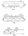
- a zero flow measuring channel 11 provided (see FIG 1).
- an ultrasonic flow meter are two ultrasound transmit / receive transducers 3.4 on attached to the (upper) side wall of a measuring tube, which forms the flow channel 1.
- the two ultrasound transmit / receive transducers 3.4 scan through the flow channel 1 in this exemplary embodiment alternately on a W-shaped Ultrasonic path 2, which is significantly longer than the direct one Distance between both transducers 3.4.
- the flow channel 1 is relatively narrow here and is selected by appropriately selected converter 3.4 with a large Diameter very well covered, which means very good transmission of the flow channel 1 with ultrasound Has. This is one of the main reasons for the excellent Measuring linearity of the measuring tube used.
- the measuring tube is generally not directly related to the surroundings in connection, but is in a drawing Steel box, not shown, for the measuring tube under provides other inlet volumes.
- the steel box is complete filled with the medium gas or liquid, the Flow rate should be measured. From the in the Box contained supply flows the medium m into the measuring tube and thence to an outlet, which, however, is tight from the inlet volume is separated. So far, the ultrasonic flow meter is known and does not require any further description.
- the two channels 1.11 arranged in parallel have in the present case Embodiment according to FIG 1 a common Partition wall 12.
- the ultrasound transmit / receive transducers 3, 4 are - As in the prior art - obliquely on a side wall of the Flow channel 1 attached and sound through the flow channel 1 not only on the W-shaped ultrasonic path 2, but at the same time also the zero flow measuring channel 11, which it according to FIG 1 also cover.
- the actual flow channel 1 also transmits very well.
- the zero flow measuring channel 11 contains the same medium m as the flow channel 1, the medium m here, however, at least in relation almost rests on the transmission.
- the sonication in the Zero flow measuring channel 11 is not W-shaped, but by means of two reflections almost directly (see FIG 2), see above that the distance between the two ultrasound transmit / receive transducers 3.4 practically the effective ultrasonic path 13 in the zero flow measuring channel 11. This results in comparison to the W-shaped Ultrasonic path 2 a significantly shorter ultrasonic transit time T2.
- the quality of the transmission of the zero flow measuring channel 11 is not particularly critical.
- the pulse shape and the reception level of the ultrasonic signals in the flow channel 1 and in the zero flow measuring channel 11 are approximately the same. Is a box designated 10.
- FIG. 2 illustrates that in the flow channel 1 a W-shaped transmission takes place while the ultrasonic path 13 in the zero flow measuring channel 11 directly or in a straight line is (except for the two reflections mentioned).
- the quality of the separation essentially depends on the and fall time of the ultrasound signals involved, i.e. the converter decay time and the acoustic "rattle" due to the structure-borne noise transmission through the measuring tube as well as any other parasitic signals that may be involved from.
- the electronics evaluating the received ultrasound signals therefore has an additional advantage over conventional electronics to complete the task, two arriving in quick succession Process ultrasonic signals and both sound propagation times To measure T1a, T1b or T2a, T2b.
- the flow channel 1 with the zero flow measuring channel 11 only connected at the points where the ultrasonic transceiver 3.4 are located. Otherwise it is the zero flow measuring channel 11 closed.
- Both channels are 1.11 separated from each other by the partition 12 leading to the ultrasonic transducers 3,4 has a gap 14.
- the width of the gap 14 can be determined whether and how much Gas or liquid from flow channel 1 into the zero flow measuring channel 11 should penetrate.
- the flow through the zero flow measuring channel 11 can be made so small that it represents a negligible error for the v measurement. If the gap 14 is reduced and thus the zero flow measuring channel 11 sealed accordingly, the speed the exchange of the medium m between the two channels 1.11 can be reduced to such an extent that the exchange of a diffusion corresponds.
- a small gap 14 between the ultrasonic transducers 3, 4 and the partition 12 still has the Advantage that a structure-borne noise coupling, e.g. about the Measuring tube is kept low.
- the zero flow measuring channel 11 is but suitably upstream from the environment and downstream in relation to the direction of flow in the flow channel 1 open. This makes use of the fact that the actual measuring cell, i.e. the measuring tube with the two channels 1, 11, located within an enveloping steel box. This is the flow through the zero flow measuring channel 11 collinear with that in the flow channel 1. It is through the Pressure difference between the two openings inside the steel box intended for supply and discharge. The one achieved Flow must be set so that the actual flow measurement is only slightly distorted. Depending on the arrangement in the overall box can also flow through the zero flow measuring channel in the opposite direction compared to that take place in the flow channel 1.
- the gas exchange in the zero flow measuring channel 11 is indicated in FIG 5 by an arrow.
- the last-described embodiment can be modified in such a way that that the zero flow measuring channel 11 only at one point the environment inside the steel box is open, so that the exchange of the medium, e.g. of the gas, just by Diffusion is determined.
- the opening is here, e.g. in 6 shown on the opposite to the ultrasonic transducer 3, 4 Page provided in the zero flow measuring channel 11, such as indicated by the arrow. Otherwise this is closed.
- the zero flow measuring channel 11 completely closed, i.e. also in the area the ultrasonic transducer 3.4.
- the partition 12 between Both channels 1, 11 consist here of a porous material or a membrane, e.g. a PTFE film (polytetrafluoroethylene: Teflon®). With this e.g. a gas exchange both through diffusion at very low flow rates as well very little flow through the membrane at higher flow rates take place in flow channel 1.
- the openings in the zero flow measuring channel 11 are not arranged upstream and downstream of the flow measuring channel 1 are. Rather, they can be arranged in the manner be that the zero flow measuring channel 11 from top to bottom or vice versa (FIG 9), i.e. so at right angles to the direction of transmission or the direction of flow in flow channel 1, is flowed through, as indicated by the arrows in the drawing. This can be done by taking appropriate design measures reach the steel box. The river is adjusted so that on the one hand there is a quick exchange of the medium and on the other hand the measurement of the zero flow in the zero flow measuring channel 11 is not disturbed.
- the great advantage of this arrangement is that the flow e.g. with a gas exchange perpendicular to the sonication. So that is but a flow rate-dependent difference in Runtimes excluded by the current.
Landscapes
- Physics & Mathematics (AREA)
- Electromagnetism (AREA)
- Fluid Mechanics (AREA)
- General Physics & Mathematics (AREA)
- Measuring Volume Flow (AREA)
Claims (20)
- Débitmètre aux ultrasons, comprenant un canal (1) d'écoulement dans lequel peut passer un fluide (m), et comprenant deux transducteurs (3, 4) ultrasonores d'émission/réception, qui exposent alternativement le canal (1) d'écoulement, le long d'un premier parcours (2) ultrasonore prescrit, à un signal ultrasonore sur un parcours (2) ultrasonore prescrit, et il est en outre prévu un canal (11) de mesure à écoulement zéro, auquel est associé un parcours (13) ultrasonore, et chaque transducteur (3, 4) ultrasonore d'émission/réception couvrant le canal (1) d'écoulement et le canal (11) de mesure à écoulement zéro de telle sorte que, lors de l'exposition du canal (1) d'écoulement au signal ultrasonore, le canal (11) de mesure à écoulement zéro est en même temps exposé,
caractérisé en ce que les deux parcours (2, 13) ultrasonores sont disposés en parallèle en étant séparés l'un de l'autre, un signal ultrasonore émis par un transducteur (3, 4) ultrasonore d'émission/réception pouvant être reçu par l'autre transducteur (3, 4) ultrasonore respectif d'émission/réception par l'intermédiaire des deux parcours (2, 13) ultrasonores. - Débitmètre aux ultrasons suivant la revendication 1, caractérisé en ce que les parcours (2, 13) ultrasonores sont prévus d'une longueur telle que le transducteur (3 ou 4) ultrasonore d'émission/réception récepteur reçoit successivement les deux signaux ultrasonores passant dans le canal (1) d'écoulement et dans le canal (11) de mesure à écoulement zéro.
- Débitmètre aux ultrasons suivant la revendication 2, caractérisé en ce que le parcours (2) ultrasonore situé dans le canal (1) d'écoulement est plus long que le parcours (13) ultrasonore situé dans le canal (11) de mesure à écoulement zéro.
- Débitmètre aux ultrasons suivant la revendication 3, caractérisé en ce que le parcours (2) ultrasonore dans le canal (1) d'écoulement s'étend en forme de W, et en ce que le parcours (13) ultrasonore dans le canal (11) de mesure à écoulement zéro s'étend sensiblement directement et de façon rectiligne.
- Débitmètre aux ultrasons suivant l'une des revendications précédentes, caractérisé en ce que le canal (1) d'écoulement et le canal (11) de mesure à écoulement zéro sont séparés l'un de l'autre par une cloison (12) séparatrice commune.
- Débitmètre aux ultrasons suivant la revendication 5, caractérisé en ce qu'il existe, dans la cloison (12) séparatrice. une possibilité de passage de fluide (m) entre le canal (1) d'écoulement et le canal (11) de mesure à écoulement zéro uniquement dans la région des transducteurs (3, 4) ultrasonores d'émission/réception.
- Débitmètre aux ultrasons suivant l'une des revendications précédentes, caractérisé en ce que le canal (11) de mesure à écoulement zéro est étanche, un passage de fluide entre le canal (1) d'écoulement et le canal (11) de mesure à écoulement zéro pouvant cependant s'effectuer par diffusion.
- Débitmètre aux ultrasons suivant l'une des revendications précédentes, caractérisé en ce que le canal (1) d'écoulement et le canal (11) de mesure à écoulement zéro sont séparés l'un de l'autre au niveau des transducteurs (3, 4) ultrasonores d'émission/réception, en ce que les deux canaux (1, 11) sont enfermés dans un caisson rempli du fluide (m), et en ce que le canal (11) de mesure à écoulement zéro est ouvert vers l'extérieur en amont et en aval par rapport à la direction d'écoulement du fluide (m) dans le canal (1) d'écoulement.
- Débitmètre aux ultrasons suivant la revendication 8. caractérisé en ce que le canal (11) de mesure à écoulement zéro n'est ouvert vers l'extérieur qu'en un endroit.
- Débitmètre aux ultrasons suivant l'une des revendications précédentes conjointement avec la revendication 6, caractérisé en ce que le canal (11) de mesure à écoulement zéro est entièrement fermé vis-à-vis de l'extérieur, et en ce que la cloison (12) séparatrice entre les deux canaux (1. 11) est, au moins partiellement, réalisée en matériau poreux ou constituée d'une membrane.
- Débitmètre aux ultrasons suivant l'une des revendications précédentes conjointement avec la revendication 5, caractérisé en ce que la cloison (12) séparatrice est constituée d'une membrane dans la région des transducteurs (3, 4) ultrasonores d'émission/réception.
- Débitmètre aux ultrasons suivant l'une des revendications précédentes, caractérisé en ce qu'au moins une ouverture (15) est disposée dans le canal (11) de mesure à écoulement zéro de telle sorte que le fluide (m) passe dans le canal (11) de mesure à écoulement zéro transversalement au guidage des ultrasons dans le canal (11) de mesure à écoulement zéro.
- Débitmètre aux ultrasons suivant l'une des revendications précédentes, caractérisé en ce que les transducteurs (3. 4) ultrasonores d'émission/réception fonctionnent alternativement en émission et en réception
- Débitmétre aux ultrasons suivant l'une des revendications précédentes, caractérisé en ce que le canal (11) de mesure à écoulement zéro est rempli du même fluide (m) que le canal (1) d'écoulement.
- Débitmètre aux ultrasons suivant l'une des revendications 1 à 5 et/ou 13, caractérisé en ce que le canal (11) de mesure à écoulement zéro est rempli d'un autre fluide que le canal (1) d'écoulement.
- Débitmètre aux ultrasons suivant l'une des revendications précédentes, caractérisé en ce que le fluide (m) est pratiquement stagnant dans le canal (11) de mesure à écoulement zéro.
- Débitmètre aux ultrasons suivant l'une des revendications précédentes, caractérisé en ce que le fluide (m) est un gaz ou un liquide.
- Procédé de mesure de débit par ultrasons, selon lequel des transducteurs (3, 4) ultrasonores d'émission/réception exposent aux ultrasons un canal (1) d'écoulement, dans lequel passe un fluide (m), le long d'un premier parcours (2) ultrasonore, et un canal (11) de mesure à écoulement zéro le long d'un second parcours (13) ultrasonore, le transducteur (3 ou 4) ultrasonore d'émission/réception respectivement émetteur exposant simultanément aux ultrasons les deux canaux (1, 11),
caractérisé en ce que l'autre transducteur (4 ou 3) ultrasonore d'émission/réception, alors récepteur, reçoit les signaux ultrasonores qui se propagent séparément l'un de l'autre dans les deux canaux (1, 11) le long des deux parcours (2, 13) ultrasonores. - Procédé suivant la revendication 18, caractérisé en ce que le signal ultrasonore est plusieurs fois réfléchi dans un des canaux (1 ou 11), de sorte que le parcours (2, 13) ultrasonore associé est rendu plus long.
- Procédé suivant la revendication 18 ou 19, caractérisé en ce que le transducteur (4) ultrasonore d'émission/réception respectivement récepteur reçoit successivement les signaux ultrasonores qui se propagent dans les canaux (1, 11).
Applications Claiming Priority (3)
| Application Number | Priority Date | Filing Date | Title |
|---|---|---|---|
| DE4422367 | 1994-06-27 | ||
| DE19944422367 DE4422367C1 (de) | 1994-06-27 | 1994-06-27 | Ultraschall-Durchflußmesser mit kontinuierlicher Nullfluß-Kalibrierung |
| PCT/DE1995/000817 WO1996000375A1 (fr) | 1994-06-27 | 1995-06-27 | Debitmetre ultrasonore a etalonnage continu sur ecoulement zero |
Publications (2)
| Publication Number | Publication Date |
|---|---|
| EP0767896A1 EP0767896A1 (fr) | 1997-04-16 |
| EP0767896B1 true EP0767896B1 (fr) | 1998-11-18 |
Family
ID=6521554
Family Applications (1)
| Application Number | Title | Priority Date | Filing Date |
|---|---|---|---|
| EP95924832A Expired - Lifetime EP0767896B1 (fr) | 1994-06-27 | 1995-06-27 | Debitmetre ultrasonore a etalonnage continu sur ecoulement zero |
Country Status (3)
| Country | Link |
|---|---|
| EP (1) | EP0767896B1 (fr) |
| DE (1) | DE4422367C1 (fr) |
| WO (1) | WO1996000375A1 (fr) |
Families Citing this family (6)
| Publication number | Priority date | Publication date | Assignee | Title |
|---|---|---|---|---|
| DE19617961C2 (de) * | 1996-05-06 | 2001-05-23 | Igl Ingenieur Gemeinschaft Luf | Verfahren zur Messung der Strömungsgeschwindigkeit von gasförmigen oder flüssigen Medien mittels Ultraschall sowie zur Durchführung des Verfahrens geeignetes Meßgerät |
| DE10312034B3 (de) | 2003-03-06 | 2004-03-18 | Krohne Ag | Ultraschalldurchflußmeßverfahren |
| DE102008002027A1 (de) * | 2008-05-28 | 2009-12-03 | Endress + Hauser Flowtec Ag | Messzelle, welche lösbar an einer dafür vorgesehenen Messvorrichtung anbringbar ist |
| DE102018006381B4 (de) * | 2018-08-11 | 2022-05-12 | Diehl Metering Gmbh | Verfahren zum Betrieb einer Messeinrichtung |
| PL3929542T3 (pl) | 2020-06-26 | 2023-11-06 | Sick Engineering Gmbh | Testowanie przepływomierza ultradźwiękowego |
| CN114345673B (zh) * | 2021-12-30 | 2023-05-30 | 京东方科技集团股份有限公司 | 超声换能器及其制作方法、以及超声换能系统 |
Family Cites Families (4)
| Publication number | Priority date | Publication date | Assignee | Title |
|---|---|---|---|---|
| DE3146477C2 (de) * | 1981-11-24 | 1983-12-08 | Gründer & Hötten GmbH, 4300 Essen | Schaltungsanordnung zur Messung der Geschwindigkeit von strömenden Medien |
| JPS60107524A (ja) * | 1983-11-17 | 1985-06-13 | Fuji Electric Co Ltd | 超音波流量計 |
| DE4010148A1 (de) * | 1990-03-29 | 1991-10-02 | Siemens Ag | Verbesserung fuer einen ultraschall-gas-/fluessigkeits-durchflussmesser |
| US5277070A (en) * | 1991-08-01 | 1994-01-11 | Xecutek Corporation | Ultrasonic gas flow measurement method and apparatus |
-
1994
- 1994-06-27 DE DE19944422367 patent/DE4422367C1/de not_active Expired - Fee Related
-
1995
- 1995-06-27 WO PCT/DE1995/000817 patent/WO1996000375A1/fr not_active Ceased
- 1995-06-27 EP EP95924832A patent/EP0767896B1/fr not_active Expired - Lifetime
Also Published As
| Publication number | Publication date |
|---|---|
| WO1996000375A1 (fr) | 1996-01-04 |
| DE4422367C1 (de) | 1996-02-01 |
| EP0767896A1 (fr) | 1997-04-16 |
Similar Documents
| Publication | Publication Date | Title |
|---|---|---|
| DE10312034B3 (de) | Ultraschalldurchflußmeßverfahren | |
| EP1554549B1 (fr) | Débitmètre | |
| DE60100360T2 (de) | Gleichzeitiges bestimmen von mehrphasigen durchflussmengen und konzentrationen | |
| EP0804717B1 (fr) | Procede de mesure de debit par ultrasons | |
| DE69217207T2 (de) | Verfahren und vorrichtung zur überwachung einer gasströmung, insbesondere einer erdgasströmung | |
| DE102006017676B3 (de) | Verfahren zum Betrieb eines Coriolis-Massendurchflußmeßgeräts | |
| EP1608939B1 (fr) | Dispositif permettant de determiner et/ou de surveiller le debit volumetrique et/ou massique d'un milieu | |
| DE4430223A1 (de) | Ultraschallströmungs-Meßverfahren und Vorrichtung zur Durchführung des Verfahrens | |
| DE10335665B4 (de) | Massendurchflussmessgerät | |
| EP0767896B1 (fr) | Debitmetre ultrasonore a etalonnage continu sur ecoulement zero | |
| DE102017009462A1 (de) | Messeinrichtung zur Ermittlung einer Fluidgröße | |
| EP3940346B1 (fr) | Débitmètre et procédé de mesure du débit d'un fluide | |
| EP3517946B1 (fr) | Procédé de détermination d'une valeur corrigée de la vitesse sonique dépendant de la viscosité dans un fluide à analyser | |
| DE19535848C1 (de) | Vorrichtung zur Messung der akustischen Impedanz von flüssigen Medien | |
| DE69413543T2 (de) | Verbesserungen bezüglich der überwachung von flüssigkeitsströmungen | |
| EP2739943B1 (fr) | Procédé de détermination de débit par ultrasons | |
| EP4242599B1 (fr) | Dispositif de mesure et procédé de détermination d'une grandeur de mesure | |
| DE19617961C2 (de) | Verfahren zur Messung der Strömungsgeschwindigkeit von gasförmigen oder flüssigen Medien mittels Ultraschall sowie zur Durchführung des Verfahrens geeignetes Meßgerät | |
| EP0845661A1 (fr) | Procédé et dispositif pour la mesure de la vitesse d'écoulement d'un milieu | |
| EP0502517B1 (fr) | Dispositif pour la mesure du débit d'un fluide dans un canal d'écoulement | |
| WO2005031369A2 (fr) | Capteur a ultrasons, et procede pour mesurer des vitesses d'ecoulement | |
| EP1731883B1 (fr) | Procédé pour détecter un changement géométrique d'un canal de mesure de débit par ultrasons | |
| EP4033214A1 (fr) | Procédé d'étalonnage d'une unité de mesure de température basée sur la mesure ultrasonique, procédé de mesure de la température d'un milieu, unité de mesure de température et débitmètre à ultrasons | |
| DE19605923C2 (de) | Durchflußmesser | |
| EP1731884B1 (fr) | Procédé de mesure de l'epaisseur d'une couche d'un canal de mesure de débit par ultrasons |
Legal Events
| Date | Code | Title | Description |
|---|---|---|---|
| PUAI | Public reference made under article 153(3) epc to a published international application that has entered the european phase |
Free format text: ORIGINAL CODE: 0009012 |
|
| 17P | Request for examination filed |
Effective date: 19961216 |
|
| AK | Designated contracting states |
Kind code of ref document: A1 Designated state(s): GB |
|
| 17Q | First examination report despatched |
Effective date: 19970627 |
|
| GRAG | Despatch of communication of intention to grant |
Free format text: ORIGINAL CODE: EPIDOS AGRA |
|
| GRAG | Despatch of communication of intention to grant |
Free format text: ORIGINAL CODE: EPIDOS AGRA |
|
| GRAH | Despatch of communication of intention to grant a patent |
Free format text: ORIGINAL CODE: EPIDOS IGRA |
|
| GRAH | Despatch of communication of intention to grant a patent |
Free format text: ORIGINAL CODE: EPIDOS IGRA |
|
| GRAA | (expected) grant |
Free format text: ORIGINAL CODE: 0009210 |
|
| AK | Designated contracting states |
Kind code of ref document: B1 Designated state(s): GB |
|
| GBT | Gb: translation of ep patent filed (gb section 77(6)(a)/1977) |
Effective date: 19990104 |
|
| PLBE | No opposition filed within time limit |
Free format text: ORIGINAL CODE: 0009261 |
|
| STAA | Information on the status of an ep patent application or granted ep patent |
Free format text: STATUS: NO OPPOSITION FILED WITHIN TIME LIMIT |
|
| 26N | No opposition filed | ||
| REG | Reference to a national code |
Ref country code: GB Ref legal event code: IF02 |
|
| PGFP | Annual fee paid to national office [announced via postgrant information from national office to epo] |
Ref country code: GB Payment date: 20060613 Year of fee payment: 12 |
|
| GBPC | Gb: european patent ceased through non-payment of renewal fee |
Effective date: 20070627 |
|
| PG25 | Lapsed in a contracting state [announced via postgrant information from national office to epo] |
Ref country code: GB Free format text: LAPSE BECAUSE OF NON-PAYMENT OF DUE FEES Effective date: 20070627 |