EP0768108A1 - Dispositif de désulfuration de gaz de fumée de chaudière avec moyens de récupération de chaleur - Google Patents
Dispositif de désulfuration de gaz de fumée de chaudière avec moyens de récupération de chaleur Download PDFInfo
- Publication number
- EP0768108A1 EP0768108A1 EP96610039A EP96610039A EP0768108A1 EP 0768108 A1 EP0768108 A1 EP 0768108A1 EP 96610039 A EP96610039 A EP 96610039A EP 96610039 A EP96610039 A EP 96610039A EP 0768108 A1 EP0768108 A1 EP 0768108A1
- Authority
- EP
- European Patent Office
- Prior art keywords
- flue gas
- heat
- absorption tower
- boiler
- heat recovery
- Prior art date
- Legal status (The legal status is an assumption and is not a legal conclusion. Google has not performed a legal analysis and makes no representation as to the accuracy of the status listed.)
- Granted
Links
- UGFAIRIUMAVXCW-UHFFFAOYSA-N Carbon monoxide Chemical compound [O+]#[C-] UGFAIRIUMAVXCW-UHFFFAOYSA-N 0.000 title claims abstract description 266
- 239000003546 flue gas Substances 0.000 title claims abstract description 266
- 238000011084 recovery Methods 0.000 title claims abstract description 73
- 238000010521 absorption reaction Methods 0.000 claims abstract description 110
- 239000002002 slurry Substances 0.000 claims abstract description 90
- 239000002250 absorbent Substances 0.000 claims abstract description 51
- 230000002745 absorbent Effects 0.000 claims abstract description 51
- 238000000605 extraction Methods 0.000 claims abstract description 46
- 239000007788 liquid Substances 0.000 claims abstract description 33
- 238000010248 power generation Methods 0.000 claims abstract description 24
- 238000010438 heat treatment Methods 0.000 claims abstract description 19
- 239000000463 material Substances 0.000 claims description 16
- 238000012856 packing Methods 0.000 claims description 14
- 229910052815 sulfur oxide Inorganic materials 0.000 claims description 9
- 230000006872 improvement Effects 0.000 claims description 7
- XTQHKBHJIVJGKJ-UHFFFAOYSA-N sulfur monoxide Chemical class S=O XTQHKBHJIVJGKJ-UHFFFAOYSA-N 0.000 claims description 7
- XLYOFNOQVPJJNP-UHFFFAOYSA-N water Substances O XLYOFNOQVPJJNP-UHFFFAOYSA-N 0.000 description 51
- RAHZWNYVWXNFOC-UHFFFAOYSA-N Sulphur dioxide Chemical class O=S=O RAHZWNYVWXNFOC-UHFFFAOYSA-N 0.000 description 15
- 238000010276 construction Methods 0.000 description 14
- 238000001704 evaporation Methods 0.000 description 13
- 230000008020 evaporation Effects 0.000 description 13
- 239000003595 mist Substances 0.000 description 13
- 230000003247 decreasing effect Effects 0.000 description 11
- 238000001816 cooling Methods 0.000 description 9
- 230000000694 effects Effects 0.000 description 8
- 235000010269 sulphur dioxide Nutrition 0.000 description 8
- 239000007789 gas Substances 0.000 description 7
- 239000000428 dust Substances 0.000 description 6
- 238000006243 chemical reaction Methods 0.000 description 5
- MWUXSHHQAYIFBG-UHFFFAOYSA-N nitrogen oxide Inorganic materials O=[N] MWUXSHHQAYIFBG-UHFFFAOYSA-N 0.000 description 5
- 238000003303 reheating Methods 0.000 description 5
- 230000009182 swimming Effects 0.000 description 5
- 230000004075 alteration Effects 0.000 description 4
- 238000005260 corrosion Methods 0.000 description 4
- 230000007797 corrosion Effects 0.000 description 4
- 239000012717 electrostatic precipitator Substances 0.000 description 4
- 239000010440 gypsum Substances 0.000 description 4
- 229910052602 gypsum Inorganic materials 0.000 description 4
- 230000009467 reduction Effects 0.000 description 4
- 238000011144 upstream manufacturing Methods 0.000 description 4
- 238000006477 desulfuration reaction Methods 0.000 description 3
- 230000023556 desulfurization Effects 0.000 description 3
- 239000000446 fuel Substances 0.000 description 3
- 239000008235 industrial water Substances 0.000 description 3
- 238000000034 method Methods 0.000 description 3
- 230000008569 process Effects 0.000 description 3
- 239000000779 smoke Substances 0.000 description 3
- 235000019738 Limestone Nutrition 0.000 description 2
- 239000003245 coal Substances 0.000 description 2
- 230000008021 deposition Effects 0.000 description 2
- 239000012535 impurity Substances 0.000 description 2
- 239000006028 limestone Substances 0.000 description 2
- 230000003647 oxidation Effects 0.000 description 2
- 238000007254 oxidation reaction Methods 0.000 description 2
- 230000001376 precipitating effect Effects 0.000 description 2
- ZAMOUSCENKQFHK-UHFFFAOYSA-N Chlorine atom Chemical compound [Cl] ZAMOUSCENKQFHK-UHFFFAOYSA-N 0.000 description 1
- 230000002411 adverse Effects 0.000 description 1
- 239000002956 ash Substances 0.000 description 1
- 239000006227 byproduct Substances 0.000 description 1
- 239000003795 chemical substances by application Substances 0.000 description 1
- 239000000460 chlorine Substances 0.000 description 1
- 229910052801 chlorine Inorganic materials 0.000 description 1
- 230000001276 controlling effect Effects 0.000 description 1
- 239000010881 fly ash Substances 0.000 description 1
- 238000005755 formation reaction Methods 0.000 description 1
- 238000009413 insulation Methods 0.000 description 1
- 238000006386 neutralization reaction Methods 0.000 description 1
- 230000009257 reactivity Effects 0.000 description 1
- 230000001105 regulatory effect Effects 0.000 description 1
Images

Classifications
-
- B—PERFORMING OPERATIONS; TRANSPORTING
- B01—PHYSICAL OR CHEMICAL PROCESSES OR APPARATUS IN GENERAL
- B01D—SEPARATION
- B01D53/00—Separation of gases or vapours; Recovering vapours of volatile solvents from gases; Chemical or biological purification of waste gases, e.g. engine exhaust gases, smoke, fumes, flue gases, aerosols
- B01D53/34—Chemical or biological purification of waste gases
- B01D53/46—Removing components of defined structure
- B01D53/48—Sulfur compounds
- B01D53/50—Sulfur oxides
- B01D53/501—Sulfur oxides by treating the gases with a solution or a suspension of an alkali or earth-alkali or ammonium compound
- B01D53/504—Sulfur oxides by treating the gases with a solution or a suspension of an alkali or earth-alkali or ammonium compound characterised by a specific device
Definitions
- This invention relates to a flue gas desulfurizer to be added to boiler equipment or the like, and to boiler equipment for utilizing the recovered heat in lower heat utilization equipment.
- This invention also relates to thermal electric power generation equipment provided with a steam extraction feedwater heater for the steam turbine and with a flue gas desulfurizer.
- a flue gas desulfurizer is used to remove sulfur oxides (SO x ) and other gases present in flue gas from boiler equipment and discharge the resulting clean gas into the atmosphere.
- the absorbent slurry needs to be replenished with water in an amount which is evaporated and carried away by the flue gas, resulting in the requirement of a large amount of industrial water.
- such steam increases the total amount of the flue gas, causing an increase in the power consumption of the back-up fan and the size of the ducts extending to the stack.
- thermal electric power generation equipment has been repeatedly improved until now in order to achieve higher efficiency.
- such equipment includes a plurality of high-pressure, intermediate-pressure and low-pressure steam turbines and a large number of extraction feedwater heaters for heating boiler feedwater successively by use of steam extracted from various points of each turbine.
- it has been very difficult to further enhance the thermal efficiency in the complicatedly constructed steam cycle system of thermal electric power generation equipment.
- a flue gas desulfurizer in accordance with the present invention has an absorption tower for bringing untreated flue gas into gas-liquid contact with an absorbent slurry, and includes heat recovery means for recovering heat from the flue gas passing through the flue gas inlet section of the absorption tower prior to gas-liquid contact.
- the flue gas desulfurizer of the present invention also includes heat recovery means for recovering heat from the absorbent slurry circulating through the absorption tower.
- the amount of heat recovered by the heat recovery means is preset so that the temperature of the treated flue gas discharged from the flue gas outlet section of the absorption tower will not be higher than the saturation temperature for the moisture content of the untreated flue gas.
- Boiler equipment in accordance with the present invention includes a flue gas desulfurizer having an absorption tower for bringing flue gas produced in a boiler into gas-liquid contact with an absorbent slurry, heat recovery means for recovering heat from the flue gas passing through the absorption tower and/or the absorbent slurry circulating through the absorption tower, heat transport means for transporting the heat recovered by the heat recovery means to heat utilization equipment, and heat release means for releasing the heat transported by the heat transport means as an energy source for the heat utilization equipment.
- the aforesaid heat recovery means recovers heat at least from the flue gas passing through the flue gas inlet section of the absorption tower prior to gas-liquid contact.
- the amount of heat recovered by the heat recovery means is preset so that the temperature of the treated flue gas discharged from the flue gas outlet section of the absorption tower will not be higher than the saturation temperature for the moisture content of the untreated flue gas.
- a flue gas desulfurizer When a flue gas desulfurizer is provided with means for recovering heat from the flue gas passing through the flue gas inlet section of the absorption tower thereof prior to gas-liquid contact, a high degree of heat recovery can be achieved and, at the same time, the amount of steam generated in the absorption tower can be reduced. This makes it possible to reduce the amount of water used and the power consumption of the back-up fan located behind the absorption tower, or decrease the size of equipment installed on the downstream side of the absorption tower. Moreover, since the temperature of the absorbent slurry within the absorption tower is steadily lowered, the reactivity in the absorption reaction of sulfur oxides is enhanced to bring about an improvement in desulfurization performance.
- the amount of water evaporated from the slurry within the absorption tower and carried away by the flue gas can be reduced to approximately zero by presetting the amount of heat recovered by the heat recovery means so that the temperature of the treated flue gas discharged from the outlet of the absorption tower will not be higher than the saturation temperature for the moisture content of the untreated flue gas.
- the amount of water used can be reduced markedly.
- the thermal energy recovered from the flue gas in the flue gas desulfurizer can be utilized as an energy source for lower heat utilization equipment. Consequently, the effective utilization of thermal energy can practically and readily be achieved without modifying the boiler and the equipment associated therewith. For example, when heat is recovered from the absorption tower, heat utilization systems such as greenhouses, heated swimming pools and district heating systems can be extended or newly constructed without requiring any alteration such as an increase in boiler capacity. Moreover, additional heat recovery can be effected even in thermal electric power generation equipment and the like wherein further energy recovery has conventionally been regarded as impossible from a practical point of view.
- heat recovery does not interfere with the operation of the boiler equipment or the flue gas desulfurizer, but is effective, for example, in reducing the amount of water used in the flue gas desulfurizer.
- Thermal electric power generation equipment in accordance with the present invention includes a plurality of extraction feedwater heaters for heating boiler feedwater with a part of the steam extracted from steam turbines, a flue gas desulfurizer having an absorption tower for bringing flue gas produced in a boiler into gas-liquid contact with an absorbent slurry to remove sulfur oxides present in the flue gas, and means for recovering heat from the flue gas passing through the absorption tower and/or the absorbent slurry within the absorption tower, whereby boiler feedwater is preheated by the recovered heat and then introduced into the extraction feedwater heaters.
- the boiler feedwater can be preheated by using one or more heat exchangers as the heat recovery means and disposing the heat exchangers at one or more positions selected from the flue gas inlet section of the absorption tower, the inside of the packing material, the inside of the bottom tank, the circulation system of the absorbent slurry, and the flue gas outlet section.
- the boiler feedwater can be more efficiently heated by disposing such a heat exchanger in the flue gas inlet section of the absorption tower.
- the amount of steam extracted from the steam turbines can be reduced. As a result, the power output of the steam turbines can be improved beyond the conventionally recognized limits.
- a heat exchanger for recovering heat from the flue gas passing through the flue gas inlet section of the absorption tower prior to gas-liquid contact is employed as the heat recovery means, a high degree of heat recovery can be achieved to cause a marked increase in power output.
- such heat recovery does not interfere with the operation of the flue gas treatment system, but can reduce the amount of water used owing to a temperature drop of the absorption tower of the flue gas desulfurizer.
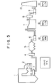
- FIG. 5 is a schematic view showing the typical construction of boiler equipment provided with such a flue gas desulfurizer and the temperature and moisture content of flue gas at various points.
- Flue gas discharged from a boiler 1 is freed of nitrogen oxides (NO x ) in a denitrator 2 attached to boiler 1, passed through an air heater (AH) 3 and the heat recovery section 4 of a gas-gas heater (GGH), and introduced into an electrostatic precipitator (EP) 5 where dust such as fly ash is removed therefrom. Then, by means of an induced draft fan (IDF) 6, the flue gas is introduced into a desulfurizer 7 where sulfur dioxides (predominantly sulfur dioxide) are removed therefrom. Thereafter, the flue gas is passed through the reheating section 8 of the gas-gas heater (GGH) and then discharged from a stack into the atmosphere by means of a back-up fan (BUF) 9.
- AH air heater
- EP electrostatic precipitator
- flue gas desulfurizer 7 used for this purpose, one of the wet absorption type in which flue gas is brought into a gas-liquid contact with an absorbent slurry so as to absorb and remove sulfur dioxide present in the flue gas is widely used in recent years because of its high degree of desulfurization and the like.
- the temperature of the flue gas is typically about 135 °C just behind air heater (AH) 3 and, when coal is used as the fuel, its moisture content is about 8%.
- AH air heater
- the temperature of the flue gas is lowered to about 90 °C as a result of cooling in heat recovery section 4, and the like.
- the temperature of the flue gas is further lowered by contact with an absorbent slurry and, in the case of a coal-fired boiler, typically reaches about 48 °C.
- the temperature of the flue gas at the outlet of flue gas desulfurizer 7 depends on the flow rate and temperature of the introduced flue gas, the gas-liquid contact capacity of flue gas desulfurizer 7, and the like. Since this gas-liquid contact capacity and the like are preset according to the properties (such as sulfur dioxide concentration) of the flue gas, the temperature of the flue gas at the outlet of flue gas desulfurizer 7 eventually depends almost uniquely on the properties of the fuel. For example, this temperature is typically about 48°C when coal is used as the fuel.
- the moisture content of the flue gas at the outlet of flue gas desulfurizer 7 is equal to the saturation level at 48 °C (i.e., about 11%).
- the amount of water evaporated in the absorption tower of flue gas desulfurizer 7 is about 75 t/h.
- the flue gas is heated to about 90 °C in reheating section 8 and discharged from stack 10.
- the temperature of the flue gas must be raised to about 90°C in reheating section 8. Its purpose is to prevent the corrosion of downstream equipment, prevent the flue gas discharged into the atmosphere from being converted to white smoke, and secure its diffusibility. Specifically, unless the temperature of the flue gas is raised to about 90 °C or above, there is a possibility that steam condensate will be produced, and an expensive corrosion-resistant material needs to be used for components such as the ducts extending to stack 10, and back-up fan 9. Moreover, the flue gas discharged into the atmosphere tends to be converted to white smoke, and its desired diffusibility is not obtained. Consequently, when the temperature of the flue gas is so low that its satisfactory diffusibility is not obtained and the smoke does not rise high, the height of the stack itself needs to be increased so as to meet the emission requirements.
- FIG. 1 is a schematic view showing a part of boiler equipment for supplying the heat recovered from a flue gas desulfurizer to lower heat utilization equipment 11 according to the present invention, and also showing the temperatures and moisture contents of flue gas at various points.
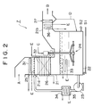
- FIG. 2 is a schematic view showing an example of the construction of an essential part of a flue gas desulfurizer to which the present invention is applied, and also showing various heat recovery means.
- elements similar to those included in the conventional boiler equipment shown in FIG. 5 are designated by the same reference numerals, and the explanation thereof is omitted unless occasion demands.
- the heat energy recovered from a flue gas desulfurizer 7 is supplied to lower heat utilization equipment 11 such as greenhouses, heated swimming pools and district heating systems, and utilized as an energy source therefor, as shown in FIG. 1.
- flue gas desulfurizer 7 is provided with heat recovery means 12, heat transport means 13 for transporting the recovered heat to lower heat utilization equipment 11, and heat release means 14 for releasing the transported heat as an energy source for lower heat utilization equipment 11.
- surplus steam and/or effluent steam from the boiler equipment may be used as part of the aforesaid energy source in combination with the recovered heat.
- flue gas desulfurizer 7 is of the tank oxidation type. Specifically, an absorbent slurry S1 (e.g., a limestone slurry) is supplied from a bottom tank 22 to header pipes 25 disposed in the flue gas inlet section 21a of an absorption tower 21 by means of a circulating pump 23, and injected into untreated flue gas A to absorb and remove sulfur dioxide present in the flue gas. The resulting flue gas is discharged from a flue gas outlet section 21b as treated flue gas B.
- the absorbent slurry injected from header pipes 25 further absorbs sulfur dioxide while flowing downward through the packing material 26 of absorption tower 21, and is accumulated in tank 22.
- Tank 22 is equipped with a rotating arm type air sparger 24 which is rotated horizontally by means of a motor (not shown) to blow air C into tank 22 in the form of fine bubbles while agitating the slurry.
- a rotating arm type air sparger 24 which is rotated horizontally by means of a motor (not shown) to blow air C into tank 22 in the form of fine bubbles while agitating the slurry.
- the predominant reaction occurring in the flue gas desulfurizer are as follows.
- the slurry S2 having suspended therein gypsum and a small amount of limestone used as the absorbent is withdrawn from tank 22 by means of a slurry pump (not shown) and fed to a solid-liquid separator (not shown), where it is filtered to recover gypsum having a low water content as a by-product.
- a mist eliminator 27 for removing any mist from the outgoing treated flue gas B is installed in the flue gas outlet section 21b of absorption tower 21.
- the mist is returned to tank 22 as recovered water D.
- the water separated in the aforesaid solid-liquid separator is recycled to a tank for absorbent slurry S1 (not shown) and reused as water constituting the absorbent slurry.
- part of the recycled water is suitably withdrawn and disposed of so that impurities (such as chlorine) exerting an adverse influence on the absorption reaction of sulfur dioxide and the formation reaction of gypsum may not accumulate therein.
- impurities such as chlorine
- industrial water is suitably supplied to the recycled water.
- the amount of water carried away as a result of evaporation in the absorption tower is markedly smaller than that in the conventional process, as will be described later. Consequently, the aforesaid make-up water is also reduced significantly.
- heat recovery means 12 of flue gas desulfurizer 7 is more specifically explained with reference to FIG. 2.
- heat recovery means 12 there may be used, for example, one or more heat exchangers for effecting heat exchange between a circulating heating medium (i.e., boiler feedwater) E and the flue gas and/or absorbent slurry within the absorption tower 21 of flue gas desulfurizer 7.
- a circulating heating medium i.e., boiler feedwater
- a reduction in cost can be achieved, for example, by using industrial water containing anticorrosive and antifreezing agents as the heating medium.
- the heat recovery means can be employed as shown in FIG. 2. They include (i) a heat exchanger comprising a heat transfer tube 31 disposed upstream of header pipes 25 in the flue gas inlet section 21a of absorption tower 21 in order to recover heat from untreated hot flue gas A prior to contact with the absorbent slurry; (ii) a heat exchanger comprising a heat transfer tube 32 disposed downstream of header pipes 25 of absorption tower 21 (for example, within packing material 26) in order to recover heat from the flue gas having undergone gas-liquid contact and from the slurry; (iii) a heat exchanger comprising a heat transfer tube 33 disposed in the slurry within the tank 22 of absorption tower 21 in order to recover heat from the slurry; (iv) a heat exchanger 34 comprising a heat transfer tube 35 installed in the discharge line and/or suction line of circulating pump 23 for delivering the absorbent slurry from tank 22 to header pipes 25, in order to recover heat from the absorbent slurry; and (v)
- Heat recovery means 12 may comprise any one of the above-described heat exchangers or a plurality of such heat exchangers, for example, connected in series. However, in order to achieve a relatively high degree of heat recovery, the heat recovery means 12 should preferably include a heat exchange (comprising heat transfer tube 31) for recovering heat from untreated flue gas A prior to contact with the absorbent slurry.
- a heat exchange comprising heat transfer tube 31 for recovering heat from untreated flue gas A prior to contact with the absorbent slurry.
- the amount of heat recovered by heat recovery means 12 should preferably be preset so that the temperature of treated flue gas B finally discharged from absorption tower 21 will not be higher than the saturation temperature for the moisture content of untreated flue gas A.
- the heat exchanger(s) and control the circulation rate of heating medium E so that the temperature of treated flue gas B will be about 40°C or below.
- this heat recovery means 12 may be provided with control means (not shown) for automatically adjusting the amount of heat recovered to the aforesaid target value.
- this control means may consist of a concentration sensor for detecting the moisture content of untreated flue gas A, a temperature sensor for detecting the gas temperature of treated flue gas B discharged from the flue gas outlet section 21a of absorption tower 21, a flow control valve for regulating the flow rate of the aforesaid heating medium E, and a controller for calculating a target temperature from the detected value of the aforesaid concentration sensor and controlling the opening of the aforesaid flow control valve so that the detected value of the aforesaid temperature sensor will be maintained in the vicinity of this target value.
- Heat transport means 13 for transporting the recovered heat to lower heat utilization equipment 11 may comprise, for example, piping for conveying heating medium E under thermal insulation against its surroundings, and a feed pump.
- Heat release means 14 may comprise a heat exchanger for releasing the heat of heating medium E in lower heat utilization equipment 11, such as a heat exchanger for heating the air within a greenhouse or a heat exchanger for heating the water of a swimming pool.
- heat recovery means 12 functions to recover heat from the flue gas passing through absorption tower 21 and/or the absorbent slurry circulating through absorption tower 21, and lower heat utilization equipment 11 can be effectively operated by using this heat.
- lower heat utilization equipment 11 can also be operated by using surplus steam or effluent steam from the boiler equipment in combination with the heat recovered from the flue gas desulfurizer.
- heat recovery means 12 When a heat exchanger (comprising heat transfer tube 31) for recovering heat from untreated flue gas A prior to contact with the absorbent slurry is employed as heat recovery means 12, the evaporation in the succeeding gas-liquid contact region can be suppressed in proportion to the degree of cooling of the flue gas, and the steady-state temperature of the slurry within the absorption tower and the steady-state temperature of treated flue gas B can also be lowered correspondingly.
- the temperature of the flue gas in the flue gas outlet section of the flue gas desulfurizer is preset at a value (e.g., 40 °C or below) which is not higher than the saturation temperature for the moisture content of untreated flue gas A, the evaporation in the downstream gas-liquid contact region is theoretically zero, and the steady-state temperature of the slurry within the absorption tower and the steady-state temperature of treated flue gas B are equilibrated at that saturation temperature or below. Actually, they are affected by the heat generated by the reactions within tank 22, but its effect is very slight and little worth consideration.
- a heat exchanger for recovering heat from the flue gas present downstream of header pipes 25 (e.g., within packing material 26) and from the absorbent slurry
- a heat exchanger for recovering heat from the absorbent slurry within tank 22, or a heat exchanger (comprising heat transfer tube 35) for recovering heat from the absorbent slurry in the pipeline for circulating it, is employed as heat recovery means 12, the heat transmitted, or to be transmitted, from the flue gas to the slurry is recovered continuously.
- the evaporation in the gas-liquid contact region can be suppressed in proportion to the degree of cooling, and the steady-state temperature of the slurry within the absorption tower and the steady-state temperature of treated flue gas B can also be lowered correspondingly. Also in this case, if the amount of heat recovered by the heat exchanger is preset so that the temperature of the slurry and the flue gas within the absorption tower will not be higher than the saturation temperature for the moisture content of untreated flue gas A (e.g., 40 °C or below), the evaporation in the gas-liquid contact region is theoretically zero.
- heat recovery means 12 When a heat exchanger (comprising heat transfer tube 36) for recovering heat from the flue gas passing through the flue gas outlet section 21b of absorption tower 21 is employed as heat recovery means 12, steam is once generated in the flue gas inlet section 21a of absorption tower 21 as a result of the gas-liquid contact of untreated flue gas A with the slurry. Unless other heat exchanges are installed, the temperature of the slurry and the flue gas within the absorption tower is similar to that observed in the prior art (e.g., 48 °C) and the moisture content is also similar to that observed in the prior art (e.g., 11%).
- the temperature on the outlet side of this heat exchanger i.e., the temperature of treated flue gas B
- a value e.g., 40 °C or below
- the saturation temperature for the moisture content e.g., 8%
- the evaporation i.e., the amount of water evaporated and carried away from the slurry
- the evaporation can also be reduced in proportion to the overall degree of cooling by heat recovery.
- the evaporation can be reduced to zero by properly presetting the amount of heat recovered.
- Thermal energy can be recovered from flue gas produced in a boiler and utilized effectively without altering the basic construction of the current boiler and equipment associated therewith.
- a heat exchanger for recovering heat from untreated flue gas A prior to contact with the absorbent slurry is employed as heat recovery means 12, a high degree of heat recovery can be achieved as a result of heat exchange with untreated flue gas A having the highest temperature.
- the calculated temperature of the heating medium in heat release means 14 is about 70 °C (see FIG. 1), provided that the flue gas is cooled to the saturation temperature (i.e., about 40 °C) by circulating the heating medium (i.e., water) at a flow rate of about 700 t/h.
- the recovered heat is sufficient for use as a heat source for greenhouses, heated swimming pools and the like.
- the moisture content of treated flue gas B is equal to or less than that of untreated flue gas A and the evaporation in the absorption tower (strictly speaking, the amount of water evaporated and carried away from the absorption tower) is zero. Consequently, about 75 t/h of water can be saved in the case, for example, of a coal-fired boiler of the 1,000 MW class.
- the capacity (or power consumption) of back-up fan 9 is maintained at the current level, the cross-sectional areas of the flow paths in the absorption tower and the like can be decreased significantly and, therefore, the size of the equipment can be reduced.
- the moisture content of the treated flue gas can be decreased from 11% to 8% or less by lowering its temperature from the conventional level of 48 °C to 40 °C. This means that the total amount of the treated flue gas is decreased by 3% or more.
- heat recovery means 12 When a heat exchanger installed in the discharge line or suction line of circulating pump 23 is employed as heat recovery means 12, heat can be recovered from the current flue gas desulfurizer by making a simple alteration which comprises, for example, connecting a ready-made heat exchanger in the line.
- the present invention is not limited to the flue gas desulfurizer and boiler equipment described above in connection with this embodiment, but may be practiced in various ways.
- the present invention can be applied to any equipment using a boiler and any equipment requiring a flue gas desulfurizer. That is, similar effects can also be achieved by applying the present invention, for example, to refuse disposal equipment and marine steam engines.
- heat recovery means there may be used not only heat exchangers comprising heat transfer tubes as described above, but also a jacket provided on the absorption tower for passing a heating medium therethrough.
- the heat transport means may also consist, for example, of heat pipes.
- thermal electric power generation equipment in accordance with one embodiment of the present invention is described below. First, a steam cycle system for use in this embodiment is explained.
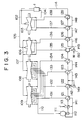
- FIG. 3 is a schematic view showing the construction of a steam cycle system for use in this thermal electric power generation equipment.
- High-pressure steam generated in a boiler 1 is conveyed through a line 102 and introduced into a high-pressure turbine 103 where it expands and does work by driving turbine blades. Then, the steam is returned to boiler 1 through a line 104, reheated therein, conveyed through a line 105 and introduced into an intermediate-pressure turbine 106 where it does work again.
- the low-pressure steam which has done work and expanded in intermediate-pressure turbine 106 is conveyed through a line 107 and dividedly introduced into two low-pressure turbines 108 and 109 arranged in parallel, where it does further work.
- the steam which has done work and expanded in low-pressure turbines 108 and 109 is conveyed through a line 110 and introduced into a steam condenser 111 whose internal pressure is kept negative to condense the steam.
- the condensate produced in steam condenser 111 is delivered as boiler feedwater by means of a pump 112 and passed through a heater 113 where it is heated with steam J flowing out of the bearing parts of the turbines. Thereafter, the boiler feedwater is successively heated by a large number of extraction feedwater heaters 121-128 and finally fed to boiler 1 through a line 114.
- Extraction feedwater heaters 121, 122, 123 and 124 are extraction feedwater heaters of the so-called surface type in which the boiler feedwater is successively heated with some steam extracted from four stages of low-pressure turbines 108 and 109 through lines 131, 132, 133 and 134, respectively.
- the steam extracted through line 131 after having passed through extraction feedwater heater 121, is conveyed through a line 141 and introduced into steam condenser 111 where it is condensed to form part of the boiler feedwater.
- the steam extracted through line 132, after having passed through extraction feedwater heater 122, is conveyed through a line 142 and mixed in the boiler feedwater on the inlet side of extraction feedwater heater 123 to form part of it.
- Extraction feedwater heater 125 is an extraction feedwater heater of the so-called mixing type in which the boiler feedwater is heated by mixing therein some steam extracted from a late stage of intermediate-pressure turbine 106 through a line 135. After being heated by mixing, the boiler feedwater leaves extraction feedwater heater 125 and is introduced into extraction feedwater heater 126 through a line 145.
- Extraction feedwater heaters 126, 127 and 128 are extraction feedwater heaters of the surface type in which the boiler feedwater is successively heated with some steam extracted from a middle stage of intermediate-pressure turbine 106 and from middle and late stages of high-pressure turbine 103 through lines 136, 137 and 138, respectively.
- the steam extracted through line 136 after having passed through extraction feedwater heaters 126, is conveyed through a line 146 and introduced into extraction feedwater heater 125 where it is mixed in the boiler feedwater to form part of it.
- the steam extracted through lines 137 and 138, after having passed through extraction feedwater heaters 127 and 128, is conveyed to extraction feedwater heaters 126 and 127 through lines 147 and 148, respectively.
- the steam is introduced into extraction feedwater heater 125 and mixed in the boiler feedwater to form part of it.
- Lines 142 and 145 are provided with pumps 149 and 150 for pressurizing and delivering the boiler feedwater, respectively.
- pump 150 water W is suitably supplied.
- the temperature of the boiler feedwater is typically about 33 °C at the outlet of steam condenser 111, typically about 34 °C at the outlet of heater 113, typically about 64 °C at the outlet of extraction feedwater heater 121, and typically about 84 °C at the outlet of extraction feedwater heater 122.
- the boiler feedwater is typically heated to about 283 °C at the outlet of extraction feedwater heater 128 and fed to boiler 1.
- the amount of feedwater introduced into extraction feedwater heater 121 is about 1,830 t/h and the amount of steam extracted from low-pressure turbines 108 and 109 and fed to extraction feedwater heater 121 through line 131 should usually be about 98.2 t/h.
- this thermal electric power generation equipment is provided with a flue gas treatment system in which the flue gas produced in boiler 1 is treated to remove dust, sulfur oxides (SO x ) and the like therefrom and discharge the resulting clean flue gas into the atmosphere.
- a flue gas treatment system in which the flue gas produced in boiler 1 is treated to remove dust, sulfur oxides (SO x ) and the like therefrom and discharge the resulting clean flue gas into the atmosphere.
- the condensate produced in steam condenser 111 (by condensing steam from the low-pressure turbines shown in FIG. 3) is introduced into heater 113 by means of pump 112 and heated with steam J flowing out of the bearing parts of the turbines.
- the heated condensate is conveyed through a line 162 and introduced into the heat recovery means 161 (specifically, in the form of a heat exchanger) of a flue gas desulfurizer 7 where it is heat with flue gas and/or an absorbent slurry.
- the heated condensate is introduced into extraction feedwater heater 121 where it is further heated with some steam extracted from the low-pressure turbines shown in FIG. 3 through line 131. Finally, this condensate is used as boiler feedwater.
- the thermal electric power generation equipment in accordance with this embodiment uses the flue gas desulfurizer which has been described above with reference to FIG. 2.
- heat recovery means 161 functions to recover heat from the flue gas passing through absorption tower 21 (FIG. 2) or the absorbent slurry within absorption tower 21, and feedwater is heated by this heat prior to introduction into extraction feedwater heater 121. Consequently, when the temperature of the feedwater on the downstream side of extraction feedwater heater 121 is maintained at the current level, the amount of steam extracted through line 131 can be reduced significantly.
- heat recovery means 161 when a heat exchanger (comprising heat transfer tube 31) for recovering heat from untreated flue gas A prior to contact with the absorbent slurry is employed as heat recovery means 161, the evaporation from the absorbent slurry in the succeeding gas-liquid contact region can be suppressed in proportion to the degree of cooling of the flue gas, and the steady-state temperature of the slurry within the absorption tower and the steady-state temperature of treated flue gas B can also be lowered correspondingly. Actually, they are affected by the heat generated by the reactions within tank 22, but its effect is very slight and little worth consideration.
- a heat exchanger for recovering heat from the flue gas present downstream of header pipes 25 (e.g., within packing material 26) and from the slurry
- a heat exchanger for recovering heat from the slurry within tank 22
- a heat exchanger for recovering heat from the absorbent slurry in the pipeline for circulating it
- heat recovery means 161 the heat transmitted, or to be transmitted, from the flue gas to the slurry is recovered continuously.
- the evaporation from the absorbent slurry in the gas-liquid contact region can be suppressed in proportion to the degree of cooling, and the steady-state temperature of the slurry within the absorption tower and the steady-state temperature of treated flue gas B can also be lowered correspondingly.
- this flue gas is cooled in flue gas outlet section 21b, so that the water once evaporated is condensed in flue gas outlet section 21b in proportion to the degree of cooling and recovered by mist eliminator 27. Eventually, the amount of water evaporated and carried away from the slurry within the absorption tower can be reduced markedly.
- the evaporation i.e., the amount of water evaporated and carried away from the slurry
- the evaporation can also be reduced in proportion to the overall degree of cooling by heat recovery.
- the present invention is not limited to the above-described embodiment of thermal electric power generation equipment, but may be practiced in various ways.
- the heat recovery means of the present invention there may be used not only heat exchangers comprising heat transfer tubes as described above, but also a jacket provided on the absorption tower for passing a heating medium therethrough.
- the position at which the boiler feedwater is heated by the heat recovered from the flue gas desulfurizer is not necessarily limited to the inlet side of extraction feedwater heater 121 nearest to the steam condenser as illustrated in connection with the above-described embodiment.
- the boiler feedwater may be withdrawn from the inlet side of the second extraction feedwater heater 122 and heated in the heat exchanger installed in the absorption tower of the flue gas desulfurizer. Also in this case, similar effects can be achieved, though there may be variation in degree.
- the above-described embodiment makes it possible to recover heat more efficiently from the flue gas and the like present in the absorption tower.
- Part of the thermal energy of flue gas produced in a boiler can be utilized to heat feedwater prior to introduction into extraction feedwater heater 121, without altering the construction of the current equipment such as the boiler, turbines and extraction feedwater heaters. This makes it possible to reduce the amount of steam extracted from the low-pressure turbines while maintaining the temperature of the feedwater downstream of the extraction feedwater heater at the current level. Consequently, the power outputs of the low-pressure turbines can be improved far beyond the conventionally recognized limits.
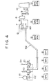
- the feedwater (having a temperature of about 34 °C and a flow rate of about 1,830 t/h) before being introduced into extraction feedwater heater 121 is heated to about 48 °C as shown in FIG. 4.
- the temperature of treated flue gas B is about 43 °C and its moisture content is about 8.3%, as shown in FIG. 4.
- the moisture content is about 8.3%, as shown in FIG. 4.
- treated flue gas B Since the moisture content of treated flue gas B is markedly decreased, the total amount of gas which must be withdrawn from the absorption tower and discharged into the atmosphere through the stack (i.e., treated flue gas B) can be reduced significantly. Consequently, if the cross-sectional areas of the flow paths in the absorption tower and mist eliminator 27 and further in the duct extending to reheating section 8 or stack 10 are maintained at the current levels, the capacity (or power consumption) of back-up fan 9 can be significantly decreased because of a marked reduction in pressure loss. Alternatively, if the capacity (or power consumption) of back-up fan 9 is maintained at the current level, the cross-sectional areas of the flow paths in the absorption tower and the like can be decreased significantly and, therefore, the size of the equipment can be reduced.
- heat recovery means 161 When a heat exchanger installed in the discharge line or suction line of circulating pump 23 is employed as heat recovery means 161, heat can be recovered from the current flue gas desulfurizer by making a simple alteration which comprises, for example, connecting a ready-made heat exchanger in the line.
Landscapes
- Engineering & Computer Science (AREA)
- Chemical & Material Sciences (AREA)
- Health & Medical Sciences (AREA)
- Biomedical Technology (AREA)
- Environmental & Geological Engineering (AREA)
- Analytical Chemistry (AREA)
- General Chemical & Material Sciences (AREA)
- Oil, Petroleum & Natural Gas (AREA)
- Chemical Kinetics & Catalysis (AREA)
- Treating Waste Gases (AREA)
Applications Claiming Priority (6)
| Application Number | Priority Date | Filing Date | Title |
|---|---|---|---|
| JP265287/95 | 1995-10-13 | ||
| JP7265287A JPH09103641A (ja) | 1995-10-13 | 1995-10-13 | 排煙脱硫装置及びボイラ設備 |
| JP26528795 | 1995-10-13 | ||
| JP266626/95 | 1995-10-16 | ||
| JP7266626A JPH09112211A (ja) | 1995-10-16 | 1995-10-16 | 火力発電設備 |
| JP26662695 | 1995-10-16 |
Publications (2)
| Publication Number | Publication Date |
|---|---|
| EP0768108A1 true EP0768108A1 (fr) | 1997-04-16 |
| EP0768108B1 EP0768108B1 (fr) | 2002-03-20 |
Family
ID=26546923
Family Applications (1)
| Application Number | Title | Priority Date | Filing Date |
|---|---|---|---|
| EP96610039A Expired - Lifetime EP0768108B1 (fr) | 1995-10-13 | 1996-10-11 | Dispositif de désulfuration de gaz de fumée de chaudière avec moyens de récupération de chaleur |
Country Status (4)
| Country | Link |
|---|---|
| US (1) | US5878675A (fr) |
| EP (1) | EP0768108B1 (fr) |
| DK (1) | DK0768108T3 (fr) |
| ES (1) | ES2171217T3 (fr) |
Cited By (6)
| Publication number | Priority date | Publication date | Assignee | Title |
|---|---|---|---|---|
| WO2000009948A1 (fr) | 1998-08-17 | 2000-02-24 | Rupert Merkl | Procede de reduction des rejets de matieres polluantes de petites installations de chauffage avec prise en consideration de la puissance calorifique, et dispositif utilise a cet effet |
| EP1844842A2 (fr) | 2006-04-13 | 2007-10-17 | The Babcock & Wilcox Company | Procédé pour le contrôle de la concentration en humidité d'un gaz de carburant de combustion |
| EP2911983A4 (fr) * | 2012-10-23 | 2016-08-31 | Babcock & Wilcox Co | Système et procédé permettant de lutter contre l'accumulation de tartre dans une unité de désulfuration de gaz effluent humide (wfgd) |
| CN112361317A (zh) * | 2020-11-02 | 2021-02-12 | 上海明华电力科技有限公司 | 用于废水浓缩工艺的高温飞灰余热回收装置及方法 |
| CN114001491A (zh) * | 2021-11-30 | 2022-02-01 | 华能营口热电有限责任公司 | 一种基于毛细管与吸收式热泵的脱硫浆液余热回收装置 |
| CN114111094A (zh) * | 2021-11-30 | 2022-03-01 | 中国华能集团清洁能源技术研究院有限公司 | 一种利用机组抽汽与吸收式热泵的脱硫浆液余热回收装置 |
Families Citing this family (14)
| Publication number | Priority date | Publication date | Assignee | Title |
|---|---|---|---|---|
| US6095063A (en) * | 1999-08-26 | 2000-08-01 | Utek Semiconductor Corp. | Exhaust treatment machine |
| CA2370253A1 (fr) * | 2001-02-01 | 2002-08-01 | Mark Entleutner | Appareil thermique producteur d'electricite |
| JP4827307B2 (ja) * | 2001-03-26 | 2011-11-30 | 矢崎総業株式会社 | 空気調和装置 |
| JP5461100B2 (ja) * | 2009-02-27 | 2014-04-02 | 三菱重工業株式会社 | 低品位炭を燃料とする火力発電プラント |
| PL2354651T3 (pl) | 2010-01-18 | 2014-11-28 | General Electric Technology Gmbh | System odzysku ciepła spalin w połączeniu z poprawą odpylania jako rozwiązanie w modernizacji istniejących elektrowni węglowych |
| CN101900492B (zh) * | 2010-08-30 | 2012-05-30 | 中国铝业股份有限公司 | 一种氧化铝焙烧炉烟气余热回收过程的防结疤方法 |
| JP2013000729A (ja) * | 2011-06-21 | 2013-01-07 | Toshiba Corp | 二酸化炭素回収装置および二酸化炭素回収方法 |
| US9657943B2 (en) | 2014-12-16 | 2017-05-23 | Great River Energy | Method and system for reheating flue gas using waste heat to maintain dry chimney stack operation |
| US10221726B2 (en) * | 2015-12-21 | 2019-03-05 | Cockerill Maintenance & Ingenierie S.A. | Condensing heat recovery steam generator |
| CN108434924B (zh) * | 2018-06-07 | 2024-04-19 | 北京国能中电节能环保技术股份有限公司 | 一种烟气消白烟系统和方法 |
| CN111520208A (zh) * | 2020-04-29 | 2020-08-11 | 华能国际电力股份有限公司 | 一种脱硫浆液闪蒸回收烟气余热和水分的系统及方法 |
| CN114033510B (zh) * | 2021-11-30 | 2025-07-22 | 华能营口热电有限责任公司 | 一种利用机组抽汽的脱硫浆液提热取水装置及其工作方法 |
| CN115950281B (zh) * | 2023-01-28 | 2025-08-19 | 北京翰海青天环保科技有限公司 | 一种烟气除尘脱硫余热回收装置 |
| CN116951526A (zh) * | 2023-07-20 | 2023-10-27 | 华能青岛热电有限公司 | 一种利用电厂烟气余热的供暖系统 |
Citations (5)
| Publication number | Priority date | Publication date | Assignee | Title |
|---|---|---|---|---|
| JPS634835A (ja) * | 1986-06-24 | 1988-01-09 | Mitsubishi Heavy Ind Ltd | 排熱回収用熱交換器を内蔵する湿式排煙脱硫装置 |
| EP0298039A2 (fr) * | 1987-06-29 | 1989-01-04 | Füllemann Patent Ag | Procédé et dispositif pour la séparation du bioxyde de souffre contenu dans des gaz, en particulier gaz de fumée |
| EP0499664A1 (fr) * | 1991-02-20 | 1992-08-26 | WIBAU Maschinen GmbH & Co. KG | Procédé pour le traitement par voie chimico-physique de gaz d'échappement d'installations de mélange d'asphalte |
| EP0543767A1 (fr) * | 1991-11-20 | 1993-05-26 | Mitsubishi Jukogyo Kabushiki Kaisha | Procédé pour la fabrication d'articles moulés solides à partir de sous-produits de la désulfuration calcaire-gypse de gaz de fumée par voie humide |
| DE4307608A1 (de) * | 1993-03-05 | 1994-09-15 | Ver Energiewerke Ag | Verfahren und Vorrichtung zur Energienutzung von Rauchgasen in kohlegefeuerten Kraftwerken |
Family Cites Families (15)
| Publication number | Priority date | Publication date | Assignee | Title |
|---|---|---|---|---|
| US3812793A (en) * | 1972-04-19 | 1974-05-28 | Trayler W | Apparatus for treating noxious effluents |
| US3997294A (en) * | 1973-11-24 | 1976-12-14 | Apparatebau Rothemuhle Brandt & Kritzler | Device for treating gases |
| DE2847591C2 (de) * | 1978-11-02 | 1982-12-23 | Stadtwerke Düsseldorf AG, 4000 Düsseldorf | Verfahren sowie Vorrichtung zur Neutralisation saurer Schadstoffe in Rauchgasen von Feuerungsanlagen mit Abwärmenutzung |
| US4305909A (en) * | 1979-10-17 | 1981-12-15 | Peabody Process Systems, Inc. | Integrated flue gas processing system |
| DE3236905C2 (de) * | 1982-10-06 | 1986-01-02 | Gottfried Bischoff Bau kompl. Gasreinigungs- und Wasserrückkühlanlagen GmbH & Co KG, 4300 Essen | Verfahren zur Entschwefelung von Rauchgasen und Vorrichtung zur Durchführung des Verfahrens |
| US4489679A (en) * | 1983-12-12 | 1984-12-25 | Combustion Engineering, Inc. | Control system for economic operation of a steam generator |
| CH658710A5 (de) * | 1984-07-09 | 1986-11-28 | Vth Ag | Vorrichtung zur erhitzung eines fluids und zur reinigung der abgase von feuerungsanlagen. |
| US4660511A (en) * | 1986-04-01 | 1987-04-28 | Anderson J Hilbert | Flue gas heat recovery system |
| US4999167A (en) * | 1989-06-20 | 1991-03-12 | Skelley Arthur P | Low temperature Nox /Sox removal apparatus |
| DE4002434A1 (de) * | 1990-01-27 | 1991-08-01 | Gea Luftkuehler Happel Gmbh | Verfahren und vorrichtung zur entstickung und entschwefelung von heissen abgasen, insbesondere aus feuerungen |
| US5339755A (en) * | 1993-08-10 | 1994-08-23 | The Babcock & Wilcox Company | Dry scrubber with condensing heat exchanger for cycle efficiency improvement |
| US5553555A (en) * | 1994-04-28 | 1996-09-10 | Dasibi Environmental Corporation | System and method for flue gas purification for thermal power units |
| US5534230A (en) * | 1994-07-05 | 1996-07-09 | The Babcock & Wilcox Company | Segmented heat exchanger flue gas treatment |
| US5510087A (en) * | 1994-07-05 | 1996-04-23 | The Babcock & Wilcox Company | Two stage downflow flue gas treatment condensing heat exchanger |
| JP3170158B2 (ja) * | 1994-11-08 | 2001-05-28 | 三菱重工業株式会社 | 気液接触装置及び湿式排煙脱硫装置 |
-
1996
- 1996-08-12 US US08/696,317 patent/US5878675A/en not_active Expired - Fee Related
- 1996-10-11 DK DK96610039T patent/DK0768108T3/da active
- 1996-10-11 EP EP96610039A patent/EP0768108B1/fr not_active Expired - Lifetime
- 1996-10-11 ES ES96610039T patent/ES2171217T3/es not_active Expired - Lifetime
Patent Citations (5)
| Publication number | Priority date | Publication date | Assignee | Title |
|---|---|---|---|---|
| JPS634835A (ja) * | 1986-06-24 | 1988-01-09 | Mitsubishi Heavy Ind Ltd | 排熱回収用熱交換器を内蔵する湿式排煙脱硫装置 |
| EP0298039A2 (fr) * | 1987-06-29 | 1989-01-04 | Füllemann Patent Ag | Procédé et dispositif pour la séparation du bioxyde de souffre contenu dans des gaz, en particulier gaz de fumée |
| EP0499664A1 (fr) * | 1991-02-20 | 1992-08-26 | WIBAU Maschinen GmbH & Co. KG | Procédé pour le traitement par voie chimico-physique de gaz d'échappement d'installations de mélange d'asphalte |
| EP0543767A1 (fr) * | 1991-11-20 | 1993-05-26 | Mitsubishi Jukogyo Kabushiki Kaisha | Procédé pour la fabrication d'articles moulés solides à partir de sous-produits de la désulfuration calcaire-gypse de gaz de fumée par voie humide |
| DE4307608A1 (de) * | 1993-03-05 | 1994-09-15 | Ver Energiewerke Ag | Verfahren und Vorrichtung zur Energienutzung von Rauchgasen in kohlegefeuerten Kraftwerken |
Non-Patent Citations (1)
| Title |
|---|
| PATENT ABSTRACTS OF JAPAN vol. 012, no. 202 (C - 503) 10 June 1988 (1988-06-10) * |
Cited By (10)
| Publication number | Priority date | Publication date | Assignee | Title |
|---|---|---|---|---|
| WO2000009948A1 (fr) | 1998-08-17 | 2000-02-24 | Rupert Merkl | Procede de reduction des rejets de matieres polluantes de petites installations de chauffage avec prise en consideration de la puissance calorifique, et dispositif utilise a cet effet |
| DE19837269A1 (de) * | 1998-08-17 | 2000-02-24 | Rupert Merkl | Vorrichtung und Verfahren zur Verringerung der Schadstoffemission von Heizungskleinanlagen unter gleichzeitiger Einbeziehung der Brennwertnutzung |
| EP1844842A2 (fr) | 2006-04-13 | 2007-10-17 | The Babcock & Wilcox Company | Procédé pour le contrôle de la concentration en humidité d'un gaz de carburant de combustion |
| EP1844842A3 (fr) * | 2006-04-13 | 2007-11-14 | The Babcock & Wilcox Company | Procédé pour le contrôle de la concentration en humidité d'un gaz de carburant de combustion |
| CN101063527B (zh) * | 2006-04-13 | 2011-03-23 | 巴布考克及威尔考克斯公司 | 控制烟道气中水分浓度的方法 |
| EP2911983A4 (fr) * | 2012-10-23 | 2016-08-31 | Babcock & Wilcox Co | Système et procédé permettant de lutter contre l'accumulation de tartre dans une unité de désulfuration de gaz effluent humide (wfgd) |
| CN112361317A (zh) * | 2020-11-02 | 2021-02-12 | 上海明华电力科技有限公司 | 用于废水浓缩工艺的高温飞灰余热回收装置及方法 |
| CN114001491A (zh) * | 2021-11-30 | 2022-02-01 | 华能营口热电有限责任公司 | 一种基于毛细管与吸收式热泵的脱硫浆液余热回收装置 |
| CN114111094A (zh) * | 2021-11-30 | 2022-03-01 | 中国华能集团清洁能源技术研究院有限公司 | 一种利用机组抽汽与吸收式热泵的脱硫浆液余热回收装置 |
| CN114111094B (zh) * | 2021-11-30 | 2023-02-28 | 中国华能集团清洁能源技术研究院有限公司 | 一种利用机组抽汽与吸收式热泵的脱硫浆液余热回收装置 |
Also Published As
| Publication number | Publication date |
|---|---|
| DK0768108T3 (da) | 2002-05-27 |
| ES2171217T3 (es) | 2002-09-01 |
| EP0768108B1 (fr) | 2002-03-20 |
| US5878675A (en) | 1999-03-09 |
Similar Documents
| Publication | Publication Date | Title |
|---|---|---|
| EP0768108B1 (fr) | Dispositif de désulfuration de gaz de fumée de chaudière avec moyens de récupération de chaleur | |
| US12072096B2 (en) | Method and system for improving boiler effectiveness | |
| US7066396B2 (en) | Method and apparatus for enhanced heat recovery from steam generators and water heaters | |
| US10350542B2 (en) | Wet flue gas desulfurization system with zero waste water liquid discharge | |
| US4489679A (en) | Control system for economic operation of a steam generator | |
| JP5813344B2 (ja) | 焼結設備用廃熱回収発電プラント | |
| EP2891630B1 (fr) | Appareil et procédé pour évaporer des eaux usées et de réduire des émissions de gaz acides | |
| US20090297993A1 (en) | Method of and System For Generating Power By Oxyfuel Combustion | |
| KR101920110B1 (ko) | 열 집적하는 석탄 연소 순산소 발전소 | |
| EP2304366A2 (fr) | Procédé et système de génération d électricité par combustion oxygaz | |
| EP3238811A1 (fr) | Appareil et procédé pour évaporer des eaux usées et pour réduire des émissions de gaz acides | |
| US9650269B2 (en) | System and method for reducing gas emissions from wet flue gas desulfurization waste water | |
| US4542621A (en) | Method of and plant for combustion of water-vapor generating fuels | |
| US9724638B2 (en) | Apparatus and method for evaporating waste water and reducing acid gas emissions | |
| JP5448858B2 (ja) | 酸素燃焼発電プラントとその運転方法 | |
| JP2002206701A (ja) | 排ガス熱回収装置及び方法 | |
| EP2584256B1 (fr) | Préchauffage de l'oxygène dans un système de combustion à oxy-gaz | |
| US5554350A (en) | Air pollution control and heat recovery system and process for coal fired power plant | |
| US5706644A (en) | Method of operating a gas and steam power plant | |
| JPH09103641A (ja) | 排煙脱硫装置及びボイラ設備 | |
| KR100606438B1 (ko) | Scr 반응기 후단으로부터 배출되는 배가스의 폐열을회수하는 배가스 처리 시스템 | |
| RU2202732C2 (ru) | Способ работы и устройство теплоэнергетической установки с комплексной системой глубокой утилизации теплоты и снижения вредных выбросов в атмосферу | |
| RU2179281C2 (ru) | Способ работы и устройство теплоэнергетической установки с комплексной системой глубокой утилизации теплоты и снижения вредных выбросов в атмосферу | |
| JPH09112211A (ja) | 火力発電設備 | |
| JP2003245518A (ja) | 流動層ボイラ排出灰の利用方法 |
Legal Events
| Date | Code | Title | Description |
|---|---|---|---|
| PUAI | Public reference made under article 153(3) epc to a published international application that has entered the european phase |
Free format text: ORIGINAL CODE: 0009012 |
|
| AK | Designated contracting states |
Kind code of ref document: A1 Designated state(s): DK ES IT |
|
| 17P | Request for examination filed |
Effective date: 19970920 |
|
| 17Q | First examination report despatched |
Effective date: 20001130 |
|
| GRAG | Despatch of communication of intention to grant |
Free format text: ORIGINAL CODE: EPIDOS AGRA |
|
| GRAG | Despatch of communication of intention to grant |
Free format text: ORIGINAL CODE: EPIDOS AGRA |
|
| GRAH | Despatch of communication of intention to grant a patent |
Free format text: ORIGINAL CODE: EPIDOS IGRA |
|
| GRAH | Despatch of communication of intention to grant a patent |
Free format text: ORIGINAL CODE: EPIDOS IGRA |
|
| GRAA | (expected) grant |
Free format text: ORIGINAL CODE: 0009210 |
|
| AK | Designated contracting states |
Kind code of ref document: B1 Designated state(s): DK ES IT |
|
| REG | Reference to a national code |
Ref country code: DK Ref legal event code: T3 |
|
| REG | Reference to a national code |
Ref country code: ES Ref legal event code: FG2A Ref document number: 2171217 Country of ref document: ES Kind code of ref document: T3 |
|
| PLBE | No opposition filed within time limit |
Free format text: ORIGINAL CODE: 0009261 |
|
| STAA | Information on the status of an ep patent application or granted ep patent |
Free format text: STATUS: NO OPPOSITION FILED WITHIN TIME LIMIT |
|
| 26N | No opposition filed |
Effective date: 20021223 |
|
| PGFP | Annual fee paid to national office [announced via postgrant information from national office to epo] |
Ref country code: DK Payment date: 20051014 Year of fee payment: 10 |
|
| PGFP | Annual fee paid to national office [announced via postgrant information from national office to epo] |
Ref country code: ES Payment date: 20051129 Year of fee payment: 10 |
|
| PG25 | Lapsed in a contracting state [announced via postgrant information from national office to epo] |
Ref country code: DK Free format text: LAPSE BECAUSE OF NON-PAYMENT OF DUE FEES Effective date: 20061031 |
|
| PGFP | Annual fee paid to national office [announced via postgrant information from national office to epo] |
Ref country code: IT Payment date: 20061031 Year of fee payment: 11 |
|
| REG | Reference to a national code |
Ref country code: ES Ref legal event code: FD2A Effective date: 20061013 |
|
| PG25 | Lapsed in a contracting state [announced via postgrant information from national office to epo] |
Ref country code: ES Free format text: LAPSE BECAUSE OF NON-PAYMENT OF DUE FEES Effective date: 20061013 |
|
| PG25 | Lapsed in a contracting state [announced via postgrant information from national office to epo] |
Ref country code: IT Free format text: LAPSE BECAUSE OF NON-PAYMENT OF DUE FEES Effective date: 20071011 |