EP0768142A1 - Panel cutting machine featuring panel pressure clamping devices - Google Patents
Panel cutting machine featuring panel pressure clamping devices Download PDFInfo
- Publication number
- EP0768142A1 EP0768142A1 EP96116276A EP96116276A EP0768142A1 EP 0768142 A1 EP0768142 A1 EP 0768142A1 EP 96116276 A EP96116276 A EP 96116276A EP 96116276 A EP96116276 A EP 96116276A EP 0768142 A1 EP0768142 A1 EP 0768142A1
- Authority
- EP
- European Patent Office
- Prior art keywords
- machine
- bush
- presenting
- cutting
- carriage
- Prior art date
- Legal status (The legal status is an assumption and is not a legal conclusion. Google has not performed a legal analysis and makes no representation as to the accuracy of the status listed.)
- Withdrawn
Links
Images


Classifications
-
- B—PERFORMING OPERATIONS; TRANSPORTING
- B23—MACHINE TOOLS; METAL-WORKING NOT OTHERWISE PROVIDED FOR
- B23D—PLANING; SLOTTING; SHEARING; BROACHING; SAWING; FILING; SCRAPING; LIKE OPERATIONS FOR WORKING METAL BY REMOVING MATERIAL, NOT OTHERWISE PROVIDED FOR
- B23D59/00—Accessories specially designed for sawing machines or sawing devices
- B23D59/001—Measuring or control devices, e.g. for automatic control of work feed pressure on band saw blade
-
- B—PERFORMING OPERATIONS; TRANSPORTING
- B23—MACHINE TOOLS; METAL-WORKING NOT OTHERWISE PROVIDED FOR
- B23B—TURNING; BORING
- B23B31/00—Chucks; Expansion mandrels; Adaptations thereof for remote control
- B23B31/02—Chucks
- B23B31/24—Chucks characterised by features relating primarily to remote control of the gripping means
- B23B31/26—Chucks characterised by features relating primarily to remote control of the gripping means using mechanical transmission through the working-spindle
- B23B31/261—Chucks characterised by features relating primarily to remote control of the gripping means using mechanical transmission through the working-spindle clamping the end of the toolholder shank
-
- B—PERFORMING OPERATIONS; TRANSPORTING
- B23—MACHINE TOOLS; METAL-WORKING NOT OTHERWISE PROVIDED FOR
- B23D—PLANING; SLOTTING; SHEARING; BROACHING; SAWING; FILING; SCRAPING; LIKE OPERATIONS FOR WORKING METAL BY REMOVING MATERIAL, NOT OTHERWISE PROVIDED FOR
- B23D45/00—Sawing machines or sawing devices with circular saw blades or with friction saw discs
- B23D45/10—Sawing machines or sawing devices with circular saw blades or with friction saw discs with a plurality of circular saw blades
- B23D45/105—Sawing machines or sawing devices with circular saw blades or with friction saw discs with a plurality of circular saw blades operating within the same plane
-
- B—PERFORMING OPERATIONS; TRANSPORTING
- B23—MACHINE TOOLS; METAL-WORKING NOT OTHERWISE PROVIDED FOR
- B23Q—DETAILS, COMPONENTS, OR ACCESSORIES FOR MACHINE TOOLS, e.g. ARRANGEMENTS FOR COPYING OR CONTROLLING; MACHINE TOOLS IN GENERAL CHARACTERISED BY THE CONSTRUCTION OF PARTICULAR DETAILS OR COMPONENTS; COMBINATIONS OR ASSOCIATIONS OF METAL-WORKING MACHINES, NOT DIRECTED TO A PARTICULAR RESULT
- B23Q3/00—Devices holding, supporting, or positioning work or tools, of a kind normally removable from the machine
- B23Q3/155—Arrangements for automatic insertion or removal of tools, e.g. combined with manual handling
- B23Q3/1552—Arrangements for automatic insertion or removal of tools, e.g. combined with manual handling parts of devices for automatically inserting or removing tools
- B23Q3/15553—Tensioning devices or tool holders, e.g. grippers
-
- B—PERFORMING OPERATIONS; TRANSPORTING
- B23—MACHINE TOOLS; METAL-WORKING NOT OTHERWISE PROVIDED FOR
- B23Q—DETAILS, COMPONENTS, OR ACCESSORIES FOR MACHINE TOOLS, e.g. ARRANGEMENTS FOR COPYING OR CONTROLLING; MACHINE TOOLS IN GENERAL CHARACTERISED BY THE CONSTRUCTION OF PARTICULAR DETAILS OR COMPONENTS; COMBINATIONS OR ASSOCIATIONS OF METAL-WORKING MACHINES, NOT DIRECTED TO A PARTICULAR RESULT
- B23Q3/00—Devices holding, supporting, or positioning work or tools, of a kind normally removable from the machine
- B23Q3/155—Arrangements for automatic insertion or removal of tools, e.g. combined with manual handling
- B23Q3/157—Arrangements for automatic insertion or removal of tools, e.g. combined with manual handling of rotary tools
- B23Q3/15713—Arrangements for automatic insertion or removal of tools, e.g. combined with manual handling of rotary tools a transfer device taking a single tool from a storage device and inserting it in a spindle
- B23Q3/1572—Arrangements for automatic insertion or removal of tools, e.g. combined with manual handling of rotary tools a transfer device taking a single tool from a storage device and inserting it in a spindle the storage device comprising rotating or circulating storing means
- B23Q3/15726—Arrangements for automatic insertion or removal of tools, e.g. combined with manual handling of rotary tools a transfer device taking a single tool from a storage device and inserting it in a spindle the storage device comprising rotating or circulating storing means the storage means rotating or circulating in a plane parallel to the axis of the spindle
- B23Q3/15733—Arrangements for automatic insertion or removal of tools, e.g. combined with manual handling of rotary tools a transfer device taking a single tool from a storage device and inserting it in a spindle the storage device comprising rotating or circulating storing means the storage means rotating or circulating in a plane parallel to the axis of the spindle the axis of the stored tools being arranged in the rotating or circulating plane of the storage means
-
- B—PERFORMING OPERATIONS; TRANSPORTING
- B27—WORKING OR PRESERVING WOOD OR SIMILAR MATERIAL; NAILING OR STAPLING MACHINES IN GENERAL
- B27B—SAWS FOR WOOD OR SIMILAR MATERIAL; COMPONENTS OR ACCESSORIES THEREFOR
- B27B5/00—Sawing machines working with circular or cylindrical saw blades; Components or equipment therefor
- B27B5/02—Sawing machines working with circular or cylindrical saw blades; Components or equipment therefor characterised by a special purpose only
- B27B5/06—Sawing machines working with circular or cylindrical saw blades; Components or equipment therefor characterised by a special purpose only for dividing plates in parts of determined size, e.g. panels
- B27B5/065—Sawing machines working with circular or cylindrical saw blades; Components or equipment therefor characterised by a special purpose only for dividing plates in parts of determined size, e.g. panels with feedable saw blades, e.g. arranged on a carriage
-
- B—PERFORMING OPERATIONS; TRANSPORTING
- B27—WORKING OR PRESERVING WOOD OR SIMILAR MATERIAL; NAILING OR STAPLING MACHINES IN GENERAL
- B27B—SAWS FOR WOOD OR SIMILAR MATERIAL; COMPONENTS OR ACCESSORIES THEREFOR
- B27B5/00—Sawing machines working with circular or cylindrical saw blades; Components or equipment therefor
- B27B5/29—Details; Component parts; Accessories
- B27B5/30—Details; Component parts; Accessories for mounting or securing saw blades or saw spindles
-
- B—PERFORMING OPERATIONS; TRANSPORTING
- B27—WORKING OR PRESERVING WOOD OR SIMILAR MATERIAL; NAILING OR STAPLING MACHINES IN GENERAL
- B27B—SAWS FOR WOOD OR SIMILAR MATERIAL; COMPONENTS OR ACCESSORIES THEREFOR
- B27B5/00—Sawing machines working with circular or cylindrical saw blades; Components or equipment therefor
- B27B5/29—Details; Component parts; Accessories
- B27B5/30—Details; Component parts; Accessories for mounting or securing saw blades or saw spindles
- B27B5/32—Devices for securing circular saw blades to the saw spindle
-
- Y—GENERAL TAGGING OF NEW TECHNOLOGICAL DEVELOPMENTS; GENERAL TAGGING OF CROSS-SECTIONAL TECHNOLOGIES SPANNING OVER SEVERAL SECTIONS OF THE IPC; TECHNICAL SUBJECTS COVERED BY FORMER USPC CROSS-REFERENCE ART COLLECTIONS [XRACs] AND DIGESTS
- Y10—TECHNICAL SUBJECTS COVERED BY FORMER USPC
- Y10S—TECHNICAL SUBJECTS COVERED BY FORMER USPC CROSS-REFERENCE ART COLLECTIONS [XRACs] AND DIGESTS
- Y10S83/00—Cutting
- Y10S83/954—Knife changing
-
- Y—GENERAL TAGGING OF NEW TECHNOLOGICAL DEVELOPMENTS; GENERAL TAGGING OF CROSS-SECTIONAL TECHNOLOGIES SPANNING OVER SEVERAL SECTIONS OF THE IPC; TECHNICAL SUBJECTS COVERED BY FORMER USPC CROSS-REFERENCE ART COLLECTIONS [XRACs] AND DIGESTS
- Y10—TECHNICAL SUBJECTS COVERED BY FORMER USPC
- Y10T—TECHNICAL SUBJECTS COVERED BY FORMER US CLASSIFICATION
- Y10T483/00—Tool changing
- Y10T483/17—Tool changing including machine tool or component
- Y10T483/1733—Rotary spindle machine tool [e.g., milling machine, boring, machine, grinding machine, etc.]
- Y10T483/1748—Tool changer between spindle and matrix
-
- Y—GENERAL TAGGING OF NEW TECHNOLOGICAL DEVELOPMENTS; GENERAL TAGGING OF CROSS-SECTIONAL TECHNOLOGIES SPANNING OVER SEVERAL SECTIONS OF THE IPC; TECHNICAL SUBJECTS COVERED BY FORMER USPC CROSS-REFERENCE ART COLLECTIONS [XRACs] AND DIGESTS
- Y10—TECHNICAL SUBJECTS COVERED BY FORMER USPC
- Y10T—TECHNICAL SUBJECTS COVERED BY FORMER US CLASSIFICATION
- Y10T483/00—Tool changing
- Y10T483/17—Tool changing including machine tool or component
- Y10T483/1733—Rotary spindle machine tool [e.g., milling machine, boring, machine, grinding machine, etc.]
- Y10T483/1748—Tool changer between spindle and matrix
- Y10T483/1752—Tool changer between spindle and matrix including tool holder pivotable about axis
-
- Y—GENERAL TAGGING OF NEW TECHNOLOGICAL DEVELOPMENTS; GENERAL TAGGING OF CROSS-SECTIONAL TECHNOLOGIES SPANNING OVER SEVERAL SECTIONS OF THE IPC; TECHNICAL SUBJECTS COVERED BY FORMER USPC CROSS-REFERENCE ART COLLECTIONS [XRACs] AND DIGESTS
- Y10—TECHNICAL SUBJECTS COVERED BY FORMER USPC
- Y10T—TECHNICAL SUBJECTS COVERED BY FORMER US CLASSIFICATION
- Y10T483/00—Tool changing
- Y10T483/18—Tool transfer to or from matrix
- Y10T483/1873—Indexing matrix
- Y10T483/1891—Chain or belt
-
- Y—GENERAL TAGGING OF NEW TECHNOLOGICAL DEVELOPMENTS; GENERAL TAGGING OF CROSS-SECTIONAL TECHNOLOGIES SPANNING OVER SEVERAL SECTIONS OF THE IPC; TECHNICAL SUBJECTS COVERED BY FORMER USPC CROSS-REFERENCE ART COLLECTIONS [XRACs] AND DIGESTS
- Y10—TECHNICAL SUBJECTS COVERED BY FORMER USPC
- Y10T—TECHNICAL SUBJECTS COVERED BY FORMER US CLASSIFICATION
- Y10T83/00—Cutting
- Y10T83/02—Other than completely through work thickness
- Y10T83/0207—Other than completely through work thickness or through work presented
- Y10T83/0215—Including use of rotary scoring blade
-
- Y—GENERAL TAGGING OF NEW TECHNOLOGICAL DEVELOPMENTS; GENERAL TAGGING OF CROSS-SECTIONAL TECHNOLOGIES SPANNING OVER SEVERAL SECTIONS OF THE IPC; TECHNICAL SUBJECTS COVERED BY FORMER USPC CROSS-REFERENCE ART COLLECTIONS [XRACs] AND DIGESTS
- Y10—TECHNICAL SUBJECTS COVERED BY FORMER USPC
- Y10T—TECHNICAL SUBJECTS COVERED BY FORMER US CLASSIFICATION
- Y10T83/00—Cutting
- Y10T83/768—Rotatable disc tool pair or tool and carrier
- Y10T83/7755—Carrier for rotatable tool movable during cutting
- Y10T83/7763—Tool carrier reciprocable rectilinearly
-
- Y—GENERAL TAGGING OF NEW TECHNOLOGICAL DEVELOPMENTS; GENERAL TAGGING OF CROSS-SECTIONAL TECHNOLOGIES SPANNING OVER SEVERAL SECTIONS OF THE IPC; TECHNICAL SUBJECTS COVERED BY FORMER USPC CROSS-REFERENCE ART COLLECTIONS [XRACs] AND DIGESTS
- Y10—TECHNICAL SUBJECTS COVERED BY FORMER USPC
- Y10T—TECHNICAL SUBJECTS COVERED BY FORMER US CLASSIFICATION
- Y10T83/00—Cutting
- Y10T83/869—Means to drive or to guide tool
- Y10T83/8821—With simple rectilinear reciprocating motion only
- Y10T83/8822—Edge-to-edge of sheet or web [e.g., traveling cutter]
-
- Y—GENERAL TAGGING OF NEW TECHNOLOGICAL DEVELOPMENTS; GENERAL TAGGING OF CROSS-SECTIONAL TECHNOLOGIES SPANNING OVER SEVERAL SECTIONS OF THE IPC; TECHNICAL SUBJECTS COVERED BY FORMER USPC CROSS-REFERENCE ART COLLECTIONS [XRACs] AND DIGESTS
- Y10—TECHNICAL SUBJECTS COVERED BY FORMER USPC
- Y10T—TECHNICAL SUBJECTS COVERED BY FORMER US CLASSIFICATION
- Y10T83/00—Cutting
- Y10T83/929—Tool or tool with support
- Y10T83/9457—Joint or connection
- Y10T83/9464—For rotary tool
-
- Y—GENERAL TAGGING OF NEW TECHNOLOGICAL DEVELOPMENTS; GENERAL TAGGING OF CROSS-SECTIONAL TECHNOLOGIES SPANNING OVER SEVERAL SECTIONS OF THE IPC; TECHNICAL SUBJECTS COVERED BY FORMER USPC CROSS-REFERENCE ART COLLECTIONS [XRACs] AND DIGESTS
- Y10—TECHNICAL SUBJECTS COVERED BY FORMER USPC
- Y10T—TECHNICAL SUBJECTS COVERED BY FORMER US CLASSIFICATION
- Y10T83/00—Cutting
- Y10T83/929—Tool or tool with support
- Y10T83/9457—Joint or connection
- Y10T83/9464—For rotary tool
- Y10T83/9466—Flexible sleevelike tool
Definitions
- the present invention relates to a panel cutting machine.
- Known machines for cutting large flat panels from which to produce shelves or similar feature a worktable defined at the top by a substantially flat, horizontal surface, and presenting a straight lateral guide parallel to the substantially flat surface and supporting in sliding manner a carriage fitted with a cutting assembly for cutting the panel parallel to the direction of said straight lateral guide.
- the cutting assembly normally features a pair of tools comprising a pair of circular saws of different diameters and defining a cutting plane perpendicular to the substantially flat surface; the carriage is fitted with a spindle for each circular saw, which is fitted coaxially to a toolholder body, the shank of which is housed inside the respective spindle; the first of the two saws in the traveling direction of the carriage is a notching tool for preparing the panels for the actual cutting operation; and the second saw completes the cutting of the panels, and therefore presents a larger diameter than the first.
- the machine operator After first locking the machine and resetting the carriage to the idle position, takes the tool-clamping flange off the respective spindle; takes the saw off the respective toolholder; fits the new saw on to the toolholder; fits the tool-clamping flange back on to the respective spindle; and then starts the machine up again.
- Each of the above operations therefore involves a fair amount of downtime, which seriously impairs the output of the machine.
- a machine for cutting panels and featuring pressure clamping devices for clamping the panels comprising a frame presenting a substantially horizontal worktable, and guides extending to the side of the frame in a given substantially horizontal direction; and a carriage fitted in freely-sliding manner to the guides so as to move, in relation to the frame, to and from an idle position wherein the carriage is located laterally in relation to the worktable; characterized in that the carriage houses first supporting and fast-fit connecting means for engaging and supporting at least one cutting tool presenting second supporting means and a saw for cutting the panels.
- Number 1 in Figure 1 indicates a machine for cutting single panels 2 or packs 2a of panels 2, each of which is preferably, but not necessarily, flat and rectangular, and is made, for example, of wood, aluminium, plastic, or epoxy resin.
- Machine 1 comprises a frame 3 presenting a rectangular worktable 4 defined at the top by a flat, substantially horizontal surface 4a and in turn presenting, laterally, two straight guides 5 extending in a given direction 6 parallel to one side of and beneath worktable 4.
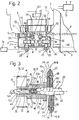
- machine 1 also comprises a box carriage 7 presenting a slide 8 (Figure 2 ⁇ ) fitted in freely-sliding manner to guides 5 so that, by means of an actuating assembly 7a ( Figure 2), carriage 7 is movable along guides 5 to and from an idle position in which slide 8 contacts a limit stop 9 fitted to the end of guides 5 on the opposite side to worktable 4.
- Carriage 7 ( Figure 2) also presents a cutting assembly 10 (described in detail later on) supporting a first and second toolholder body 12 and 14, each fitted integrally with a circular saw 16, 18 as described later on.
- frame 3 presents a clamping device 11 located over worktable 4 and for firmly clamping panel 2 or pack 2a of panels 2 in the cutting position.
- Clamping device 11 presents a bar 15 extending in direction 6 and movable, by means of linear actuators 25 and perpendicularly to surface 4a, to and from a position contacting the top panel 2 in pack 2a on worktable 4.
- Linear actuators 25 are fitted to frame 3 on the opposite side of worktable 4 to guides 5, present respective longitudinal axes substantially perpendicular to surface 4a, and therefore provide for moving bar 15 vertically (i.e. perpendicularly to direction 6) to and from the contacting position, in which they act as thrust members for exerting sufficient downward pressure to clamp panel 2 (or pack 2a of panels 2) in the cutting position.
- Machine 1 comprises a control unit 19 ( Figure 2) which can be controlled by an electronic control unit 13, and which cooperates with cutting assembly 10 to change toolholder bodies 12 and 14, and is described in detail later on.
- Figure 2 which can be controlled by an electronic control unit 13, and which cooperates with cutting assembly 10 to change toolholder bodies 12 and 14, and is described in detail later on.
- Saw 16, 18 presents a central hole by which it is centered on respective body 12, 14, and a number of holes equally spaced about the central hole; and, to support saw 16, 18 integrally, body 12, 14 presents a substantially cylindrical central portion 20 (Figure 3) for the central hole of saw 16, 18, and is defined by two end portions 21 and 22 coaxial with each other and with saw 16, 18. More specifically, whereas portion 22 is substantially cylindrical, portion 21 is conical and presents an integral pin 23 with a mushroom-shaped free end 23a.
- body 12, 14 also presents a flange 24 formed in one piece with body 12, 14 and presenting parallel threaded holes 26 equally spaced about the central axis of symmetry; and an annular body 27 substantially identical to flange 24 and presenting a central hole by which to fit body 27 on to portion 20. More specifically, once fitted on to portion 20, saw 16, 18 is retained in position by body 27 and by screws 28 screwed inside holes 26 to clamp body 27 against flange 24. As such, saw 16, 18 and body 12, 14 form a tool 29 presenting two connecting shanks, a first of which is conical and defined by portion 21, and a second of which is cylindrical and defined by portion 22.
- Portion 22 is essential in the event tool 29 is assembled and disassembled automatically, in which case, portion 22 is gripped between the gripping arms of a gripper forming part of a tool-change device (not shown).
- Cutting assembly 10 comprises a pair of spindles 30 and 31 ( Figures 2, 3), each of which supports a respective body 12, 14, presents a respective horizontal longitudinal axis 32, 33 perpendicular to direction 6, and is fitted in axially-fixed, angularly-free manner to carriage 7.
- spindle 30, 31 comprises a hollow body 34 coaxial with axes 32, 33 and presenting two cylindrical end portions 35 and 36 coaxial with each other and with axes 32, 33. More specifically, portion 36 is substantially a flange and presents a larger outside diameter than portion 35. Body 34 also presents a cylindrical portion 37 coaxial with axes 32, 33, and which is located between and presents an outside diameter between those of portions 35 and 36. Portion 35 is fitted with a gear 38 driven, via a transmission 39, by an electric actuator 40, which therefore rotates both body 34 and spindle 30, 31 about axes 32, 33 ( Figure 2).
- Body 34 presents a longitudinal through cavity 41 coaxial with axes 32, 33, and in turn presenting, at portion 35 and part of portion 37, a cylindrical surface portion 42, and, at the opposite end to portion 35, a conical surface portion 43 housing portion 21 in complementary manner to impart cutting motion to respective saw 16, 18.
- Portion 42 is defined axially by two projections 44 and 45, the second of which separates portions 42 and 43.
- Portion 42 houses in axially-sliding, angularly-fixed manner a tie 46 coaxial with axes 32, 33 and presenting, at the projection 44 end, an annular portion 47, the outside diameter of which is approximately equal to that of portion 42 to guide the tie 46 along portion 42.
- Tie 46 also presents a number of elastic gripping arms 48 equally spaced about axes 32, 33 and defining a gripper 49 for selectively engaging pin 23 and retaining respective end 23a to form a rigid connection between tool 29 and body 34.
- a sleeve 50 (Figure 3) presenting a number of inner grooves 51, each of which acts as a guide for one of elastic gripping arms 48 to control the deformation of arm 48 during axial displacement of tie 46, and to prevent tie 46 from rotating about axes 32, 33.
- Portion 42 also houses, between sleeve 50 and projection 44, a number of Belleville washers 52 for opposing or assisting the movement of tie 46; and tie 46 presents an end portion 53 projecting from portion 35, extending from portion 47, and defined axially by a flat face 54 perpendicular to axes 32, 33.
- Control unit 19 presents two substantially identical linear actuators 56 and 58 ( Figure 2) coaxial with respective spindles 31 and 30.
- Each actuator 56, 58 is operated by a central control unit 60, and presents a rod 61 coaxial with respective axis 33, 32, and which is movable to and from a withdrawn idle position to move respective tie 46, in opposition to washers 52, in such a manner as to open or close gripper 49 to change tool 29.
- Designing the machine to simultaneously receive both saw 16, 18 and toolholder body 12, 14 (i.e. the whole tool 29) by means of a fast-fit connector therefore provides for rapid assembly of one or more sharpened saws.
- the fast-fit connector described also enables tool-change to be effected manually or automatically by means of one or more automatic tool loading and unloading stations.
- Figure 4 shows a larger-scale, more detailed view of the Figure 3 fast-fit connector, of which a number of parts, namely sleeve 50, grooves 51 and Belleville washers 52, have been eliminated for the sake of clarity.
- the top half of Figure 4 shows the situation in which tool 29 has not yet been clamped by gripper 49, and the bottom half the situation in which arms 48 of gripper 49 grip pin 23 and respective end 23a.
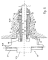
- Figure 5 shows an alternative embodiment of the fast-fit connector in Figure 4.
- Figure 5 which shows a supporting system HSK DIN 69894; OTT-JAKOB), in which the parts common to the previous drawings are indicated using the same numbering system, shows a fast-fit connector in which conical end portion 21, as opposed to being pushed against the conical surface of portion 43 of cavity 41 by pin 23 and end 23a being gripped by gripper 49 and drawn rightwards, is "clamped from the inside" so to speak.
- second expansible bush 63 causes the outer surface of conical end portion 21 to press against conical portion 43 of cavity 41 and the body 12, 14 to press against surface 69 of spindle 30, 31 in order to improve the system stability.
- tool 29 is released from its seat by simply moving tie 46 leftwards (in Figure 5) by means of control unit 19; washers 52 are thus compressed to move first bush 62 leftwards in the Figure 5 embodiment (top half of Figure 5); the leftward movement of bush 62 restores second expansible bush 63 to its initial position, i.e. stop portion 64 disengages shoulder 65 of cavity 66 (top half of Figure 5); and the outer surface of conical end portion 21 is released from conical portion 43 of cavity 41, and body 12, 14 is also released from surface 69 of spindle 30, 31.
- an appropriate automatic system not shown.
- the Figure 5 embodiment also provides for greatly reducing the time required to assemble and remove tool 29 on and off carriage 7.
Landscapes
- Mechanical Engineering (AREA)
- Engineering & Computer Science (AREA)
- Life Sciences & Earth Sciences (AREA)
- Wood Science & Technology (AREA)
- Forests & Forestry (AREA)
- Sawing (AREA)
- Cutting Tools, Boring Holders, And Turrets (AREA)
- Glass Compositions (AREA)
- Processing Of Stones Or Stones Resemblance Materials (AREA)
- Gas-Filled Discharge Tubes (AREA)
- Polishing Bodies And Polishing Tools (AREA)
- Turning (AREA)
- Accessories And Tools For Shearing Machines (AREA)
- Devices For Post-Treatments, Processing, Supply, Discharge, And Other Processes (AREA)
Applications Claiming Priority (2)
| Application Number | Priority Date | Filing Date | Title |
|---|---|---|---|
| ITBO950482 | 1995-10-11 | ||
| IT95BO000482A IT1279651B1 (it) | 1995-10-11 | 1995-10-11 | Macchina sezionatrice di pezzi. |
Publications (1)
| Publication Number | Publication Date |
|---|---|
| EP0768142A1 true EP0768142A1 (en) | 1997-04-16 |
Family
ID=11340851
Family Applications (2)
| Application Number | Title | Priority Date | Filing Date |
|---|---|---|---|
| EP96116276A Withdrawn EP0768142A1 (en) | 1995-10-11 | 1996-10-10 | Panel cutting machine featuring panel pressure clamping devices |
| EP96116275A Expired - Lifetime EP0768143B1 (en) | 1995-10-11 | 1996-10-10 | Panel cutting machine |
Family Applications After (1)
| Application Number | Title | Priority Date | Filing Date |
|---|---|---|---|
| EP96116275A Expired - Lifetime EP0768143B1 (en) | 1995-10-11 | 1996-10-10 | Panel cutting machine |
Country Status (8)
| Country | Link |
|---|---|
| US (2) | US6321629B1 (it) |
| EP (2) | EP0768142A1 (it) |
| AT (1) | ATE216941T1 (it) |
| AU (2) | AU728247B2 (it) |
| CA (2) | CA2187723A1 (it) |
| DE (1) | DE69620970T2 (it) |
| ES (1) | ES2175005T3 (it) |
| IT (1) | IT1279651B1 (it) |
Cited By (3)
| Publication number | Priority date | Publication date | Assignee | Title |
|---|---|---|---|---|
| EP0924037A2 (de) | 1997-12-18 | 1999-06-23 | Michael Weinig Aktiengesellschaft | Kehlmaschine |
| DE10223141A1 (de) * | 2002-05-15 | 2003-11-27 | Reich Spezialmaschinen Gmbh | Bearbeitungsvorrichtung |
| CN109015810A (zh) * | 2018-06-30 | 2018-12-18 | 吴兴铭锯钢琴厂 | 一种钢琴盖板用切割模具 |
Families Citing this family (10)
| Publication number | Priority date | Publication date | Assignee | Title |
|---|---|---|---|---|
| IT1299944B1 (it) * | 1998-03-31 | 2000-04-04 | Giben Impianti Spa | Dispositivo per il taglio di pannelli. |
| DE20311973U1 (de) * | 2003-07-31 | 2003-10-02 | Dienes Werke für Maschinenteile GmbH & Co KG, 51491 Overath | Für einen automatischen Messerwechsel eingerichtete Längsschneidemaschine |
| ITMI20050232U1 (it) * | 2005-06-24 | 2006-12-25 | Busellato S P A | Dispositivo cambia utensili automatico |
| US20070267103A1 (en) * | 2006-05-18 | 2007-11-22 | Unique Machine And Tool Co. | Woodworking machine |
| KR200443078Y1 (ko) * | 2008-04-15 | 2009-01-07 | 유혜경 | 절단위치의 조절이 가능한 절단장치 |
| EP3186042B1 (en) * | 2014-08-29 | 2019-03-06 | Fabio Perini S.p.A. | Method and machine for cutting logs of wound web material |
| CN106426406A (zh) * | 2016-09-21 | 2017-02-22 | 资源县多利士木工机械有限公司 | 一种多通道干料原木多片锯 |
| IT201900022035A1 (it) * | 2019-11-25 | 2021-05-25 | Futura Spa | Macchina per il taglio trasversale dei logs di materiale cartaceo |
| CN111299472A (zh) * | 2020-05-11 | 2020-06-19 | 杭州圣埃蒂机械科技有限公司 | 一种能够自动更换刀片的钢筋切断设备 |
| CN112372699A (zh) * | 2020-11-16 | 2021-02-19 | 东莞市米儿塑胶原料有限公司 | 一种可调式聚氨酯面料切割装置及其使用方法 |
Citations (5)
| Publication number | Priority date | Publication date | Assignee | Title |
|---|---|---|---|---|
| JPS59201714A (ja) * | 1983-04-28 | 1984-11-15 | Mitsubishi Heavy Ind Ltd | サイドトリマの刃替装置 |
| EP0267156A2 (de) * | 1986-11-04 | 1988-05-11 | Fritz Krüsi Maschinenbau | Vorrichtung zum Bearbeiten eines Werkstückes aus Holz, insbesondere von Holzbalken |
| DE8908563U1 (de) * | 1988-08-03 | 1989-09-07 | Fritz Haug AG, St. Gallen | Vorrichtung zum kraftschlüssigen Verbinden eines scheibenförmigen Werkzeuges, insbesondere eines Fräsblattes, mit einer Antriebswelle |
| EP0471197A1 (de) * | 1990-08-15 | 1992-02-19 | Ott Maschinentechnik GmbH i.K. | Spannvorrichtung zum axialen Spannen zweier voneinander lösbarer Maschinenteile |
| EP0539961A1 (en) * | 1991-10-30 | 1993-05-05 | Valenite Inc. | Universal tool connection |
Family Cites Families (24)
| Publication number | Priority date | Publication date | Assignee | Title |
|---|---|---|---|---|
| DE2013403C3 (de) * | 1970-03-20 | 1973-10-31 | Heyligenstaedt & Co, Werkzeugmaschinenfabrik Gmbh, 6300 Giessen | Werkzeugmaschine mit automatischen Werkzeugwechsel |
| US3718061A (en) * | 1970-06-29 | 1973-02-27 | Armstrong Blum Mfg Co | Stop gage for band saw conveyor or the like |
| JPS5148876A (en) * | 1974-10-23 | 1976-04-27 | Toyoda Machine Works Ltd | Jidokogukokansochi |
| DE2540109C3 (de) * | 1975-09-09 | 1978-05-24 | F. Meyer & Schwabedissen Gmbh & Co Kg, 4900 Herford | Kreissäge mit zwei gegenläufig angetriebenen Sägeblättern |
| IT1081442B (it) * | 1977-06-07 | 1985-05-21 | Putsch Meniconi Srl | Testa operatrice per macchina sezionatrice di pannelli specialmente in legno a superficie vista in laminato plastico |
| JPS5771748A (en) * | 1980-10-22 | 1982-05-04 | Toyoda Mach Works Ltd | Automatic tool replacing apparatus |
| JPS5848303A (ja) * | 1981-09-17 | 1983-03-22 | 三菱電機株式会社 | 油入電気機器 |
| DE3326292C1 (de) * | 1983-07-21 | 1985-01-31 | Hans Kaltenbach Maschinenfabrik GmbH & Co, 7850 Lörrach | Vorrichtung zum Wechseln des Sägeblattes an einer Kreissägemaschine |
| DE3750592T2 (de) * | 1986-07-04 | 1995-02-16 | Matsushita Electric Ind Co Ltd | Anordnung zum Auswechseln eines Bestückungskopfes für eine Maschine zum Bestücken von Bauteilen. |
| DE3623555A1 (de) * | 1986-07-12 | 1988-02-04 | Fein C & E | Befestigungseinrichtung fuer scheibenfoermige werkzeuge an der werkzeugspindel einer tragbaren elektrowerkzeugmaschine |
| JPS6348804A (ja) * | 1986-08-19 | 1988-03-01 | 松下電器産業株式会社 | チツプ部品の電極処理装置 |
| DE3716086A1 (de) * | 1987-05-14 | 1988-12-01 | Jenkner Erwin | Vorrichtung zur einstellung von eingriffstiefen eines vorritzsaegeblattes waehrend des vorschubes eines verfahrbaren saegeaggregates |
| DE3741484C1 (de) * | 1987-12-08 | 1989-08-24 | Fein C & E | Handwerkzeugmaschine mit automatischer Arretierung der Arbeitsspindel |
| EP0324357B1 (de) * | 1988-01-09 | 1993-05-19 | C. & E. FEIN GmbH & Co. | Einrichtung zum Spannen eines scheibenförmigen Werkzeugs |
| DE3902874A1 (de) * | 1989-02-01 | 1990-08-09 | Fein C & E | Adapter zum befestigen eines zusatzwerkzeugs |
| US5179883A (en) * | 1990-07-30 | 1993-01-19 | Hans Payr | Apparatus for dividing wood |
| DE59101383D1 (de) * | 1991-01-16 | 1994-05-19 | Fein C & E | Tragbare Schleifmaschine mit Schnellspanneinrichtung. |
| US5159870A (en) * | 1991-08-15 | 1992-11-03 | Fiala Paul E | Portable electric cutting and scoring saw |
| DE9113684U1 (de) * | 1991-11-02 | 1991-12-19 | Keuro Maschinenbau Gmbh & Co Kg, 7590 Achern | Vorrichtung zum Wechseln des Sägeblattes an einer Kreissägemaschine |
| DE9204131U1 (de) * | 1992-03-27 | 1993-07-29 | Schiess-Kopp Werkzeugmaschinen GmbH, 89231 Neu-Ulm | Kettenmagazin zur Aufnahme von Bearbeitungswerkzeugen |
| EP0586759B1 (en) * | 1992-09-09 | 1997-03-05 | Heian Corporation | A panel saw system |
| DE4307482A1 (de) * | 1993-03-10 | 1994-09-22 | Max Rhodius Gmbh | Werkzeugmaschine |
| US5611253A (en) * | 1993-09-07 | 1997-03-18 | Tohoku Ricoh Co., Ltd. | Cutting device |
| JPH0857797A (ja) * | 1994-08-18 | 1996-03-05 | Onishi Raito Kogyosho:Kk | シート材の切断装置 |
-
1995
- 1995-10-11 IT IT95BO000482A patent/IT1279651B1/it active IP Right Grant
-
1996
- 1996-10-10 AT AT96116275T patent/ATE216941T1/de active
- 1996-10-10 EP EP96116276A patent/EP0768142A1/en not_active Withdrawn
- 1996-10-10 EP EP96116275A patent/EP0768143B1/en not_active Expired - Lifetime
- 1996-10-10 ES ES96116275T patent/ES2175005T3/es not_active Expired - Lifetime
- 1996-10-10 AU AU68120/96A patent/AU728247B2/en not_active Ceased
- 1996-10-10 AU AU68119/96A patent/AU719503B2/en not_active Ceased
- 1996-10-10 DE DE69620970T patent/DE69620970T2/de not_active Expired - Lifetime
- 1996-10-11 US US08/730,724 patent/US6321629B1/en not_active Expired - Lifetime
- 1996-10-11 CA CA002187723A patent/CA2187723A1/en not_active Abandoned
- 1996-10-11 US US08/730,723 patent/US5997454A/en not_active Expired - Lifetime
- 1996-10-11 CA CA002187722A patent/CA2187722A1/en not_active Abandoned
Patent Citations (5)
| Publication number | Priority date | Publication date | Assignee | Title |
|---|---|---|---|---|
| JPS59201714A (ja) * | 1983-04-28 | 1984-11-15 | Mitsubishi Heavy Ind Ltd | サイドトリマの刃替装置 |
| EP0267156A2 (de) * | 1986-11-04 | 1988-05-11 | Fritz Krüsi Maschinenbau | Vorrichtung zum Bearbeiten eines Werkstückes aus Holz, insbesondere von Holzbalken |
| DE8908563U1 (de) * | 1988-08-03 | 1989-09-07 | Fritz Haug AG, St. Gallen | Vorrichtung zum kraftschlüssigen Verbinden eines scheibenförmigen Werkzeuges, insbesondere eines Fräsblattes, mit einer Antriebswelle |
| EP0471197A1 (de) * | 1990-08-15 | 1992-02-19 | Ott Maschinentechnik GmbH i.K. | Spannvorrichtung zum axialen Spannen zweier voneinander lösbarer Maschinenteile |
| EP0539961A1 (en) * | 1991-10-30 | 1993-05-05 | Valenite Inc. | Universal tool connection |
Non-Patent Citations (1)
| Title |
|---|
| PATENT ABSTRACTS OF JAPAN vol. 009, no. 070 (M - 367) 30 March 1985 (1985-03-30) * |
Cited By (4)
| Publication number | Priority date | Publication date | Assignee | Title |
|---|---|---|---|---|
| EP0924037A2 (de) | 1997-12-18 | 1999-06-23 | Michael Weinig Aktiengesellschaft | Kehlmaschine |
| EP0924037A3 (de) * | 1997-12-18 | 2004-04-07 | Michael Weinig Aktiengesellschaft | Kehlmaschine |
| DE10223141A1 (de) * | 2002-05-15 | 2003-11-27 | Reich Spezialmaschinen Gmbh | Bearbeitungsvorrichtung |
| CN109015810A (zh) * | 2018-06-30 | 2018-12-18 | 吴兴铭锯钢琴厂 | 一种钢琴盖板用切割模具 |
Also Published As
| Publication number | Publication date |
|---|---|
| IT1279651B1 (it) | 1997-12-16 |
| DE69620970T2 (de) | 2002-11-28 |
| CA2187723A1 (en) | 1997-04-12 |
| ITBO950482A0 (it) | 1995-10-11 |
| DE69620970D1 (de) | 2002-06-06 |
| ITBO950482A1 (it) | 1997-04-11 |
| AU719503B2 (en) | 2000-05-11 |
| ATE216941T1 (de) | 2002-05-15 |
| US5997454A (en) | 1999-12-07 |
| AU6811996A (en) | 1997-04-17 |
| AU6812096A (en) | 1997-04-17 |
| AU728247B2 (en) | 2001-01-04 |
| CA2187722A1 (en) | 1997-04-12 |
| US6321629B1 (en) | 2001-11-27 |
| EP0768143B1 (en) | 2002-05-02 |
| EP0768143A1 (en) | 1997-04-16 |
| ES2175005T3 (es) | 2002-11-16 |
Similar Documents
| Publication | Publication Date | Title |
|---|---|---|
| US6321629B1 (en) | Panel cutting machine featuring panel pressure clamping devices | |
| US6007464A (en) | Tool-changing apparatus and method for a machine tool | |
| US4414732A (en) | Machine tool with automatic tool change function | |
| CN113412175A (zh) | 机床的刀库 | |
| JPH0313950B2 (it) | ||
| KR100978319B1 (ko) | 선반용 자동배출식 척 | |
| JPH09131637A (ja) | アタッチメント及びアタッチメントの割出し方法並びに自動工具交換装置 | |
| CN110052852A (zh) | 保持器及机床 | |
| EP2161101B1 (de) | Vorrichtung zum Spannen eines Werkstücks für die Bearbeitung in einer Schleifmaschine | |
| US4773152A (en) | Automatic tool changer | |
| CN211490644U (zh) | 一种稳定性高的机床夹具 | |
| KR102949779B1 (ko) | 항공기 동체 고정 장치 | |
| JP2701706B2 (ja) | 対向2軸旋盤のカットオフ方法 | |
| CN221066077U (zh) | 一种导向机构及卡套预装模具 | |
| CN218193855U (zh) | 一种数控机床的夹具对准装置 | |
| CN113650444B (zh) | 一种用于消失模雕刻机的快速夹持机构 | |
| KR100212680B1 (ko) | 컴퓨터 수치제어 자동복합선반 | |
| JPH067843Y2 (ja) | 短尺鋼管加工用センタ保持具の自動交換装置 | |
| KR101975208B1 (ko) | 가공장치의 제어방법 | |
| JP2008137145A (ja) | ワークハンド装置およびワークハンド装置の段取りに使用する段取り台、その段取り方法ならびにワークハンド装置を使用したワーク搬送方法 | |
| JPH07314065A (ja) | 複合品の製造方法とその装置 | |
| JPH06126573A (ja) | 回転加工装置 | |
| KR950004809Y1 (ko) | 소형부품 가공기용 자동클램핑장치 | |
| KR200162873Y1 (ko) | Cnc선반의 제품취출용 공구 | |
| JP2723775B2 (ja) | 工作機械の自動工具交換装置 |
Legal Events
| Date | Code | Title | Description |
|---|---|---|---|
| PUAI | Public reference made under article 153(3) epc to a published international application that has entered the european phase |
Free format text: ORIGINAL CODE: 0009012 |
|
| AK | Designated contracting states |
Kind code of ref document: A1 Designated state(s): AT BE DE DK ES FI FR GB IE IT NL SE |
|
| 17P | Request for examination filed |
Effective date: 19971014 |
|
| 17Q | First examination report despatched |
Effective date: 20010330 |
|
| STAA | Information on the status of an ep patent application or granted ep patent |
Free format text: STATUS: THE APPLICATION IS DEEMED TO BE WITHDRAWN |
|
| 18D | Application deemed to be withdrawn |
Effective date: 20010810 |