EP0768269A2 - Dispositif pour le bobinage de plusieurs fils - Google Patents
Dispositif pour le bobinage de plusieurs fils Download PDFInfo
- Publication number
- EP0768269A2 EP0768269A2 EP96203092A EP96203092A EP0768269A2 EP 0768269 A2 EP0768269 A2 EP 0768269A2 EP 96203092 A EP96203092 A EP 96203092A EP 96203092 A EP96203092 A EP 96203092A EP 0768269 A2 EP0768269 A2 EP 0768269A2
- Authority
- EP
- European Patent Office
- Prior art keywords
- yarn
- rotor
- traversing
- blades
- blade
- Prior art date
- Legal status (The legal status is an assumption and is not a legal conclusion. Google has not performed a legal analysis and makes no representation as to the accuracy of the status listed.)
- Granted
Links
- 238000004804 winding Methods 0.000 title description 15
- 230000033001 locomotion Effects 0.000 claims description 6
- 230000007246 mechanism Effects 0.000 abstract description 22
- 238000011144 upstream manufacturing Methods 0.000 abstract description 7
- 238000004519 manufacturing process Methods 0.000 abstract description 4
- 230000009467 reduction Effects 0.000 abstract description 4
- 238000012546 transfer Methods 0.000 description 18
- 238000005452 bending Methods 0.000 description 17
- 238000000034 method Methods 0.000 description 5
- 238000012423 maintenance Methods 0.000 description 3
- 230000015572 biosynthetic process Effects 0.000 description 2
- 238000009826 distribution Methods 0.000 description 2
- 230000008569 process Effects 0.000 description 2
- 230000001105 regulatory effect Effects 0.000 description 2
- 230000008859 change Effects 0.000 description 1
- 230000006866 deterioration Effects 0.000 description 1
- 238000011161 development Methods 0.000 description 1
- 230000000694 effects Effects 0.000 description 1
- 230000003028 elevating effect Effects 0.000 description 1
- 230000000977 initiatory effect Effects 0.000 description 1
- 239000000203 mixture Substances 0.000 description 1
- 230000004048 modification Effects 0.000 description 1
- 238000012986 modification Methods 0.000 description 1
- 229920000728 polyester Polymers 0.000 description 1
- 238000009987 spinning Methods 0.000 description 1
- 230000001360 synchronised effect Effects 0.000 description 1
Images






Classifications
-
- B—PERFORMING OPERATIONS; TRANSPORTING
- B65—CONVEYING; PACKING; STORING; HANDLING THIN OR FILAMENTARY MATERIAL
- B65H—HANDLING THIN OR FILAMENTARY MATERIAL, e.g. SHEETS, WEBS, CABLES
- B65H54/00—Winding, coiling, or depositing filamentary material
- B65H54/02—Winding and traversing material on to reels, bobbins, tubes, or like package cores or formers
- B65H54/28—Traversing devices; Package-shaping arrangements
- B65H54/2836—Traversing devices; Package-shaping arrangements with a rotating guide for traversing the yarn
- B65H54/2839—Traversing devices; Package-shaping arrangements with a rotating guide for traversing the yarn counter rotating guides, e.g. wings
-
- B—PERFORMING OPERATIONS; TRANSPORTING
- B65—CONVEYING; PACKING; STORING; HANDLING THIN OR FILAMENTARY MATERIAL
- B65H—HANDLING THIN OR FILAMENTARY MATERIAL, e.g. SHEETS, WEBS, CABLES
- B65H54/00—Winding, coiling, or depositing filamentary material
- B65H54/02—Winding and traversing material on to reels, bobbins, tubes, or like package cores or formers
- B65H54/38—Arrangements for preventing ribbon winding ; Arrangements for preventing irregular edge forming, e.g. edge raising or yarn falling from the edge
- B65H54/381—Preventing ribbon winding in a precision winding apparatus, i.e. with a constant ratio between the rotational speed of the bobbin spindle and the rotational speed of the traversing device driving shaft
-
- B—PERFORMING OPERATIONS; TRANSPORTING
- B65—CONVEYING; PACKING; STORING; HANDLING THIN OR FILAMENTARY MATERIAL
- B65H—HANDLING THIN OR FILAMENTARY MATERIAL, e.g. SHEETS, WEBS, CABLES
- B65H2701/00—Handled material; Storage means
- B65H2701/30—Handled filamentary material
- B65H2701/31—Textiles threads or artificial strands of filaments
Definitions
- the present invention relates to an apparatus, for winding a plurality of yarns, having a traverse-motion mechanism in which a plurality of traversing units are provided each reciprocating a yarn by means of a plurality of blades secured to a pair of rotors.
- the yarn winder comprises a spindle rotatably carried on a machine frame for carrying bobbins and a traverse-motion mechanism mounted on the machine frame above the spindle while being movable upward and downward or a turret type yarn winder in which a plurality of spindles for carrying bobbins are rotatably carried on a turret member which, in turn, is rotatably mounted on a machine frame.
- a traverse-motion mechanism used for a high-speed winder comprises a plurality of traversing units, each consisting of a pair of rotors carried on a frame at a distance from each other, a plurality of blades secured onto the respective rotor, and a yarn guide fixed to the frame so as to be located in the path of a yarn-guiding edge of the blade.
- the traversing units are arranged at a predetermined pitch in the lengthwise direction of the bobbin-carrying spindle, while a touch roller is rotatably carried on the frame close to the blade of the respective traverse unit at a position downstream thereof.
- the blades are positioned around the rotor at an angular pitch of 180° and 120° when the number of blades is two and three, respectively.
- a pair of rotors, each provided with the same number of blades, are secured on the frame at a distance therebetween and rotatable in the reverse direction to each other.
- a traverse-motion mechanism having a plurality of such traversing units is disclosed, for example, in Japanese Examined Patent Publication Nos. 3-72544 (corresponding to the U.S. Patent No. 4505436) and 4-27151 (corresponding to the U.S. Patent No. 4505437).
- the lengthening of spindle causes the increase of a yarn bending angle at a yarn-separating fulcrum directly beneath a godet roller on the upstream side toward a yarn-traversing fulcrum positioned at the respective end of the spindle, which, in turn, results in the deterioration of yarn quality due to the increase of running resistance at the fulcrum.
- the yarn is taken up by a higher winding tension, a yarn package thus obtained is difficult to unwind.
- a gap of about 25 mm is sufficient between the adjacent full packages for manipulating them.
- the each of them must be adapted to intermesh with a common intermediate gear through a gear fixed with the respective rotor so that one rotor is rotatable when the other rotor is driven by a common driving mechanism.
- a yarn package taken up via the abovesaid traverse-motion mechanism has the drawback of an increase in package selvage and ribbon wind because the turning points of the traversing stroke and a running trace of yarn are constant from the initiation to the completion of the package formation.
- a method for providing a plurality of turning points and running traces of yarn, by using a rotor with blade, each having a yarn-guiding edge different from the other (which is called a "selvage-rise flattening method").
- Such a traverse-motion mechanism for providing a plurality of turning points is described, for example, in Japanese Examined Patent Publication (Kokoku) No. 49-2394.
- the method adopting such the blades, each having a different shape from the other, has drawbacks in that the number of turning points is at most equal to that of blades, a stepped selvage is liable to occur when the number of turning points is as few as two or three, and the traverse-motion mechanism becomes too large to put into practice when as many as six through eight blades are used to minimize the rise of selvage.
- the first problem to be solved by the present invention is the difficulty of the threading operation due to the increase of distance of yarn-separating fulcrum or godet roller from a yarn-traversing fulcrum disposed downstream thereof.
- a second problem is that the winder becomes too large to be installed in a building except for one having a particularly high ceiling.
- a third problem is that, since the pitch of traversing units cannot be shortened, unfavorably longer bobbins and spindles must be used.
- a fourth problem is that, since the distance between axes of the adjacent rotors is very small in a traverse-motion mechanism having a pair of rotors, each provided with the same number of blades, such as two or three, it is necessary to provide a part such as an intermediate gear for driving one rotor by the other rotor, which increases the complexity of the structure and results in an increase in time for the production of parts, and assembly and maintenance thereof.
- a fifth problem is that the number of turn points is at most three even if each of three blends has a yarn-guiding edge with a different shape from the other, whereby it is impossible to minimize the rise of package selvage and the ribbon wind to an extent not influencing the package quality.
- a sixth problem is that a turning point cannot be changed unless a blade is replaced with a new one.
- an apparatus for winding a plurality of yarn-according to the present invention in which a traversing unit disposed at least one end of the apparatus is offset in a plane intersecting the yarn running direction at a position where a yarn is in contact with a traverse quiding element so that a line connecting the opposite ends of a traversing zone in the traversing unit is not parallel to an axis of a touch roller.
- a traversing unit comprises a first rotor with m blades and a second rotor with n blades (n ⁇ m), wherein any adjacent two such traversing units are symmetrically arranged relative to an axis vertical to the yarn traversing direction and the first and second rotors in one traversing unit rotate in reverse to the rotors in the other traversing unit, and wherein axes of the first and second rotors in one traversing unit are distant from each other in the direction generally vertical to an axis of a bobbin-carrying spindle.
- a traversing unit preferably comprises a pair of rotors rotatably secured on a frame, a plurality of blades attached on the respective rotors, and a yarn guiding element attached to the frame along a rotary path of the blades.
- a traversing unit has m blades on the first and n blades on the second rotor (m ⁇ n) arranged at equi-angular positions on a rotary circle thereof, and the rotational centers of the first and second rotors are defined so that a rotary angle is about 360°/2m in the first rotor and about 360°/2n in the second rotor, which angle is passed by a blade of one rotor when it displaces a yarn running while being in contact therewith along the yarn guiding element until the yarn is transferred to a blade of the other rotor, and in which a rotational ratio between the first and second rotors is defined to be n:m.
- a traversing unit has m blades on the first rotor and n blades on the second rotor (m ⁇ n) and yarn-guiding edges formed on distal ends of the respective blades are arranged at positions different from and offset from equiangular positions on a circle in a rotary plane.
- a traversing unit is adapted to be capable of adjusting a mounting position of blades with reference to quiding portions formed on the first and second rotors.
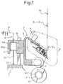
- the winding apparatus includes a bobbin-carrying spindle 2 rotatably secured onto a machine frame 1 in a horizontal position and a traverse-motion mechanism 3 disposed above the spindle 2 and carried on a guiding pillar 1a attached on the machine frame 1 while being movable upward and downward.
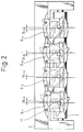
- Yarn-traversing fulcrums 35-1 through 35-4 and a yarn-separating fulcrum 36 are provided above the traverse-motion mechanism 3.
- the traverse-motion mechanism 3 includes a slider 4 movable upward and downward while being engaged with the guiding pillar 1a provided on the machine frame 1, a frame body 5 fixed to the slider 4 and extending above and parallel to a spindle 2 rotatably secured on the machine frame 1 in a horizontal position, a plurality of traversing units 6-1 through 6-4 arranged on the frame body 5 in the longitudinal direction of the spindle 2 at a pitch between every adjacent units, a plurality of touch rollers 7 rotatably attached to the frame body 5 in parallel to the spindle 2, a contact pressure mechanism 8 for applying a predetermined pressure to a bobbin 40 or a package 50 carried on the spindle 2, and a drive mechanism 9 for rotating the traversing units 6-1 through 6-4.
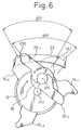
- each of the abovesaid traversing units 6-1 through 6-4 includes a support 10 fixed to the frame body 5 by a screw 11, a first rotor 13 rotatably secured, via a bearing 14, to a shaft 12 projected from the support 10, a plurality of blades 15-1 through 15-3 fixed by screws 16 to the first rotor 13, while being engaged with a circular recess 13a formed thereon, at about 120° angular pitch therebetween as seen in a rotary plane, a second rotor 18 rotatably secured, via a bearing 19, to a support 17 fixed to the distal end of the shaft 12, a plurality of blades 20-1 and 20-2 fixed by screws 21 to the second rotor 18, while abutting a circular protrusion 18a formed thereon, at about 180° angular pitch therebetween as seen in a rotary plane, a gear 22 integrally mounted to a distal end of the second rotor 18 to be meshed with a gear 13b formed at one end of the first
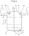
- An arcuate stepped portion 5a is formed on the frame body 5, having a center at a middle point C between the opposite ends A and B of a yarn-traversing path on the yarn-guiding surface 23, on which the yarn repeats the traverse motion while being in contact therewith. Also an arcuate terminal portion 10a is provided on the support 10 to be brought into surface contact with the arcuate stepped portion 5a formed on the frame body 5. In this regard, openings 10b for setting the screws 11 have an elongated shape.
- the rotor 13 rotates in the reverse direction to the rotor 18, and the shape of the respective blade 15-1 through 15-3 and that of the respective blade 20-1 and 20-2 in one traversing unit are symmetrical to those of the other.
- the contact pressure mechanism 8 consist of a piston 25 having a head 25a movably fitted in an air chamber 4a formed in the slider 4 and a lower end attached to the machine frame 1 via a bracket 26, and a compressed air supply conduit 27 connected with the air chamber 4a of the slider 4 and having a pressure regulating valve, an electromagnetic selector valve or other.
- the touch roller 7 attached to the frame body 5 together with the slider 4 is elevated to reduce the contact pressure against the spindle 2, and, on the contrary, when low pressure air is supplied, the elevating force is reduced to increase the contact pressure.
- the drive mechanism 9 consists of a motor 28 mounted onto the frame body 5, a toothed pulley 29 attached to an output shaft 28a of the motor 28, and a toothed belt 30 wrapped around a toothed pulley 13c fixed on the first rotor 13 of each of the traversing units 6-1 through 6-4.
- the second rotor 18 is made to rotate via a gear 13b of the first rotor 13 and the gear 22.
- a position of point P is defined so that a rotary angle of the blade 20-1 or 20-2 is 90 from a first yarn-transfer position A to a second yarn-transfer position B when the blades 20-1 and 20-2 are attached to the second rotor 18 at an angular pitch of 180° as seen in a rotary plane thereof, i.e., in a point-symmetrical manner having a center at point P and the blades 15-1 through 15-3 are attached to the first rotor 12 at an angular pitch of 120° as seen in a rotary plane thereof.
- positions of a point R and the yarn-guiding surface 23 are defined so that a rotary angle of the blade 15-1 or 15-3 from the second yarn-transfer position B to the first yarn-transfer position A is 60°.
- the point P is a rotary center of the second rotor 18 and the point R is a rotary center of the first rotor 13.
- the numbers of the gear 13a formed on the first rotor 13 and of the gear 22 fixed to the second rotor 18 are decided so that a rotational ratio between the first rotor 13 and the second rotor 18 becomes 2:3, and the positions of teeth in the gear 13b of the first rotor 13 and the gear 22 of the second rotor 18 are decided so that each of the blades 15-1 through 15-3 intersects the blade 20-1 or 20-2 at the respective yarn-transfer positions A and B.
- the blade 15-3 is moved clockwise to reduce the angle between the blades 15-1 and 15-3 to be less than 120° and fixed to the first rotor 13, while the blade 15-2 is moved counterclockwise to reduce the angle between the blades 15-1 and 15-2 to be less than 120° and fixed to the first rotor 13. Also the blades 20-1 and 20-2 are moved counterclockwise and clockwise, respectively, from the abovesaid positions and fixed to the second rotor 18.
- the blades 15-1 through 15-3 are positioned as follows; first a line RE connecting a point R in Fig. 7 with a point E on a yarn-guiding edge formed at a distal end of the blade 15-1 is defined as a reference line, then the blade 15-3 is rotated clockwise to touch a line RF' offset through ⁇ -1 from a line RF offset counterclockwise through 120° from the line RE and fixed while the blade 15-2 is rotated to touch a line RG' offset counterclockwise through ⁇ -2 from a line RG offset clockwise through 120° from the line RE and fixed.
- the blades 20-1 and 20-2 are positioned as follows; first the line RE described above with reference to the blade 15-1 is defined as a reference line, then a point S is determined on a yarn-guiding edge formed at a distal end of the blade 20-1 when the blade 15-1 intersects the blade 20-1 at the yarn-transfer position A on the yarn-guiding surface 23 while maintaining a meshing state of the gear 13b of the first rotor 13 with the gear 22 of the second rotor 18, and a point T is determined on a yarn-guiding edge formed at a distal end of the blade 20-2 offset 180° from the point S.
- a line STP connecting the point S with the point T is defined as another reference line, and the blade 20-2 is rotated to touch a line PT' offset clockwise through ⁇ -4 from the line STP and fixed, while the blade 20-1 is rotated to touch a line PS' offset counterclockwise through ⁇ -3 therefrom and fixed.
- angles ⁇ -1 through ⁇ -4 may vary in accordance with yarn thickness, yarn kinds, yarn winding speed or others, distances between the points F,F'; G,G'; S,S'; and T,T' are preferably in a range of 0.5 mm through 3 mm.
- the yarn is subsequently transferred from the blade 15-3 to the blade 20-2 at the yarn-transfer position A, from the blade 20-2 to the blade 15-2 at the position B, from the blade 15-2 to the blade 20-1 at the position A, from the blade 20-1 to the blade 15-1 at the position B, from the blade 15-1 to the blade 20-2 at the position A, from the blade 20-2 to the blade 15-3 at the position B, from the blade 15-3 to the blade 20-1 at the position A, from the blade 20-1 to the blade 15-2 at the position B, from the blade 15-2 to the blade 20-2 at the position A, and from the blade 20-2 to the blade 15-1 at the position B; thus the yarn returns to the initial state.
- the yarn is subjected to a traverse motion on the yarn-guiding surface 23 by the subsequent transfers between the three blades 15-1 through 15-3 and the two blades 20-1 and 20-2.
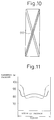
- Fig. 8 illustrates the movement of the traversing yarn by the respective blades stated above, in which the ordinate represents a time passage and the abscissa represents a yarn position relative to a package width A through B.
- the relationship between the time passage and the yarn position is one represented by a solid line, in which it is apparent that the turning points vary in a synchronized manner, compared to a case when no offsets exist, as represented by a dotted line.
- a distance between the rotational center R of the first rotor 13 and that P of the second rotor 18 becomes about one third of the traversing stroke. Accordingly, assuming the traverse stroke is 123 mm, a distance between axes of first and second rotors 13, 18 is about 42 mm; and assuming the traversing stroke is 85 mm, the distance between the axes is about 30 mm, which means that the rotation can be transmitted between both the rotors by the direct intermeshing of gears provided on the respective rotors.
- Fig. 11 shows hardness distributions measured by a hardness tester of JIS A type in two packages of polyester yarn (75 denier/36 filaments) formed by the abovesaid traverse-motion mechanism under the conditions of a traversing stroke of 123 mm, a winding angle of 5.7°, a winding speed of 3100 m/min, and a final package diameter of 420 mm; one being wound with the blades at regular positions and the other being wound with the blades offset about 1 mm from the former. It is apparent from the results that, when the blades are offset from the regular positions (represented by a solid line), a difference of hardness is less than that when the blades are at the regular positions (represented by a chain line).
- a selvage rise ( ⁇ ) and a lateral bulge ( ⁇ ) are listed in Table 1, both of which are minimized when the blades are offset.
- the numbers of blades provided on the first and second rotors 13, 18 are prefearbly a combination of odd and even numbers, respectively, such as two and three or three and four, so that more turning points can be obtained using fewer blades.
- This pitch L between the adjacent traversing units is 5.5% shorter than that in the conventional traversing units shown in Fig. 14.
- a yarn bending angle ⁇ -15 made by the traverse end position B, the position J of the yarn-traversing fulcrum 35-1 and the position K of the yarn-separating fulcrum 36 is prefearbly about 20° to not increase a resistance against the running yarn and to prevent the fluctuation of a yarn tension from occurring in the upstream region.
- the position K of the yarn-separating fulcrum 36 is decided so that the yarn bending angle ⁇ -15 made by the traverse end position B of the traversing unit 6-1, the position J of the yarn-traversing fulcrum 35-1 and the position K of the yarn-separating fulcrum 31 is 20° and the yarn bending angle ⁇ -15 made by the traverse end position A of the traversing unit 6-4, the position J of the yarn-traversing fulcrum 35-4 and the position K of the yarn-separating fulcrum 36 is 20°.
- the traversing units 6-1 and 6-2 are made to offset clockwise through ⁇ -11 and ⁇ -12, respectively, in a plane shown in Fig. 2 substantially vertical to the running yarn at a position where the yarn is in contact with the traverse guide, and the traversing units 6-3 and 6-4 are made to offset counterclockwise, i.e., in the reverse direction to the traversing units 6-1 and 6-2, through ⁇ -13 and ⁇ -14, respectively.
- the above positioning operation of traversing units is carried out by sliding the respective support 10 along the arcuate stepped portion 5a formed on the frame body 5 and fixing the same on the frame body 5 by the screws 11.
- a position J' of the yarn-traversing fulcrum 35-1 is decided at first so that a length of a yarn path J'-A-M becomes equal to a length of a yarn path J'-B-M.
- a position K2 of the yarn-separating fulcrum 36 is decided so that a sum of yarn bending angles ⁇ -17 and ⁇ -18 made by the position B of the traverse end, the position J' of the yarn-traversing fulcrum 35-1 and the position K of the yarn-separating fulcrum 36 is equal to a sum of the yarn bending angles ⁇ -15 and ⁇ -16.
- the position K2 of the yarn-separating fulcrum 36 when the traversing unit 6-1 is offset clockwise as described above, is H mm lower than the position K of the yarn-separating fulcrum when the traversing unit 6-1 is not offset.
- the number of traversing units is eight, the traversing stroke is 123 mm, the pitch between the adjacent traversing units is 153 mm and the offset angles ⁇ -11 and ⁇ -14 of the traversing units 6-1 and 6-4, respectively, are 2.5°, it is possible to shift the positions J' of the yarn-traversing fulcrums 35-1 and 35-4 12 mm closer to the center, and if the yarn bending angle ⁇ -19 at the yarn-traversing fulcrum 35-1 or 35-4 is 20°, a height distance between the position J' of the yarn-traversing fulcrum 35-1 or 35-4 and the position K3 of the yarn-separating fulcrum 36 becomes 2390 mm, which is 490 mm lower than the distance 2880 mm in the conventional case when the traversing unit is not offset.
- the traversing unit provided at one of opposite ends thereof is offset in a plane intersecting the yarn running while being in contact with the traverse guiding element, so that a straight line connecting the opposite ends of the traversing zone is not parallel to an axis of the touch roller, a traversing center of the yarn-guiding surface can be displaced closer to another traversing unit disposed on the other side.
- the traverse-motion mechanism is formed so that m blades (m ⁇ n) are attached to the first rotor, one traversing unit is symmetrical to the adjacent one relative to an axis vertical to the traverse direction, the first and second rotors in one traversing unit respectively rotate in reverse to those in the adjacent traversing unit, and an axis of the first rotor is distant from an axis of the second rotor in the direction substantially vertical to an axis of the bobbin carrying spindle, it is possible for any one package to be necessarily and sufficiently closer to the adjacent package to avoid the use of the unnecessarily longer bobbin and spindle.
- the traversing unit is formed by a pair of rotors rotatably carried on a frame body, a plurality of blades fixed to the respective rotor and a yarn-guiding surface attached onto the frame body to conform with the rotary path of the blades, is possible to make the overall structure thereof in a simple manner.
- the traversing unit is formed so that the numbers of blades attached to the first and second rotors are m and n (m ⁇ n), respectively, and a rotational ratio of the first rotor relative to the second rotor is n:m; the blades being arranged in an equiangular manner on the respective circle depicted in a rotary plane thereof while positioning the rotary centers of the first and second rotors so that the rotary angle, through which one blade on the one rotor guides the yarn along the yarn-guiding surface to transfer the same to another blade on the other rotor, is about 360°/2m in the first rotor and about 360°/2n in the second rotor; it is possible to increase the interaxial distance between the first and second rotors and to drive the respective rotor directly by the other rotor without providing an intermediate gear or the like, resulting in a simple structure and there reduction of time required for the parts-manufacturing operation, assembling operation and maintenance operation.
- the traversing unit according to the present invention is formed so that the numbers of blades attached to the first and second rotors are m and n (m ⁇ n), respectively and the blades are arranged on the respective rotor so that the yarn-guiding edge provided at a distal end of the blade is offset from the equiangularly-divided position on the respective circle depicted in a rotary plane thereof, it is possible to obtain more than six yarn turning points and minimizing the rise of package selvage and the generation of ribbon wind so that the product quality is not influenced thereby.
Landscapes
- Engineering & Computer Science (AREA)
- Textile Engineering (AREA)
- Winding Filamentary Materials (AREA)
Applications Claiming Priority (7)
| Application Number | Priority Date | Filing Date | Title |
|---|---|---|---|
| JP24424092 | 1992-08-19 | ||
| JP4244240A JP2530545B2 (ja) | 1992-08-19 | 1992-08-19 | トラバ―ス装置 |
| JP244240/92 | 1992-08-19 | ||
| JP297885/92 | 1992-10-09 | ||
| JP29788592 | 1992-10-09 | ||
| JP4297885A JP2678417B2 (ja) | 1992-10-09 | 1992-10-09 | 多糸条巻取機 |
| EP94908105A EP0612683B1 (fr) | 1992-08-19 | 1993-08-19 | Machine d'enroulement de fils multiples |
Related Parent Applications (2)
| Application Number | Title | Priority Date | Filing Date |
|---|---|---|---|
| EP94908105A Division EP0612683B1 (fr) | 1992-08-19 | 1993-08-19 | Machine d'enroulement de fils multiples |
| EP94908105.3 Division | 1994-03-03 |
Publications (3)
| Publication Number | Publication Date |
|---|---|
| EP0768269A2 true EP0768269A2 (fr) | 1997-04-16 |
| EP0768269A3 EP0768269A3 (fr) | 1997-07-30 |
| EP0768269B1 EP0768269B1 (fr) | 1999-06-09 |
Family
ID=26536636
Family Applications (2)
| Application Number | Title | Priority Date | Filing Date |
|---|---|---|---|
| EP96203092A Expired - Lifetime EP0768269B1 (fr) | 1992-08-19 | 1993-08-19 | Dispositif pour le bobinage de plusieurs fils |
| EP94908105A Expired - Lifetime EP0612683B1 (fr) | 1992-08-19 | 1993-08-19 | Machine d'enroulement de fils multiples |
Family Applications After (1)
| Application Number | Title | Priority Date | Filing Date |
|---|---|---|---|
| EP94908105A Expired - Lifetime EP0612683B1 (fr) | 1992-08-19 | 1993-08-19 | Machine d'enroulement de fils multiples |
Country Status (4)
| Country | Link |
|---|---|
| US (1) | US5566905A (fr) |
| EP (2) | EP0768269B1 (fr) |
| DE (2) | DE69325292T2 (fr) |
| WO (1) | WO1994004452A1 (fr) |
Cited By (1)
| Publication number | Priority date | Publication date | Assignee | Title |
|---|---|---|---|---|
| CN102219133A (zh) * | 2011-04-11 | 2011-10-19 | 丝丝姆纺织机械(中山)有限公司 | 一种络筒机拨片式排线装置 |
Families Citing this family (3)
| Publication number | Priority date | Publication date | Assignee | Title |
|---|---|---|---|---|
| DE4425133C2 (de) * | 1994-07-15 | 1997-03-13 | Neumag Gmbh | Aufspulmaschine |
| DE29503084U1 (de) * | 1995-02-24 | 1995-04-27 | Neumag - Neumünstersche Maschinen- und Anlagenbau GmbH, 24536 Neumünster | Changiervorrichtung |
| RU2141443C1 (ru) * | 1998-10-19 | 1999-11-20 | Безденежных Алла Германовна | Устройство для раскладки нити на паковку |
Citations (3)
| Publication number | Priority date | Publication date | Assignee | Title |
|---|---|---|---|---|
| JPS492394B1 (fr) | 1970-06-05 | 1974-01-19 | ||
| JPH0372544B2 (fr) | 1983-01-19 | 1991-11-19 | Barmag Barmer Maschf | |
| JPH0427151B2 (fr) | 1983-01-29 | 1992-05-11 | Barmag Barmer Maschf |
Family Cites Families (15)
| Publication number | Priority date | Publication date | Assignee | Title |
|---|---|---|---|---|
| US4230284A (en) * | 1979-07-11 | 1980-10-28 | Owens-Corning Fiberglas Corporation | Method and apparatus for collecting strands |
| US4300728A (en) * | 1980-05-29 | 1981-11-17 | Owens-Corning Fiberglas Corporation | Apparatus for packaging strand |
| JPS5781066A (en) * | 1980-11-07 | 1982-05-20 | Toray Ind Inc | Taking-up of yarn |
| JPS5948357A (ja) * | 1982-09-08 | 1984-03-19 | Toray Ind Inc | 糸条巻取方法およびその装置 |
| US4505436A (en) * | 1983-01-19 | 1985-03-19 | Barmag Barmer Maschinenfabrik Ag | Yarn winding apparatus |
| EP0114641B1 (fr) * | 1983-01-19 | 1986-05-28 | b a r m a g Barmer Maschinenfabrik Aktiengesellschaft | Machine à bobiner avec guide-fil à pales |
| US4505437A (en) * | 1983-01-29 | 1985-03-19 | Barmag Barmer Maschinenfabrik Ag | Apparatus for winding a plurality of yarns |
| DE3345237A1 (de) * | 1983-12-14 | 1985-06-27 | Barmag Barmer Maschinenfabrik Ag, 5630 Remscheid | Aufspulmaschine |
| EP0194648B1 (fr) * | 1985-03-15 | 1989-06-28 | B a r m a g AG | Machine à bobiner |
| DE3614831A1 (de) * | 1985-05-10 | 1986-11-13 | Barmag Barmer Maschinenfabrik Ag, 5630 Remscheid | Aufspulmaschine |
| CH669175A5 (de) * | 1985-05-10 | 1989-02-28 | Barmag Barmer Maschf | Aufspulmaschine. |
| DE3826130A1 (de) * | 1987-08-05 | 1989-02-23 | Barmag Barmer Maschf | Verfahren zur stabilisierung der wickelendbereiche |
| US4991783A (en) * | 1987-12-30 | 1991-02-12 | Teijin Seiki Co., Ltd. | Yarn traversing method and an apparatus therefor |
| US5308004A (en) * | 1988-09-06 | 1994-05-03 | Asahi Kasei Kogyo Kabushiki Kaisha | Method of automatically transferring an elastic yarn from a full-bobbin to an empty-bobbin |
| JP2560918B2 (ja) * | 1990-12-28 | 1996-12-04 | 村田機械株式会社 | トラバース装置 |
-
1993
- 1993-08-19 DE DE69325292T patent/DE69325292T2/de not_active Expired - Fee Related
- 1993-08-19 US US08/211,671 patent/US5566905A/en not_active Expired - Fee Related
- 1993-08-19 WO PCT/JP1993/001163 patent/WO1994004452A1/fr not_active Ceased
- 1993-08-19 EP EP96203092A patent/EP0768269B1/fr not_active Expired - Lifetime
- 1993-08-19 DE DE69317108T patent/DE69317108T2/de not_active Expired - Fee Related
- 1993-08-19 EP EP94908105A patent/EP0612683B1/fr not_active Expired - Lifetime
Patent Citations (3)
| Publication number | Priority date | Publication date | Assignee | Title |
|---|---|---|---|---|
| JPS492394B1 (fr) | 1970-06-05 | 1974-01-19 | ||
| JPH0372544B2 (fr) | 1983-01-19 | 1991-11-19 | Barmag Barmer Maschf | |
| JPH0427151B2 (fr) | 1983-01-29 | 1992-05-11 | Barmag Barmer Maschf |
Cited By (1)
| Publication number | Priority date | Publication date | Assignee | Title |
|---|---|---|---|---|
| CN102219133A (zh) * | 2011-04-11 | 2011-10-19 | 丝丝姆纺织机械(中山)有限公司 | 一种络筒机拨片式排线装置 |
Also Published As
| Publication number | Publication date |
|---|---|
| WO1994004452A1 (fr) | 1994-03-03 |
| DE69325292D1 (de) | 1999-07-15 |
| EP0768269A3 (fr) | 1997-07-30 |
| EP0612683B1 (fr) | 1998-02-25 |
| EP0612683A4 (fr) | 1995-01-25 |
| DE69325292T2 (de) | 1999-09-30 |
| DE69317108T2 (de) | 1998-06-25 |
| EP0768269B1 (fr) | 1999-06-09 |
| EP0612683A1 (fr) | 1994-08-31 |
| US5566905A (en) | 1996-10-22 |
| DE69317108D1 (de) | 1998-04-02 |
Similar Documents
| Publication | Publication Date | Title |
|---|---|---|
| US4505436A (en) | Yarn winding apparatus | |
| US3861607A (en) | High-speed cross-winding device | |
| KR100539034B1 (ko) | 합성 필라멘트용 권사기 | |
| US5566905A (en) | Apparatus for winding a plurality of yarns | |
| US4911370A (en) | Method and apparatus for winding yarn | |
| US3718288A (en) | Yarn package | |
| EP0322752B1 (fr) | Procédé et dispositif pour l'empaquetage de fil | |
| US5277668A (en) | Gear transmissions, for textile machines | |
| US20090134263A1 (en) | Method for Avoiding Ribbon Windings | |
| CN1031933C (zh) | 络纱机 | |
| US6895736B2 (en) | Thread-guiding device for collecting spun yarns on bobbins particularly for open-end spinning frames | |
| CA1101395A (fr) | Traduction non-disponible | |
| JP2530545B2 (ja) | トラバ―ス装置 | |
| US5149002A (en) | Yarn traversing apparatus | |
| EP0834462B1 (fr) | Dispositif de bobinage | |
| JPS62140976A (ja) | 糸巻取装置 | |
| KR100457402B1 (ko) | 와인더의 트레버스 구동장치 | |
| EP3894618B1 (fr) | Ourdissoir pour une corde, machine à fabriquer des cordes et utilisation correspondante | |
| KR100838007B1 (ko) | 탄성 섬유용 와인더 | |
| JP2780336B2 (ja) | 糸条の巻取体製造装置 | |
| JPH0372544B2 (fr) | ||
| JP2756831B2 (ja) | 精密巻取機 | |
| EP0151836B1 (fr) | Enroulement de fil de filament en carbone et procédé pour l'obtention d'un tel enroulement | |
| JP2618038B2 (ja) | 糸条のトラバース装置 | |
| SU1348283A1 (ru) | Устройство дл укладки нитевидного материала |
Legal Events
| Date | Code | Title | Description |
|---|---|---|---|
| PUAI | Public reference made under article 153(3) epc to a published international application that has entered the european phase |
Free format text: ORIGINAL CODE: 0009012 |
|
| AC | Divisional application: reference to earlier application |
Ref document number: 612683 Country of ref document: EP |
|
| AK | Designated contracting states |
Kind code of ref document: A2 Designated state(s): CH DE LI |
|
| PUAL | Search report despatched |
Free format text: ORIGINAL CODE: 0009013 |
|
| AK | Designated contracting states |
Kind code of ref document: A3 Designated state(s): CH DE GB IT LI |
|
| 17P | Request for examination filed |
Effective date: 19971229 |
|
| GRAG | Despatch of communication of intention to grant |
Free format text: ORIGINAL CODE: EPIDOS AGRA |
|
| 17Q | First examination report despatched |
Effective date: 19981020 |
|
| GRAG | Despatch of communication of intention to grant |
Free format text: ORIGINAL CODE: EPIDOS AGRA |
|
| GRAH | Despatch of communication of intention to grant a patent |
Free format text: ORIGINAL CODE: EPIDOS IGRA |
|
| GRAH | Despatch of communication of intention to grant a patent |
Free format text: ORIGINAL CODE: EPIDOS IGRA |
|
| RBV | Designated contracting states (corrected) |
Designated state(s): CH DE LI |
|
| GRAA | (expected) grant |
Free format text: ORIGINAL CODE: 0009210 |
|
| AC | Divisional application: reference to earlier application |
Ref document number: 612683 Country of ref document: EP |
|
| AK | Designated contracting states |
Kind code of ref document: B1 Designated state(s): CH DE LI |
|
| REG | Reference to a national code |
Ref country code: CH Ref legal event code: NV Representative=s name: E. BLUM & CO. PATENTANWAELTE Ref country code: CH Ref legal event code: EP |
|
| REF | Corresponds to: |
Ref document number: 69325292 Country of ref document: DE Date of ref document: 19990715 |
|
| PGFP | Annual fee paid to national office [announced via postgrant information from national office to epo] |
Ref country code: CH Payment date: 19990720 Year of fee payment: 7 |
|
| PLBE | No opposition filed within time limit |
Free format text: ORIGINAL CODE: 0009261 |
|
| STAA | Information on the status of an ep patent application or granted ep patent |
Free format text: STATUS: NO OPPOSITION FILED WITHIN TIME LIMIT |
|
| 26N | No opposition filed | ||
| PG25 | Lapsed in a contracting state [announced via postgrant information from national office to epo] |
Ref country code: LI Free format text: LAPSE BECAUSE OF NON-PAYMENT OF DUE FEES Effective date: 20000831 Ref country code: CH Free format text: LAPSE BECAUSE OF NON-PAYMENT OF DUE FEES Effective date: 20000831 |
|
| REG | Reference to a national code |
Ref country code: CH Ref legal event code: PL |
|
| PGFP | Annual fee paid to national office [announced via postgrant information from national office to epo] |
Ref country code: DE Payment date: 20080905 Year of fee payment: 16 |
|
| PG25 | Lapsed in a contracting state [announced via postgrant information from national office to epo] |
Ref country code: DE Free format text: LAPSE BECAUSE OF NON-PAYMENT OF DUE FEES Effective date: 20100302 |