EP0768476A1 - Ressort à gaz - Google Patents
Ressort à gaz Download PDFInfo
- Publication number
- EP0768476A1 EP0768476A1 EP96305421A EP96305421A EP0768476A1 EP 0768476 A1 EP0768476 A1 EP 0768476A1 EP 96305421 A EP96305421 A EP 96305421A EP 96305421 A EP96305421 A EP 96305421A EP 0768476 A1 EP0768476 A1 EP 0768476A1
- Authority
- EP
- European Patent Office
- Prior art keywords
- piston
- gas
- piston rod
- cylinder
- chamber
- Prior art date
- Legal status (The legal status is an assumption and is not a legal conclusion. Google has not performed a legal analysis and makes no representation as to the accuracy of the status listed.)
- Granted
Links
- 230000006835 compression Effects 0.000 claims abstract description 5
- 238000007906 compression Methods 0.000 claims abstract description 5
- 238000007789 sealing Methods 0.000 claims description 35
- 230000000903 blocking effect Effects 0.000 claims 2
Images

Classifications
-
- F—MECHANICAL ENGINEERING; LIGHTING; HEATING; WEAPONS; BLASTING
- F16—ENGINEERING ELEMENTS AND UNITS; GENERAL MEASURES FOR PRODUCING AND MAINTAINING EFFECTIVE FUNCTIONING OF MACHINES OR INSTALLATIONS; THERMAL INSULATION IN GENERAL
- F16F—SPRINGS; SHOCK-ABSORBERS; MEANS FOR DAMPING VIBRATION
- F16F9/00—Springs, vibration-dampers, shock-absorbers, or similarly-constructed movement-dampers using a fluid or the equivalent as damping medium
- F16F9/32—Details
- F16F9/48—Arrangements for providing different damping effects at different parts of the stroke
-
- F—MECHANICAL ENGINEERING; LIGHTING; HEATING; WEAPONS; BLASTING
- F16—ENGINEERING ELEMENTS AND UNITS; GENERAL MEASURES FOR PRODUCING AND MAINTAINING EFFECTIVE FUNCTIONING OF MACHINES OR INSTALLATIONS; THERMAL INSULATION IN GENERAL
- F16F—SPRINGS; SHOCK-ABSORBERS; MEANS FOR DAMPING VIBRATION
- F16F9/00—Springs, vibration-dampers, shock-absorbers, or similarly-constructed movement-dampers using a fluid or the equivalent as damping medium
- F16F9/02—Springs, vibration-dampers, shock-absorbers, or similarly-constructed movement-dampers using a fluid or the equivalent as damping medium using gas only or vacuum
- F16F9/0209—Telescopic
- F16F9/0245—Means for adjusting the length of, or for locking, the spring or dampers
- F16F9/0272—Means for adjusting the length of, or for locking, the spring or dampers with control rod extending through the piston rod into the piston
-
- F—MECHANICAL ENGINEERING; LIGHTING; HEATING; WEAPONS; BLASTING
- F16—ENGINEERING ELEMENTS AND UNITS; GENERAL MEASURES FOR PRODUCING AND MAINTAINING EFFECTIVE FUNCTIONING OF MACHINES OR INSTALLATIONS; THERMAL INSULATION IN GENERAL
- F16F—SPRINGS; SHOCK-ABSORBERS; MEANS FOR DAMPING VIBRATION
- F16F9/00—Springs, vibration-dampers, shock-absorbers, or similarly-constructed movement-dampers using a fluid or the equivalent as damping medium
- F16F9/32—Details
- F16F9/34—Special valve constructions; Shape or construction of throttling passages
- F16F9/346—Throttling passages in the form of slots arranged in cylinder walls
Definitions
- the invention relates to a gas compression spring for moving a member on a body from a first position corresponding to compression of the spring to a second position, comprising an arrangement of a piston movable within cylinder means, the piston carrying a piston rod slidingly and sealingly extending outwardly of one end of the cylinder means; the opposite end of the cylinder means and a point on the piston rod where it extends from the cylinder means being adapted for connection between the body and the said member; the interior of the cylinder means being filled with gas under pressure and the piston dividing the interior of the cylinder means into a first chamber defined at least in part by the head of the piston and a second chamber through which the piston rod extends; the first and second chambers being interconnected by first gas flow means providing a first restricted gas flow path between points which are respectively situated in the first and second chambers and which are separated by respective predetermined parts, only, of the stroke of the piston, the restricted gas flow path permitting limited flow of gas from the second chamber to the first chamber as the gas pressure moves the piston over the said pre
- the first gas flow means comprises two grooves in the interior wall of the cylinder means which extends longitudinally along the cylinder means and are separated by an ungrooved portion.
- the piston travels over the first groove permitting limited flow of gas from the second chamber to the first chamber.
- piston rod movement stops. The piston rod can only be moved beyond this position, so that the piston then reaches the second groove which again permits restricted gas transfer, by the application of an externally applied force which has to be sufficient to overcome the gas pressure within the cylinder means.
- the invention aims to deal with this problem.
- the known gas spring is characterised by second gas flow means providing a second restricted gas flow path for controllably by-passing the piston when the piston is outside the predetermined parts of its stroke and thus providing a by-pass path connecting the first and second chambers; and control means operable from outside the cylinder means for switching the second gas flow means between a blocked condition in which gas flow through the second gas flow path is blocked and an unblocked position in which gas flow is permitted through the second gas flow path and allows the gas pressure to move the piston rod towards the outer piston rod position when the piston is outside the predetermined parts of its stroke.
- Gas springs embodying the invention and to be described below by way of example can be used in motor vehicles for easing the opening of closure members such as luggage and engine compartment lids and hatchbacks. However, they can be used for other purposes.
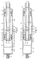
- the gas spring comprises a cylindrical body 10 having a closed end 12 on which is mounted a fixture 14.
- the opposite end of the cylinder 10 is closed off by an integral wall 16 which is apertured to allow passage of a hollow piston rod 18.
- the piston rod 18 slides in a guide 20 and through an air-tight seal 22.
- the piston rod 18 is attached to a further fixture (not shown).
- the gas spring is mounted on a vehicle body so as to control the pivotting movement of a horizontally pivotted closure member such as the hatchback, the lid of a luggage compartment, or the lid of the engine compartment.
- One of the fixtures (the fixture 14 or the fixture carried by the distal end of the piston rod 18) is attached to the body of a vehicle and the other is attached to the hatchback (or other movable member).
- the gas spring may, however, be used in many other applications.
- the piston rod 18 is attached to a piston 26 which is provided with a circular groove 28 in which is located a sealing ring 30, the groove 28 being wider than the sealing ring 30.
- the piston 26 and the sealing ring 30 separate first and second chambers 32 and 34 within the cylinder 10.
- the piston rod 18 is hollow and extends through the piston 26 to define an open end 40.
- a hole 42 in the piston rod 18 communicates with the chamber 34.
- a control rod 44 extends slidably through the hollow interior of the piston rod 18 and protrudes into the chamber 32 through the aperture 40 in the piston rod, the control rod 44 terminating in a cap 46 which carries a sealing ring 48.
- a reduced-diameter portion 50 of the control rod 44 extends between the cap 46 and an enlarged region 52 which carries a sealing ring 54.
- a passage-way 55 is defined between the outside of the enlarged region 52 of the control rod 44 and the inside wall of the piston rod 18. Sealing ring 54 makes an airtight seal with the interior wall of the hollow piston rod 18.
- the cylinder 10 is provided with a groove 56.
- a groove 56 Along another portion 58, however, of the interior wall of the cylinder, there is no such groove.
- the airtight seal 22 is held in position by a ring 60 which is itself locked into the cylinder 10 by a circumferential shoulder 62.
- the whole of the hollow interior of the cylinder 10 is filled with gas under pressure.
- unlatching of the hatchback causes the gas spring to open the hatchback to a predetermined intermediate position at which it stops.
- the user can cause the gas spring to re-start its opening movement, to lift the hatchback further, by applying a force to a control rod 44 as explained.
- the hatchback can then be caused to stop again, at any desired position, by removal of the force on the control rod.
- the arrangement of Figure 2 differs from the arrangement of Figure 1 in that the interior wall of the cylinder 10 has a first groove 56A and a second, axially spaced, groove 56B.
- a first un-grooved portion 58A is positioned between the groove 56A and the groove 56B, and a second un-grooved portion 58B is positioned between the groove 56B and the exit end of the cylinder 10.
- This movement can be stopped by removing the force on the control rod 44, so as to allow the control rod to revert to the position illustrated.
- the hatchback can thus be stopped at any desired position while the sealing ring 30 is in contact with the un-grooved wall portion 58A.
- the hatchback is lowered by the application of a lowering force, the resultant movement to the left of the piston 26 causing the sealing ring 30 to shift to the right (as viewed in the Figure) of the groove 28, and gas pressure can then transfer between chamber 32 and chamber 34 via the bores 64 and gap 65, thereby facilitating lowering of the hatchback under its weight even if the sealing ring 30 is in contact with an ungrooved portion of the cylinder wall.
- gas pressure transfer takes place freely through groove 56B and 56A as the piston 26 passes over the grooved portions.
- Gas pressure transfer can now take place between chamber 34 and chamber 32 through the aperture 42 and passageway 55.
- the piston 26 can thus start to move to the right, and the piston rod 18 thus starts to lift the hatchback.
- the user can cause the raising movement of the hatchback to stop at any desired position, by releasing the manual force on control rod 44.
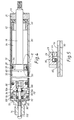
- the interior wall of the cylinder 10 not only has a groove 56 but it also has a concentric passageway 80 which extends over a substantial part of the length of the cylinder.
- the concentric passageway 80 is connected to the chamber 34 via a groove 82 in the fixing ring 60.
- the passageway 80 is connected to a valve arrangement indicated generally by the reference 84.
- the valve arrangement 84 comprises a body 86 which is sealingly mounted within the interior of the cylinder by means of a sealing ring 88.
- the end of the cylinder 10 is closed off by a boss 90 carrying the fixture 14.
- Intermediate members 92 and 94 together define an intermediate chamber 96 which is connected to the concentric passageway 80 via a radial bore 98.
- Body portion 92 is sealed against the wall of the cylinder 10 by a sealing ring 100.
- a control rod 102 extends slidingly through the body 90 and into and through the intermediate chamber 96.
- the control rod 102 passes through an opening 104 and has an enlarged portion 106 which is terminated by a nut 108 in a recess 110 which is in communication with the chamber 32.
- a sealing ring 111 seals around the stem of the control rod 102, and a further sealing ring 112 seals around the enlarged portion 106 of the control rod.
- the user presses on the end of the control rod 102 so as to move the control rod to the right as viewed in Figure 4.
- the enlarged portion 110 of the control rod 102 moves away from the sealing ring 112.
- Chamber 34 is now placed in communication with chamber 32 via groove 82, concentric passageway 80, radial bore 98, intermediate chamber 96, opening 104 and recess 110.
- the hatchback therefore starts to rise further.
- the operator can stop such further movement of the hatchback by releasing the force exerted on control rod 102.
- the control rod thus moves to the left again (as viewed in Figure 4) under the action of the pressure within chamber 32, and further movement of the hatchback stops.
- the hatchback can be lowered by applying a lowering force to it.
- the resultant movement of the piston 26 shifts the sealing ring 30 to the right hand side (as viewed in the Figure) of groove 28.
- Gas pressure transfer can take place between chambers 32 and 34 via the bores 64 and the gap 65.
- the enlarged portion 106 of the rod 102 produces a chamfer 114. Therefore, the pressure in the chamber 96 (acting through passageway 80 from chamber 34) produces a force acting on chamfer 114 tending to move the enlarged portion 106 out of the chamber 96. This force thus reduces the force which the user has to exert on the rod 102 to connect chamber 96 to chamber 32. In addition, if the user should attempt to lift the hatchback without moving the rod 102 to the released position, the resultant increased pressure in chamber 34 is able itself to move the enlarged diameter portion 106 out of the chamber 96, thus connecting chamber 34 to chamber 32. This reduces the pressure in chamber 34 which might otherwise damage the sealing ring 30.
Landscapes
- Engineering & Computer Science (AREA)
- General Engineering & Computer Science (AREA)
- Mechanical Engineering (AREA)
- Fluid-Damping Devices (AREA)
- Closing And Opening Devices For Wings, And Checks For Wings (AREA)
- Actuator (AREA)
Applications Claiming Priority (2)
| Application Number | Priority Date | Filing Date | Title |
|---|---|---|---|
| GB9520574 | 1995-10-09 | ||
| GB9520574A GB2305991B (en) | 1995-10-09 | 1995-10-09 | Gas spring |
Publications (2)
| Publication Number | Publication Date |
|---|---|
| EP0768476A1 true EP0768476A1 (fr) | 1997-04-16 |
| EP0768476B1 EP0768476B1 (fr) | 2001-09-12 |
Family
ID=10782001
Family Applications (1)
| Application Number | Title | Priority Date | Filing Date |
|---|---|---|---|
| EP96305421A Revoked EP0768476B1 (fr) | 1995-10-09 | 1996-07-24 | Ressort à gaz |
Country Status (5)
| Country | Link |
|---|---|
| US (1) | US5887857A (fr) |
| EP (1) | EP0768476B1 (fr) |
| DE (1) | DE69615121T2 (fr) |
| ES (1) | ES2162978T3 (fr) |
| GB (1) | GB2305991B (fr) |
Cited By (10)
| Publication number | Priority date | Publication date | Assignee | Title |
|---|---|---|---|---|
| EP0852303A1 (fr) * | 1997-01-07 | 1998-07-08 | Showa Corporation | Ressort à gaz |
| EP0852302A1 (fr) * | 1997-01-07 | 1998-07-08 | Showa Corporation | Ressort à gaz |
| ES2154997A1 (es) * | 1997-12-11 | 2001-04-16 | Stabilus Gmbh | Resorte de gas con funcion de parada intermedia y compensacion de la temperatura. |
| EP1074759A3 (fr) * | 1999-08-05 | 2003-04-23 | Diebolt International, Inc. | Ressort à gaz à course de retour temporisée |
| WO2004061327A1 (fr) * | 2003-01-03 | 2004-07-22 | Zimmer, Günther | Systeme de guidage comportant un dispositif pneumatique de ralentissement |
| EP1537803A1 (fr) * | 2002-10-09 | 2005-06-08 | Stabilus GmbH | Dispositif comprenant un élément réglable en hauteur |
| ES2304075A1 (es) * | 2005-12-20 | 2008-09-01 | Jose Javier Barandiaran Salaverria | Cilindro a gas. |
| EP2628973A3 (fr) * | 2012-02-17 | 2014-11-05 | AL-KO Kober AG | Élément de réglage hydropneumatique |
| CN106286690A (zh) * | 2016-08-12 | 2017-01-04 | 浙江工商大学 | 一种专用于太阳翼板吊挂装置的缓冲气缸 |
| CN106151360B (zh) * | 2016-08-12 | 2018-05-18 | 浙江工商大学 | 一种具有刹车缓冲功能的太阳翼板吊挂装置用刹车装置 |
Families Citing this family (37)
| Publication number | Priority date | Publication date | Assignee | Title |
|---|---|---|---|---|
| DE19618055C1 (de) * | 1996-05-06 | 1998-01-15 | Mannesmann Sachs Ag | Kolben-Zylinderaggregat mit wegabhängigem Dämpfkraftfeld |
| US5944154A (en) * | 1997-10-01 | 1999-08-31 | General Motor Corporation | Suspension damper with polygonal reservoir tube |
| US6199673B1 (en) * | 1998-10-22 | 2001-03-13 | Illinois Tool Works Inc. | Silent damper with anti-rattle shaft |
| US6513811B1 (en) * | 1999-09-02 | 2003-02-04 | Illinois Tool Works Inc. | Air damper with graphite coated lip seal |
| US6726219B2 (en) * | 1999-09-02 | 2004-04-27 | Illinois Tool Works Inc. | Air damper with graphite coated lip seal |
| US6352271B1 (en) * | 2000-07-12 | 2002-03-05 | Daniel A. Babcock | Cylinder for improving the handling of a vehicle in turns |
| DE10042030C1 (de) * | 2000-08-26 | 2002-02-07 | Sachs Race Eng Gmbh | Kolben-Zylinderaggregat mit mindestens einer Bypass-Nut im Zylinder |
| US6773002B2 (en) * | 2002-01-28 | 2004-08-10 | Barnes Group Inc. | Compression spring rod |
| US7000908B2 (en) * | 2002-01-29 | 2006-02-21 | Barnes Group Inc. | Tailgate stabilizer |
| CA2445466C (fr) * | 2002-10-17 | 2008-07-08 | Litens Automotive | Jambe de verrouillage |
| US8292274B2 (en) * | 2003-01-10 | 2012-10-23 | Barnes Group Inc. | Dampened compression spring rod |
| DE10307363B3 (de) * | 2003-02-21 | 2004-09-09 | Zf Sachs Ag | Schwingungsdämpfer mit hubabhängiger Dämpfkraft |
| US20050016803A1 (en) * | 2003-07-25 | 2005-01-27 | Chad Brummitt | Multiple stop gas spring for vehicle closure |
| DE10339188A1 (de) * | 2003-08-22 | 2005-03-10 | Suspa Holding Gmbh | Gasfeder |
| US6974001B2 (en) * | 2003-11-19 | 2005-12-13 | Arvinmeritor Technology, Llc. | Temperature compensating gas spring |
| DE102004026356B4 (de) * | 2004-05-26 | 2008-07-31 | Stabilus Gmbh | Zugfederanordnung |
| DE102004035613A1 (de) * | 2004-07-22 | 2006-03-16 | Stabilus Gmbh | Gasfeder mit Endlagendämpfung |
| US20060027955A1 (en) * | 2004-08-04 | 2006-02-09 | Barnes Group Inc., A Corporation Of Delaware | Non-linear spring system |
| US7387181B2 (en) * | 2004-10-04 | 2008-06-17 | Associated Spring Raymond | Hood lift system |
| US8262548B1 (en) | 2005-11-25 | 2012-09-11 | Plyo Systems, Llc | Air management for enhancing pneumatic rebound training |
| US7677539B2 (en) * | 2006-02-23 | 2010-03-16 | Barnes Group Inc. | Force control strut |
| US8123006B1 (en) * | 2007-04-13 | 2012-02-28 | Hayes Bicycle Group, Inc. | Lightweight gas spring design with volume compensator incorporated into a suspension fork for two wheeled vehicles |
| US8246019B2 (en) * | 2007-06-21 | 2012-08-21 | GM Global Technology Operations LLC | Air spring for vehicle closure |
| KR100894799B1 (ko) * | 2007-12-05 | 2009-04-22 | 주식회사 만도 | 쇽업소버 |
| JP5180153B2 (ja) * | 2009-06-23 | 2013-04-10 | カヤバ工業株式会社 | エアバネ構造 |
| US9834971B2 (en) * | 2010-03-17 | 2017-12-05 | Avm Industries, Llc | Lift assist and damper arrangement |
| US8480064B2 (en) | 2010-07-09 | 2013-07-09 | Specialized Bicycle Components, Inc. | Bicycle with suspension |
| US8740237B2 (en) | 2011-09-23 | 2014-06-03 | Specialized Bicycle Components, Inc. | Bicycle with suspension |
| US9188184B2 (en) | 2012-05-14 | 2015-11-17 | Barnes Group Inc. | Telescoping strut |
| CN103883660B (zh) * | 2014-02-25 | 2016-08-17 | 贺有云 | 双作用缓冲器 |
| DE102014117479C5 (de) | 2014-11-28 | 2024-11-28 | Brose Fahrzeugteile Se & Co. Kommanditgesellschaft, Bamberg | Antrieb für ein Verschlusselement eines Kraftfahrzeugs |
| CN106122354B (zh) * | 2016-08-12 | 2018-01-05 | 浙江工业大学 | 一种对太阳翼板吊挂装置进行刹车缓冲的刹车气缸 |
| CN106438824B (zh) * | 2016-08-12 | 2018-12-11 | 浙江工业大学 | 一种专用于太阳翼板吊挂装置的刹车气缸 |
| TWI589475B (zh) * | 2016-08-31 | 2017-07-01 | 巨大機械工業股份有限公司 | 可調式自行車座管結構及其自行車 |
| US11300172B2 (en) | 2020-01-29 | 2022-04-12 | Lockheed Martin Corporation | Load limiting breakaway device |
| DE102023000433A1 (de) | 2023-02-11 | 2024-08-22 | Stabilus Gmbh | Gasfedersystem mit wenigstens einer Gasfeder |
| US20250079490A1 (en) | 2023-08-31 | 2025-03-06 | Zeroavia Ltd. | Phosphoric Acid Replenishment |
Citations (5)
| Publication number | Priority date | Publication date | Assignee | Title |
|---|---|---|---|---|
| FR2376340A1 (fr) * | 1976-12-30 | 1978-07-28 | Stabilus Gmbh | Ressort pneumatique blocable en fonction de la charge |
| GB1528820A (en) | 1975-03-26 | 1978-10-18 | Stabilus Gmbh | Lockable spring |
| GB2087510A (en) * | 1980-09-11 | 1982-05-26 | Nissan Motor | A spring strut assembly |
| EP0396907A1 (fr) * | 1989-04-07 | 1990-11-14 | Stabilus GmbH | Dispositif de positionnement |
| FR2652140A1 (fr) * | 1989-09-21 | 1991-03-22 | Stabilus Gmbh | Appareil a cylindre de pression et piston. |
Family Cites Families (6)
| Publication number | Priority date | Publication date | Assignee | Title |
|---|---|---|---|---|
| US4113220A (en) * | 1977-01-31 | 1978-09-12 | Bliss & Laughlin Industries Incorporated | Adjustable gas cylinder chair control |
| DE3301544A1 (de) * | 1983-01-19 | 1984-07-19 | Stabilus Gmbh, 5400 Koblenz | Gasfeder als huborgan zum oeffnen von nach oben schwenkbaren klappen |
| DE3629250A1 (de) * | 1986-08-28 | 1988-03-03 | Stabilus Gmbh | Stufenlos blockierbare verstelleinrichtung |
| CH679116A5 (fr) * | 1989-05-10 | 1991-12-31 | Peter Reinhard | |
| DE3933360A1 (de) * | 1989-10-06 | 1991-04-18 | Stabilus Gmbh | Ausloesestift fuer ein stufenlos blockierbares hubaggregat, mit integriertem ueberdruckventil |
| GB2303193B (en) * | 1995-07-13 | 1998-10-14 | Draftex Ind Ltd | Gas spring |
-
1995
- 1995-10-09 GB GB9520574A patent/GB2305991B/en not_active Expired - Fee Related
-
1996
- 1996-07-24 EP EP96305421A patent/EP0768476B1/fr not_active Revoked
- 1996-07-24 DE DE69615121T patent/DE69615121T2/de not_active Revoked
- 1996-07-24 ES ES96305421T patent/ES2162978T3/es not_active Expired - Lifetime
- 1996-09-12 US US08/713,039 patent/US5887857A/en not_active Expired - Fee Related
Patent Citations (5)
| Publication number | Priority date | Publication date | Assignee | Title |
|---|---|---|---|---|
| GB1528820A (en) | 1975-03-26 | 1978-10-18 | Stabilus Gmbh | Lockable spring |
| FR2376340A1 (fr) * | 1976-12-30 | 1978-07-28 | Stabilus Gmbh | Ressort pneumatique blocable en fonction de la charge |
| GB2087510A (en) * | 1980-09-11 | 1982-05-26 | Nissan Motor | A spring strut assembly |
| EP0396907A1 (fr) * | 1989-04-07 | 1990-11-14 | Stabilus GmbH | Dispositif de positionnement |
| FR2652140A1 (fr) * | 1989-09-21 | 1991-03-22 | Stabilus Gmbh | Appareil a cylindre de pression et piston. |
Cited By (13)
| Publication number | Priority date | Publication date | Assignee | Title |
|---|---|---|---|---|
| EP0852302A1 (fr) * | 1997-01-07 | 1998-07-08 | Showa Corporation | Ressort à gaz |
| US5961102A (en) * | 1997-01-07 | 1999-10-05 | Showa Corproration | Gas spring |
| AU731364B2 (en) * | 1997-01-07 | 2001-03-29 | Showa Corporation | Gas spring |
| EP0852303A1 (fr) * | 1997-01-07 | 1998-07-08 | Showa Corporation | Ressort à gaz |
| ES2154997A1 (es) * | 1997-12-11 | 2001-04-16 | Stabilus Gmbh | Resorte de gas con funcion de parada intermedia y compensacion de la temperatura. |
| EP1074759A3 (fr) * | 1999-08-05 | 2003-04-23 | Diebolt International, Inc. | Ressort à gaz à course de retour temporisée |
| EP1537803A1 (fr) * | 2002-10-09 | 2005-06-08 | Stabilus GmbH | Dispositif comprenant un élément réglable en hauteur |
| WO2004061327A1 (fr) * | 2003-01-03 | 2004-07-22 | Zimmer, Günther | Systeme de guidage comportant un dispositif pneumatique de ralentissement |
| ES2304075A1 (es) * | 2005-12-20 | 2008-09-01 | Jose Javier Barandiaran Salaverria | Cilindro a gas. |
| ES2304075B1 (es) * | 2005-12-20 | 2009-07-02 | Jose Javier Barandiaran Salaverria | Cilindro a gas para controlar el abatimiento de partes moviles. |
| EP2628973A3 (fr) * | 2012-02-17 | 2014-11-05 | AL-KO Kober AG | Élément de réglage hydropneumatique |
| CN106286690A (zh) * | 2016-08-12 | 2017-01-04 | 浙江工商大学 | 一种专用于太阳翼板吊挂装置的缓冲气缸 |
| CN106151360B (zh) * | 2016-08-12 | 2018-05-18 | 浙江工商大学 | 一种具有刹车缓冲功能的太阳翼板吊挂装置用刹车装置 |
Also Published As
| Publication number | Publication date |
|---|---|
| GB2305991B (en) | 1999-07-07 |
| DE69615121T2 (de) | 2002-04-25 |
| US5887857A (en) | 1999-03-30 |
| GB9520574D0 (en) | 1995-12-13 |
| GB2305991A (en) | 1997-04-23 |
| ES2162978T3 (es) | 2002-01-16 |
| EP0768476B1 (fr) | 2001-09-12 |
| DE69615121D1 (de) | 2001-10-18 |
Similar Documents
| Publication | Publication Date | Title |
|---|---|---|
| EP0768476B1 (fr) | Ressort à gaz | |
| EP0753684B1 (fr) | Ressort à gaz | |
| EP0881408B1 (fr) | Ressort à gaz avec contrôle de vitesse | |
| US4647026A (en) | Pneumatic or hydropneumatic tension spring | |
| US4433759A (en) | Gas spring | |
| US5839719A (en) | Pneumatic strut for a motor vehicle with an adjustable limit position | |
| KR100621267B1 (ko) | 피스톤-실린더-유닛 | |
| US5799759A (en) | Hydraulic strut for a motor vehicle | |
| US4632228A (en) | Cylinder piston device | |
| US5988608A (en) | Piston-cylinder unit having a sealing valve | |
| US12146359B2 (en) | Drive assembly for a flap of a motor vehicle | |
| AU731364B2 (en) | Gas spring | |
| EP1686267A1 (fr) | Actionneur linéaire | |
| US5116028A (en) | Pressure tube-piston device | |
| KR102883629B1 (ko) | 자동차의 플랩용 구동 장치 | |
| US5862893A (en) | Fluid strut for a motor vehicle | |
| JPS6331014B2 (fr) | ||
| US4832318A (en) | Lifting telescoping tube | |
| GB2303194A (en) | Gas spring for hatchback | |
| EP0786607A1 (fr) | Ressort à gaz | |
| EP4435288A1 (fr) | Dispositif amortisseur de choc à gaz de traction | |
| JPH10287274A (ja) | バックドアの開閉制御装置 | |
| KR0170015B1 (ko) | 선형 유압식 모터 | |
| EP0939242B1 (fr) | Dispositif commandant le mouvement | |
| JPH0547878Y2 (fr) |
Legal Events
| Date | Code | Title | Description |
|---|---|---|---|
| PUAI | Public reference made under article 153(3) epc to a published international application that has entered the european phase |
Free format text: ORIGINAL CODE: 0009012 |
|
| AK | Designated contracting states |
Kind code of ref document: A1 Designated state(s): DE ES FR IT |
|
| 17P | Request for examination filed |
Effective date: 19970711 |
|
| RAP1 | Party data changed (applicant data changed or rights of an application transferred) |
Owner name: DRAFTEX INDUSTRIES LIMITED |
|
| GRAG | Despatch of communication of intention to grant |
Free format text: ORIGINAL CODE: EPIDOS AGRA |
|
| GRAG | Despatch of communication of intention to grant |
Free format text: ORIGINAL CODE: EPIDOS AGRA |
|
| 17Q | First examination report despatched |
Effective date: 19990924 |
|
| GRAG | Despatch of communication of intention to grant |
Free format text: ORIGINAL CODE: EPIDOS AGRA |
|
| GRAG | Despatch of communication of intention to grant |
Free format text: ORIGINAL CODE: EPIDOS AGRA |
|
| GRAH | Despatch of communication of intention to grant a patent |
Free format text: ORIGINAL CODE: EPIDOS IGRA |
|
| GRAG | Despatch of communication of intention to grant |
Free format text: ORIGINAL CODE: EPIDOS AGRA |
|
| GRAH | Despatch of communication of intention to grant a patent |
Free format text: ORIGINAL CODE: EPIDOS IGRA |
|
| GRAH | Despatch of communication of intention to grant a patent |
Free format text: ORIGINAL CODE: EPIDOS IGRA |
|
| GRAA | (expected) grant |
Free format text: ORIGINAL CODE: 0009210 |
|
| RAP1 | Party data changed (applicant data changed or rights of an application transferred) |
Owner name: TRELLEBORG AB |
|
| AK | Designated contracting states |
Kind code of ref document: B1 Designated state(s): DE ES FR IT |
|
| REF | Corresponds to: |
Ref document number: 69615121 Country of ref document: DE Date of ref document: 20011018 |
|
| REG | Reference to a national code |
Ref country code: ES Ref legal event code: FG2A Ref document number: 2162978 Country of ref document: ES Kind code of ref document: T3 |
|
| ET | Fr: translation filed | ||
| PLBQ | Unpublished change to opponent data |
Free format text: ORIGINAL CODE: EPIDOS OPPO |
|
| PLBI | Opposition filed |
Free format text: ORIGINAL CODE: 0009260 |
|
| PLBF | Reply of patent proprietor to notice(s) of opposition |
Free format text: ORIGINAL CODE: EPIDOS OBSO |
|
| 26 | Opposition filed |
Opponent name: STABILUS GMBH Effective date: 20020524 |
|
| PLBF | Reply of patent proprietor to notice(s) of opposition |
Free format text: ORIGINAL CODE: EPIDOS OBSO |
|
| PLBF | Reply of patent proprietor to notice(s) of opposition |
Free format text: ORIGINAL CODE: EPIDOS OBSO |
|
| APBP | Date of receipt of notice of appeal recorded |
Free format text: ORIGINAL CODE: EPIDOSNNOA2O |
|
| APBQ | Date of receipt of statement of grounds of appeal recorded |
Free format text: ORIGINAL CODE: EPIDOSNNOA3O |
|
| APAA | Appeal reference recorded |
Free format text: ORIGINAL CODE: EPIDOS REFN |
|
| PGFP | Annual fee paid to national office [announced via postgrant information from national office to epo] |
Ref country code: FR Payment date: 20050708 Year of fee payment: 10 |
|
| PGFP | Annual fee paid to national office [announced via postgrant information from national office to epo] |
Ref country code: DE Payment date: 20050721 Year of fee payment: 10 |
|
| PGFP | Annual fee paid to national office [announced via postgrant information from national office to epo] |
Ref country code: ES Payment date: 20050818 Year of fee payment: 10 |
|
| APAH | Appeal reference modified |
Free format text: ORIGINAL CODE: EPIDOSCREFNO |
|
| APBU | Appeal procedure closed |
Free format text: ORIGINAL CODE: EPIDOSNNOA9O |
|
| RDAF | Communication despatched that patent is revoked |
Free format text: ORIGINAL CODE: EPIDOSNREV1 |
|
| RDAG | Patent revoked |
Free format text: ORIGINAL CODE: 0009271 |
|
| STAA | Information on the status of an ep patent application or granted ep patent |
Free format text: STATUS: PATENT REVOKED |
|
| 27W | Patent revoked |
Effective date: 20060130 |
|
| PGFP | Annual fee paid to national office [announced via postgrant information from national office to epo] |
Ref country code: IT Payment date: 20060731 Year of fee payment: 11 |