EP0768486B1 - Vorgesteuertes Fluidumventil - Google Patents
Vorgesteuertes Fluidumventil Download PDFInfo
- Publication number
- EP0768486B1 EP0768486B1 EP96307265A EP96307265A EP0768486B1 EP 0768486 B1 EP0768486 B1 EP 0768486B1 EP 96307265 A EP96307265 A EP 96307265A EP 96307265 A EP96307265 A EP 96307265A EP 0768486 B1 EP0768486 B1 EP 0768486B1
- Authority
- EP
- European Patent Office
- Prior art keywords
- diaphragm
- gas purge
- purge valve
- chamber
- valve according
- Prior art date
- Legal status (The legal status is an assumption and is not a legal conclusion. Google has not performed a legal analysis and makes no representation as to the accuracy of the status listed.)
- Expired - Lifetime
Links
- 239000012530 fluid Substances 0.000 title claims description 15
- 238000010926 purge Methods 0.000 claims abstract description 71
- 239000007788 liquid Substances 0.000 claims abstract description 68
- 238000013022 venting Methods 0.000 claims abstract description 14
- 238000007789 sealing Methods 0.000 claims description 27
- 238000006073 displacement reaction Methods 0.000 claims description 7
- 238000007599 discharging Methods 0.000 claims description 5
- 239000013013 elastic material Substances 0.000 claims 1
- 239000012528 membrane Substances 0.000 description 5
- 239000010865 sewage Substances 0.000 description 4
- XLYOFNOQVPJJNP-UHFFFAOYSA-N water Substances O XLYOFNOQVPJJNP-UHFFFAOYSA-N 0.000 description 3
- 238000009826 distribution Methods 0.000 description 2
- 230000002093 peripheral effect Effects 0.000 description 2
- 230000035939 shock Effects 0.000 description 2
- 230000015572 biosynthetic process Effects 0.000 description 1
- 238000004140 cleaning Methods 0.000 description 1
- 230000006835 compression Effects 0.000 description 1
- 238000007906 compression Methods 0.000 description 1
- 230000003028 elevating effect Effects 0.000 description 1
- 230000003628 erosive effect Effects 0.000 description 1
- -1 for example Substances 0.000 description 1
- 230000005484 gravity Effects 0.000 description 1
- 238000005304 joining Methods 0.000 description 1
- 230000007257 malfunction Effects 0.000 description 1
- 238000004519 manufacturing process Methods 0.000 description 1
- 239000000463 material Substances 0.000 description 1
- 230000000149 penetrating effect Effects 0.000 description 1
- 229920001296 polysiloxane Polymers 0.000 description 1
- 239000012858 resilient material Substances 0.000 description 1
Images





Classifications
-
- F—MECHANICAL ENGINEERING; LIGHTING; HEATING; WEAPONS; BLASTING
- F16—ENGINEERING ELEMENTS AND UNITS; GENERAL MEASURES FOR PRODUCING AND MAINTAINING EFFECTIVE FUNCTIONING OF MACHINES OR INSTALLATIONS; THERMAL INSULATION IN GENERAL
- F16K—VALVES; TAPS; COCKS; ACTUATING-FLOATS; DEVICES FOR VENTING OR AERATING
- F16K7/00—Diaphragm valves or cut-off apparatus, e.g. with a member deformed, but not moved bodily, to close the passage ; Pinch valves
- F16K7/12—Diaphragm valves or cut-off apparatus, e.g. with a member deformed, but not moved bodily, to close the passage ; Pinch valves with flat, dished, or bowl-shaped diaphragm
- F16K7/14—Diaphragm valves or cut-off apparatus, e.g. with a member deformed, but not moved bodily, to close the passage ; Pinch valves with flat, dished, or bowl-shaped diaphragm arranged to be deformed against a flat seat
- F16K7/17—Diaphragm valves or cut-off apparatus, e.g. with a member deformed, but not moved bodily, to close the passage ; Pinch valves with flat, dished, or bowl-shaped diaphragm arranged to be deformed against a flat seat the diaphragm being actuated by fluid pressure
-
- F—MECHANICAL ENGINEERING; LIGHTING; HEATING; WEAPONS; BLASTING
- F16—ENGINEERING ELEMENTS AND UNITS; GENERAL MEASURES FOR PRODUCING AND MAINTAINING EFFECTIVE FUNCTIONING OF MACHINES OR INSTALLATIONS; THERMAL INSULATION IN GENERAL
- F16K—VALVES; TAPS; COCKS; ACTUATING-FLOATS; DEVICES FOR VENTING OR AERATING
- F16K24/00—Devices, e.g. valves, for venting or aerating enclosures
-
- F—MECHANICAL ENGINEERING; LIGHTING; HEATING; WEAPONS; BLASTING
- F16—ENGINEERING ELEMENTS AND UNITS; GENERAL MEASURES FOR PRODUCING AND MAINTAINING EFFECTIVE FUNCTIONING OF MACHINES OR INSTALLATIONS; THERMAL INSULATION IN GENERAL
- F16K—VALVES; TAPS; COCKS; ACTUATING-FLOATS; DEVICES FOR VENTING OR AERATING
- F16K24/00—Devices, e.g. valves, for venting or aerating enclosures
- F16K24/04—Devices, e.g. valves, for venting or aerating enclosures for venting only
-
- Y—GENERAL TAGGING OF NEW TECHNOLOGICAL DEVELOPMENTS; GENERAL TAGGING OF CROSS-SECTIONAL TECHNOLOGIES SPANNING OVER SEVERAL SECTIONS OF THE IPC; TECHNICAL SUBJECTS COVERED BY FORMER USPC CROSS-REFERENCE ART COLLECTIONS [XRACs] AND DIGESTS
- Y10—TECHNICAL SUBJECTS COVERED BY FORMER USPC
- Y10T—TECHNICAL SUBJECTS COVERED BY FORMER US CLASSIFICATION
- Y10T137/00—Fluid handling
- Y10T137/2931—Diverse fluid containing pressure systems
- Y10T137/3003—Fluid separating traps or vents
- Y10T137/3084—Discriminating outlet for gas
- Y10T137/309—Fluid sensing valve
- Y10T137/3099—Float responsive
-
- Y—GENERAL TAGGING OF NEW TECHNOLOGICAL DEVELOPMENTS; GENERAL TAGGING OF CROSS-SECTIONAL TECHNOLOGIES SPANNING OVER SEVERAL SECTIONS OF THE IPC; TECHNICAL SUBJECTS COVERED BY FORMER USPC CROSS-REFERENCE ART COLLECTIONS [XRACs] AND DIGESTS
- Y10—TECHNICAL SUBJECTS COVERED BY FORMER USPC
- Y10T—TECHNICAL SUBJECTS COVERED BY FORMER US CLASSIFICATION
- Y10T137/00—Fluid handling
- Y10T137/7722—Line condition change responsive valves
- Y10T137/7758—Pilot or servo controlled
- Y10T137/7762—Fluid pressure type
- Y10T137/7764—Choked or throttled pressure type
- Y10T137/7765—Pilot valve within main valve head
-
- Y—GENERAL TAGGING OF NEW TECHNOLOGICAL DEVELOPMENTS; GENERAL TAGGING OF CROSS-SECTIONAL TECHNOLOGIES SPANNING OVER SEVERAL SECTIONS OF THE IPC; TECHNICAL SUBJECTS COVERED BY FORMER USPC CROSS-REFERENCE ART COLLECTIONS [XRACs] AND DIGESTS
- Y10—TECHNICAL SUBJECTS COVERED BY FORMER USPC
- Y10T—TECHNICAL SUBJECTS COVERED BY FORMER US CLASSIFICATION
- Y10T137/00—Fluid handling
- Y10T137/7722—Line condition change responsive valves
- Y10T137/7758—Pilot or servo controlled
- Y10T137/7762—Fluid pressure type
- Y10T137/7764—Choked or throttled pressure type
- Y10T137/7766—Choked passage through main valve head
-
- Y—GENERAL TAGGING OF NEW TECHNOLOGICAL DEVELOPMENTS; GENERAL TAGGING OF CROSS-SECTIONAL TECHNOLOGIES SPANNING OVER SEVERAL SECTIONS OF THE IPC; TECHNICAL SUBJECTS COVERED BY FORMER USPC CROSS-REFERENCE ART COLLECTIONS [XRACs] AND DIGESTS
- Y10—TECHNICAL SUBJECTS COVERED BY FORMER USPC
- Y10T—TECHNICAL SUBJECTS COVERED BY FORMER US CLASSIFICATION
- Y10T137/00—Fluid handling
- Y10T137/7722—Line condition change responsive valves
- Y10T137/7771—Bi-directional flow valves
- Y10T137/778—Axes of ports co-axial
Definitions
- the present invention is in the field of fluid flow valves and is particularly, but not exclusively, concerned with such valves which are designed to serve as gas discharge valves or gas purge valves.
- Such air purge valves are installed in liquid systems such as, for example, water mains distribution lines or sewage collection systems, or liquid tanks, and are designed to discharge air (typically in water supply systems) or other gasses (e.g. in sewage systems), thus avoiding the formation of gas pockets and gas bubbles which interfere with the liquid flow and also have bad influence on accessories fitted to the liquid system.
- This type of air purge valve is known as the "automatic kind" in which in view of the relatively small dimensions of the aperture, the valve cannot cope with the situation when large quantities of air have to be discharged, wherein not all the air is released and some of it passes into the line, causing build-up of air pressure and ultimately the creation of an air lock.
- a second type of air purge valves typically comprises a spherical float located in a housing which is coupled at a lower end thereof to the system to be vented and is provided at its upper end with a venting aperture.
- a spherical float located in a housing which is coupled at a lower end thereof to the system to be vented and is provided at its upper end with a venting aperture.
- US-A-5449018 which forms a basis for the preamble of claim 1, discloses a flow control valve having a housing, an inlet to the housing for connecting to a liquid system to be purged, a flexible diaphragm maintained in the housing serving to divide the housing into first and second chambers, the first chamber communicating with the inlet.
- An aperture of restricted dimensions is formed in the diaphragm and a diaphragm seating is formed in the first chamber which is engagable by the diaphragm.
- a gas purge valve comprising a housing; an inlet to said housing for connecting to a liquid system to be purged; a flexible diaphragm maintained in said housing and serving to divide it into first and second chambers; said first chamber communicating with said inlet; an aperture of restricted dimensions formed in said diaphragm; a diaphragm seating formed in said first chamber and engageable by said diaphragm; characterised by a pilot valve controlled first outlet formed in said second chamber; a second outlet formed in said first chamber, said second outlet being sealed when said diaphragm engages said diaphragm seating; the arrangement being such that said pilot valve is displaceable between a first position in which gas is discharged from said second chamber so as to vent the second chamber and a second position in response to liquid presence, so as to seal said first outlet; whilst said diaphragm is displaceable in response to differential pressure created by said venting into unsealing said second outlet for full venting of said first chamber.
- said diaphragm seating is annular and said diaphragm is essentially circular with its perimeter flanged between the first and second chambers being clamped to one another and said diaphragm is normally biassed against said diaphragm seating.
- the pilot valve comprises an inlet and an outlet which are substantially circular openings and a spherical float member floatingly displaceable between said inlet and outlet openings; said openings having a diameter smaller than the diameter of said spherical float member, wherein said float member sealingly engages at least said outlet opening.
- the aperture of said diaphragm is smaller than said first outlet of said second chamber and said second outlet is essentially bigger than said first outlet.
- the valve may be used for preventing collapse of the liquid system when it is being drained.
- said float member sealingly engages also the inlet opening of said pilot valve so as to prevent gas flow into the housing during draining said liquid system, thus resulting in pressure decrease in both said first and second chambers, entailing disposition of the diaphragm from its normally sealing position to an unsealing position, allowing venting of the liquid system.
- the size of said aperture's section area at the diaphragm's sealing position is smaller than at an unsealing position, thereby changing the flow behavior so that on the one hand, displacement motion of the diaphragm from the unsealing position slows down towards the sealing position.
- the size of said aperture's section area is variable by an interposing member comprising a stem projecting towards said aperture and coaxial with said aperture; at least at the sealing position of the diaphragm a portion of the stem is encircled by the aperture; said stem having different cross sections along its longitudinal axis.
- said stem projects from a top surface of the second chamber and has a wider cross-section at a bottom end thereof extending adjacent said aperture at the sealing position of said diaphragm.
- the stem may be displaceable along its longitudinal axis by a manually operated handle.
- a stem having a conical or exponential or stepped profile is suitable.
- the gas purge valve may further comprise additional accessories such as a liquid relief valve for discharging liquid at high pressure above a predetermined pressure threshold, an automatic gas purge valve for discharging substantially small amounts of gas, a liquid indicator for indicating the presence of liquid in the liquid system, etc. Either of these accessories may be positioned in either the first or second chamber.
- said pilot valve may be an automatic gas purge valve.
- the gas purge valve may further comprise a fluid flow control assembly comprising a sealing valve mounted on a stem movable with respect to a fixed sealing valve seat within the first chamber of the housing, between an open position and a closed position.
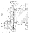
- a gas purge valve comprising a two-piece housing 2 consisting of a lower portion 4 and an upper portion 6 , which are screw-clamped together by bolts 8 and nuts 10 at their joining peripheral flanges 12 and 13.
- the diaphragm 14 has a substantially circular central aperture 16 and it divides the housing 2 into a first chamber 18 and a second chamber 20 at the bottom and top portions, respectively.
- the first chamber 18 has at its lower end an inlet opening 22 with a flanged end 24 for connecting to a liquid system such as a mains water distribution line or a sewage system (not shown).
- a liquid system such as a mains water distribution line or a sewage system (not shown).
- the second chamber 20 has a first outlet 26 with an internally screw-tapped boss 27 to which is screw-fitted a pilot valve assembly generally designated 30 and comprising an inlet 32 communicating with said outlet 26 , and an outlet 34 of essentially similar dimensions as of inlet 32.
- a sphere-like float member 36 is displaceable between a lower position in which it rests on support ribs 38 at the inlet 32 , allowing fluid flow between the ribs 38 , and between an upper position in which it sealingly bears against an " O "-ring 40 accommodated at the circular outlet 34.
- a second outlet 42 is formed near a top end of the lower portion 4 , reinforced by ribs 44 and bound by an annular diaphragm seating 46, providing a seat for the diaphragm 14 and ensuring sealing of the outlet 42 by said diaphragm.
- cross-section area of the aperture 16 is substantially smaller than that of the inlet 32 and outlet 34 of the pilot valve 30 .
- the gas purge valve is in its so-called “rest” position in which no fluid flows in the liquid system.
- FIG. 2 of the drawings illustrating the gas purge valve according to the present invention in its so-called “open” or “un-sealed” position.
- This position occurs, for example, when the mains liquid supply line is being filled with liquid, wherein air (or other gasses in case of a sewage collection system) enters the valve via inlet 22 of the housing.
- air or other gasses in case of a sewage collection system enters the valve via inlet 22 of the housing.
- air or other gasses in case of a sewage collection system enters the valve via inlet 22 of the housing.
- air is pressurized at the top chamber 20 to above external atmospheric pressure and thus exits through the pilot valve 30 via gaps between the ribs 38, resulting in pressure decrease in chamber 20 with respect to chamber 18 , in consequence of which the flexible diaphragm 14 raises and thus disengages the diaphragm seating 46 , unsealing the outlet 42 and enabling massive air discharge therethrough.
- the diaphragm 14 may be normally biassed against said diaphragm seating 46 or may be in slack contact with the seating, whereby higher liquid pressure shall be required to cause sealing of the outlet 42.
- the valve according to the present invention is suitable also for venting a liquid system being drained, so as to prevent collapsing of its walls and accessory members under vacuum.
- a liquid system being drained so as to prevent collapsing of its walls and accessory members under vacuum.
- the inlet opening 32 of the pilot valve 30 is a continues circular opening and comprises an " O "-ring for sealing engagement with the float member 36 when the latter is in its lowermost position, wherein air is prevented from entering the gas purge valve.
- liquid evacuates the housing 2 causing pressure decrease within the housing 2 . Since the pressure within the housing is substantially lower than the external, atmospheric pressure, and since air cannot enter the top chamber 20 via the pilot valve 30, the external air at atmospheric pressure pushes the diaphragm 14 to its unsealing position and enters via opening 42, thus venting the liquid system, preventing it from collapsing.
- the float member 36 may be itself coated with a resilient material so as to sealingly engage the circular inlet 32' or outlet 34 as may be the case.
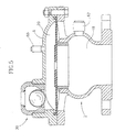
- FIG. 5 of the drawings there is illustrated a gas purge valve according to the present invention on which an automatic air purge valve 60 (schematically illustrated) is mounted on the upper portion 6 of the housing 2 .
- an automatic air purge valve is in particular suitable for discharging substantially small amounts of gas (regardless of its pressure) and is disclosed, for example, in U.S. Patent No. 4,770,201, incorporated herein by reference.
- the automatic gas purge valve may be positioned so as to discharge gas either from the top chamber 20 as seen in Fig. 5 or, from the bottom chamber 18 (not illustrated).
- the gas purge valve may incorporate an integral liquid relief valve 62 (schematically illustrated), the purpose of which is to discharge liquid from the housing at a pressure above a predetermined threshold, as known per se.
- the diaphragm slowly ends its displacement towards the sealing position, so as to prevent shock waves known as "hammering" in the liquid system.
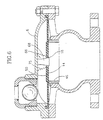
- Obtaining such characters may be by a flow behavior regulator 66 as seen in Fig. 6 of the drawings, in which such a regulator comprises a stem 68 projecting downwardly from the upper portion 6 and penetrating into the opening 16 of the diaphragm 14 .
- the stem 68 has at its lower portion a tapering cross-section which ensures that the cross-section area of aperture 16 is minimal at the sealing position and it increases towards the unsealing position, as can readily be understood.
- the longitudinal cross-section of the stem may alternatively be exponential or stepped, etc. in accordance with specific flow behavior requirements.
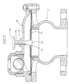
- Fig. 7 of the drawings illustrates a screw-threaded shaft 70 rotatably mounted within an internally threaded boss 72 at the top portion of the housing 2 , with a handle 74 for rotating the shaft 70 so as to axially displace it with respect to the aperture 16 of diaphragm 14, thus elevating or lowering the tapering end portion 76 of the shaft 70 as can be appreciated, for obtaining different flow characters of fluid flow through the aperture 16.
- a conical compression spring 75 having one end thereof bearing against a top wall of the housing and an opposed end bearing against the top surface 50 of the diaphragm 14 , whereby said diaphragm is biased against the diaphragm seating 46 into the sealing position.
- the diaphragm 77 is pre-stressed over the diaphragm seating 46, with its peripheral portion clamped between adjacent flange portions 78 and 79 of the lower portion 4' and the upper portion 6' of the housing 2 , whereby the diaphragm 77 is biased into the sealing position and where a higher preliminary force is required to shift the diaphragm into the unsealing position.
- Fig. 9 of the drawings is another embodiment of the present invention in which the gas purge valve is integrally provided with a fluid flow control assembly, namely a faucet, generally designated 80 comprising a valve member 82 linked to a screw-threaded stem 84 adapted for axial displacement within a corresponding screw-threaded bushing 86 fixed to the bottom portion 4 of the housing 2 by radial ribs 88 .
- the stem 84 is rotatably supported by a boss 90 at the top portion 6 of the housing 2 and is rotatable by a handle (not shown) so as to axially displace the valve member 82 with respect to an annular valve seat 94 .
- the valve 82 comprises adjacent its perimeter a seal 96 adapted for engaging with the valve seat 94 .
- Fig. 9 the fluid faucet 80 is seen in a closed position in which the valve 82 sealingly engages the valve seat 94 , whereby liquid passage between the bottom chamber 18 and the top chamber 20 is prevented.
- This situation is useful for servicing the gas purge valve, e.g. cleaning, repairing, etc.
- rotating the stem entails disengagement of the valve 82 from the valve seat 94 , whereby the gas purge valve may return to normal operation.
- a flag member 100 is attached to the float member 36' and is adapted to project from the outlet opening 34 of the pilot valve 30 .
- the arrangement is such that at the presence of liquid within the upper chamber 20, the float member 34' moves upward with the flag member 100 projecting from the housing 2 , indicating the presence of liquid.
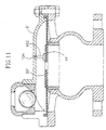
- Fig. 11 illustrates another embodiment of a liquid indicator where a flag member 102 is attached to the top surface 50' of the diaphragm 14'.
- the flag member 102 is adapted for projecting through an aperture 104 at the upper portion 6 ', whereby at the absence of liquid within the valve said flag member projects from the housing , while at the presence of liquid within the valve, the flag member is retracted as shown in Fig. 11.
- gas purge valve may comprise any of the above-mentioned accessories, e.g. automatic gas purge valve, liquid relief valve, liquid flow regulator, fluid indicator, liquid flow control assembly, etc. at any required combination.
Landscapes
- Engineering & Computer Science (AREA)
- General Engineering & Computer Science (AREA)
- Mechanical Engineering (AREA)
- Physics & Mathematics (AREA)
- Fluid Mechanics (AREA)
- Fluid-Driven Valves (AREA)
- Details Of Valves (AREA)
- Self-Closing Valves And Venting Or Aerating Valves (AREA)
Claims (22)
- Gas-Ablassventil, aufweisend: ein Gehäuse (2): einen Einlass (22) zu dem Gehäuse (2) zum Anschließen an ein Flüssigkeitssystem, das entgast werden soll; eine flexible Scheidewand (14), die in dem Gehäuse (2) gehalten wird und dazu dient, dieses in erste (18) und zweite (20) Kammern zu unterteilen, wobei die erste Kammer (18) mit dem Einlass (22) in kommunizierender Verbindung steht; eine in dieser Scheidewand (14) ausgebildete Öffnung (16) mit beschränkten Abmessungen; eine Scheidewandauflage (46), die in der ersten Kammer (18) ausgebildet ist und von der Scheidewand (14) überdeckbar ist, gekennzeichnet durch ein mit Vorsteuerventil (30) gesteuerten ersten Auslass (26), der in der zweiten Kammer (20) ausgebildet ist; einen zweiten Auslass (42), der in der ersten Kammer (18) ausgebildet ist, wobei der zweite Auslass geschlossen wird, wenn die Scheidewand (14) die Scheidewandauflage (46) überdeckt; wobei die Anordnung derart ist, dass das Vorsteuerventil (30) auslenkbar ist zwischen einer ersten Stellung, in der Gas aus der zweiten Kammer (20) abgelassen wird, um die zweite Kammer zu entlüften, und einer zweiten Stellung in Reaktion auf das Vorhandensein von Flüssigkeit, so dass der erste Auslass (26) geschlossen wird, während die Scheidewand (14) auslenkbar ist in Reaktion auf den Differentialdruck, der erzeugt wird durch das Entlüften in das Öffnen des zweiten Auslasses (42) für ein volles Entlüften der ersten Kammer.
- Gas-Ablassventil nach Anspruch 1, bei welchem die Scheidewand (14) normalerweise gegen die Scheidewandauflage (46) vorbelastet ist.
- Gas-Ablassventil nach Anspruch 1, bei welchem die Scheidewandauflage (46) ringförmig ist und die Scheidewand (14) im wesentlichen kreisförmig ist mit ihrem Umfang angeflanscht zwischen der ersten und der zweiten Kammer, die miteinander festgespannt sind.
- Gas-Ablassventil nach Anspruch 1, bei welchem das Vorsteuerventil (30) einen Einlass (32) und einen Auslass (34) aufweist. die im wesentlichen kreisförmige Öffnungen sind, sowie einen kugelförmigen Schwimmerkörper (36), der zwischen den Einlass- und Auslassöffnungen schwimmend verstellbar ist, wobei die Öffnungen einen Durchmesser haben, der kleiner ist als der Durchmesser des kugelförmigen Schwimmerkörpers (36) und wobei der Schwimmerkörper zur schließenden Überdeckung mindestens der Auslassöffnung (34) ausgelegt ist.
- Gas-Ablassventil nach Anspruch 4, bei welchem der Schwimmerkörper (36) mit einem elastischen Material überzogen ist.
- Gas-Ablassventil nach Anspruch 1, bei welchem die Öffnung (16) der Scheidewand (14) kleiner ist als der erste Auslass (26) der zweiten Kammer (20) und der zweite Auslass (44) wesentlich größer ist als der erste Auslass (26).
- Gas-Ablassventil nach Anspruch 4, bei welchem der Schwimmerkörper (36) auch die Einlassöffnung (32) des Vorsteuerventils (30) schließend überdeckt, um so Gasströmung in das Gehäuse (2) zu verhindern; wobei ein Entleeren des Flüssigkeitssystems einen Druckabfall sowohl in der ersten als auch in der zweiten Kammer (18, 20) zur Folge hat, was eine Stellungsänderung der Scheidewand (14) von der normalerweise schließenden Stellung zu einer öffnenden Stellung zur Folge hat und ein Entlüften des Flüssigkeitssystems ermöglicht.
- Gas-Ablassventil nach Anspruch 1, bei welchem die Größe der Querschnittfläche der Öffnung an der schließenden Stellung der Scheidewand kleiner ist als an der öffnenden Stellung, wodurch das Strömungsverhalten derart geändert wird, dass an der einen Seite die Auslenkbewegung der Scheidewand (14) aus der öffnenden Stellung in Richtung auf die schließende Stellung langsamer wird.
- Gas-Ablassventil nach Anspruch 8, bei welchem die Größe der Querschnittfläche der Öffnung mit Hilfe eines zwischenschaltenden Teils variabel ist. welches Teil einen Schaft (68) aufweist, der in Richtung der Öffnung (16) ragt und mit der Öffnung koaxial ist, wobei mindestens in der schließenden Stellung der Scheidewand (14) ein Abschnitt des Schaftes (68) von der Öffnung (16) umgeben ist und wobei der Schaft entlang seiner Längsachse unterschiedliche Querschnitte hat.
- Gas-Ablassventil nach Anspruch 9, bei welchem der Schaft (68) von einer Oberseite der zweiten Kammer (20) hervorragt und an seinem unteren Ende einen breiteren Querschnitt hat, das angrenzend an der Öffnung (16) in der schließenden Stellung der Scheidewand (14) verläuft.
- Gas-Ablassventil nach Anspruch 10, bei welchem der Querschnitt des Schaftes (68) konisch oder exponentiell ist oder eine abgestufte Konfiguration hat.
- Gas-Ablassventil nach Anspruch 10, bei welchem der Schaft 68) entlang seiner Längsachse mit Hilfe einer manuell betätigten Griffvorrichtung (74) extern verstellbar ist.
- Gas-Ablassventil nach Anspruch 1, bei welchem das Gehäuse (2) ferner aufweist: ein Flüssigkeitsdruckbegrenzungsventil (62) zum Ablassen von Flüssigkeit bei hohem Druck oberhalb eines vorbestimmten Druckgrenzwertes, wobei das Flüssigkeitsdruckbegrenzungsventil (62) entweder in der ersten oder in der zweiten Kammer (18, 20) angeordnet ist.
- Gas-Ablassventil nach Anspruch 1, bei welchem das Gehäuse (2) ferner aufweist: ein selbsttätiges Gas-Ablassventil (60) zum Ablassen von im wesentlichen geringen Mengen Gas, wobei das Gas-Ablassventil (60) entweder mit der ersten Kammer (18) oder mit der zweiten Kammer (20) verbunden ist.
- Gas-Ablassventil nach Anspruch 1 oder 14, bei welchem das Vorsteuerventil (30) ein Gas-Ablassventil ist.
- Gas-Ablassventil nach Anspruch 1, wobei das Ventil ferner aufweist: eine Flüssigkeitsanzeige (102) zum Anzeigen des Vorhandenseins von Flüssigkeit in dem Flüssigkeitssystem
- Gas-Ablassventil nach Anspruch 16, bei welchem die Flüssigkeitsanzeige aus einem zurückziehbaren Anzeigeteil (100) in Verbindung mit einem Schwimmerkörper (36') des Vorsteuerventils besteht, wobei das Anzeigeteil in Reaktion auf das Vorhandensein von Flüssigkeit im Inneren der zweiten Kammer von dem Gehäuse hervorsteht.
- Gas-Ablassventil nach Anspruch 16, bei welchem die Flüssigkeitsanzeige aus einem zurückziehbaren Anzeigeteil in Verbindung mit der Scheidewand (14') besteht, wodurch bei Abwesenheit von Flüssigkeit im Inneren des Gehäuses das Anzeigeteil (102) von dem Gehäuse hervorragt.
- Gas-Ablassventil nach Anspruch 1, wobei das Ventil ferner eine Anordnung (80) zur Fluidstromregelung aufweist, aufweisend ein schließendes Ventil (82), das auf einem Schaft (84) aufgebaut ist und in bezug auf einen fest angeordneten, schließenden Ventilsitz (94) im Inneren der ersten Kammer (18) des Gehäuses (2) zwischen einer offenen Stellung und einer geschlossenen Stellung beweglich ist.
- Gas-Ablassventil nach Anspruch 9 oder 19, bei welchem das zwischenschaltende Teil (76) und die Anordnung (80) zur Fluidstromregelung einen gemeinsamen Schaft (84) haben.
- Gas-Ablassventil nach Anspruch 2, aufweisend ein Federelement zum Vorbelasten der Scheidewand.
- Gas-Ablassventil nach Anspruch 2, bei welchem die Scheidewand (14) über der Scheidewandauflage (46) vorgespannt ist.
Applications Claiming Priority (2)
| Application Number | Priority Date | Filing Date | Title |
|---|---|---|---|
| IL11558695A IL115586A (en) | 1995-10-12 | 1995-10-12 | Pilot operated fluid valve |
| IL11558695 | 1995-10-12 |
Publications (2)
| Publication Number | Publication Date |
|---|---|
| EP0768486A1 EP0768486A1 (de) | 1997-04-16 |
| EP0768486B1 true EP0768486B1 (de) | 2001-04-18 |
Family
ID=11068074
Family Applications (1)
| Application Number | Title | Priority Date | Filing Date |
|---|---|---|---|
| EP96307265A Expired - Lifetime EP0768486B1 (de) | 1995-10-12 | 1996-10-04 | Vorgesteuertes Fluidumventil |
Country Status (9)
| Country | Link |
|---|---|
| US (1) | US6105608A (de) |
| EP (1) | EP0768486B1 (de) |
| AT (1) | ATE200702T1 (de) |
| AU (1) | AU703830B2 (de) |
| CA (1) | CA2187601C (de) |
| DE (1) | DE69612535T2 (de) |
| ES (1) | ES2156983T3 (de) |
| IL (1) | IL115586A (de) |
| ZA (1) | ZA968445B (de) |
Families Citing this family (21)
| Publication number | Priority date | Publication date | Assignee | Title |
|---|---|---|---|---|
| US6914531B1 (en) * | 1998-06-17 | 2005-07-05 | Richard Young | Apparatus for flow detection, measurement and control and method for use of same |
| DE10061306A1 (de) * | 2000-12-08 | 2002-07-11 | Mann & Hummel Filter | Druckregelventil mit einer druckbeaufschlagten Membran |
| US6668876B2 (en) * | 2001-06-14 | 2003-12-30 | Siemens Vdo Automotive, Incorporated | Method for fuel vapor pressure management |
| US6971625B2 (en) * | 2002-11-05 | 2005-12-06 | Parker Hannifin Corporation | Pilot operated valve with variable piston orifice |
| ATE399950T1 (de) * | 2002-11-12 | 2008-07-15 | Cavagna Group Spa | Federbelastetes druckentlastungsventil |
| US7011077B2 (en) * | 2003-03-07 | 2006-03-14 | Siemens Vdo Automotive, Inc. | Fuel system and method for managing fuel vapor pressure with a flow-through diaphragm |
| US6953027B2 (en) * | 2003-03-07 | 2005-10-11 | Siemens Vdo Automotive Inc. | Flow-through diaphragm for a fuel vapor pressure management apparatus |
| IL155180A0 (en) * | 2003-04-01 | 2003-11-23 | Gas purge valve | |
| DE102004030045B3 (de) * | 2004-06-22 | 2005-11-03 | Sauer-Danfoss (Neumünster) GmbH & Co OHG | Ventilanordnung in einem Hydraulikkreis, Verwendung derselben und Anordnung zum Steuern eines hydraulischen Fahrzeugantriebs |
| FR2886368B1 (fr) * | 2005-05-24 | 2009-03-20 | Inergy Automotive Systems Res | Clapet de securite pour circuit de mise a l'air d'un reservoir a liquide |
| US7739915B2 (en) * | 2008-02-19 | 2010-06-22 | Honeywell International Inc. | Reinforced elastomeric diaphragm |
| EP2499407B1 (de) | 2009-11-12 | 2014-09-10 | Dorot Management Control Valves Ltd. | Gasventil |
| CN103620283B (zh) | 2011-03-14 | 2016-04-27 | A.R.I.流体控制附件有限公司 | 自动气体净化阀 |
| CN102401155B (zh) * | 2011-08-30 | 2015-11-25 | 深圳市华力大机电技术有限公司 | 一种四功能防水锤空气阀组 |
| EP3039323B1 (de) | 2013-08-26 | 2019-10-23 | Mekorot Water Company Ltd. | Flüssigkeitsausstossventil |
| MX376576B (es) * | 2013-08-27 | 2025-03-07 | A R I Flow Control Access Ltd | Válvula de descarga de líquido. |
| EP3144570A4 (de) * | 2014-05-13 | 2017-11-29 | Murata Manufacturing Co., Ltd. | Ventil und flüssigkeitsregelungsvorrichtung |
| KR101863427B1 (ko) * | 2016-02-02 | 2018-06-01 | 한국수력원자력 주식회사 | 배관 내 축적된 공기 포집 장치 |
| TR201808475A2 (tr) * | 2018-06-13 | 2018-07-23 | Tirsan Kardan Sanayi Ve Ticaret Anonim Sirketi | Kardan Millerinde Filtreleme Özellikli, Çift Yönlü Hava Sirkülasyon Kapağı |
| US11761547B1 (en) * | 2022-04-07 | 2023-09-19 | Horiba Stec, Co., Ltd. | Valve orifice insert |
| JP7764876B2 (ja) * | 2023-03-28 | 2025-11-06 | Jfeスチール株式会社 | 空気抜き装置 |
Family Cites Families (19)
| Publication number | Priority date | Publication date | Assignee | Title |
|---|---|---|---|---|
| US2078997A (en) * | 1930-09-24 | 1937-05-04 | Meinecke A G H | Metering system |
| US2224394A (en) * | 1938-06-24 | 1940-12-10 | Albert E Jurs | Gas flow regulator |
| US2576516A (en) * | 1947-05-19 | 1951-11-27 | Shand And Jurs Company | Pressure relief valve |
| GB870882A (en) * | 1957-04-23 | 1961-06-21 | Gloster Aircraft Company Ltd | Improvements in or relating to valves |
| US2869577A (en) * | 1957-05-06 | 1959-01-20 | Koehler Aircraft Products Comp | Fluid quantity control |
| US3011515A (en) * | 1958-08-11 | 1961-12-05 | Kravagna Cut | Ball cock-type valve |
| US3100502A (en) * | 1959-01-29 | 1963-08-13 | Qualitrol Corp | Pressure relief valve |
| US3055629A (en) * | 1959-06-26 | 1962-09-25 | Shand And Jurs Company | Depressuring valve |
| US3307575A (en) * | 1964-09-23 | 1967-03-07 | Varec Inc | Pilot operated vacuum and pressure relief valve |
| US3502297A (en) * | 1968-08-30 | 1970-03-24 | Willis W Wardrup | Air operated and diaphragm controlling water sprinkler valve with adjustable outlet |
| FR1597979A (de) * | 1968-12-20 | 1970-06-29 | ||
| BE755469A (fr) * | 1969-08-29 | 1971-02-01 | Hayday Valve And Equipement Cy | Perfectionnements aux soupapes |
| US3922111A (en) * | 1973-10-11 | 1975-11-25 | Weil Mclain Company Inc | Control apparatus for a water supply system |
| US4057076A (en) * | 1973-10-26 | 1977-11-08 | Martti Varis | Waste water valve |
| US3968897A (en) * | 1974-07-03 | 1976-07-13 | Stant Manufacturing Company, Inc. | Pressure-vacuum relief valve assembly |
| US4052965A (en) * | 1975-10-28 | 1977-10-11 | Caterpillar Tractor Co. | Engine cooling system vent means |
| DE2605015A1 (de) * | 1976-02-10 | 1977-08-11 | Leinemann Co Flammenfilter | Pilotgesteuertes membranventil |
| IL79587A (en) * | 1986-08-01 | 1992-09-06 | Aran Eng Dev Ltd | Fluid flow valve |
| US5449018A (en) * | 1994-01-04 | 1995-09-12 | Stant Manufacturing Inc. | Flow control valve |
-
1995
- 1995-10-12 IL IL11558695A patent/IL115586A/xx not_active IP Right Cessation
-
1996
- 1996-10-04 AT AT96307265T patent/ATE200702T1/de active
- 1996-10-04 DE DE69612535T patent/DE69612535T2/de not_active Expired - Lifetime
- 1996-10-04 EP EP96307265A patent/EP0768486B1/de not_active Expired - Lifetime
- 1996-10-04 ES ES96307265T patent/ES2156983T3/es not_active Expired - Lifetime
- 1996-10-07 ZA ZA968445A patent/ZA968445B/xx unknown
- 1996-10-07 AU AU68001/96A patent/AU703830B2/en not_active Revoked
- 1996-10-10 CA CA002187601A patent/CA2187601C/en not_active Expired - Lifetime
-
1998
- 1998-10-30 US US09/182,324 patent/US6105608A/en not_active Expired - Lifetime
Also Published As
| Publication number | Publication date |
|---|---|
| EP0768486A1 (de) | 1997-04-16 |
| CA2187601C (en) | 2000-06-13 |
| AU6800196A (en) | 1997-04-17 |
| DE69612535T2 (de) | 2001-10-31 |
| CA2187601A1 (en) | 1997-04-13 |
| ZA968445B (en) | 1997-04-25 |
| US6105608A (en) | 2000-08-22 |
| ES2156983T3 (es) | 2001-08-01 |
| IL115586A (en) | 2000-12-06 |
| AU703830B2 (en) | 1999-04-01 |
| DE69612535D1 (de) | 2001-05-23 |
| IL115586A0 (en) | 1996-01-19 |
| ATE200702T1 (de) | 2001-05-15 |
Similar Documents
| Publication | Publication Date | Title |
|---|---|---|
| EP0768486B1 (de) | Vorgesteuertes Fluidumventil | |
| US5028244A (en) | Tank venting control valve assembly | |
| US5511577A (en) | Air release valve | |
| US6170510B1 (en) | Tank venting control system | |
| CN1180192C (zh) | 加注过满防止、泄放和翻转阀 | |
| EP2252818B1 (de) | Luftablassventil | |
| US5738132A (en) | Roll over vent valve | |
| MXPA03005979A (es) | Valvula de purga de gas. | |
| US20100108156A1 (en) | Fluid flow valve | |
| EP0961061B1 (de) | Selbsttätiges Entlüftungsventil für hydraulische Anlagen | |
| EP1525418B1 (de) | Entlüftungsventil | |
| US4376446A (en) | Vent valve for fuel tanks and the like | |
| EP0247807B1 (de) | Entspannungsventil mit Überdrucküberwachung für Flüssigkeitsbehälter | |
| US3889706A (en) | Float-controlled valve | |
| US4025236A (en) | Apparatus for returning condensate | |
| US4241747A (en) | Safety valve having a rupturable housing | |
| US20040107992A1 (en) | Air release valve | |
| JP3169520B2 (ja) | 弁装置 | |
| EP0081517A1 (de) | Ventile | |
| GB2391290A (en) | Gas relief valve | |
| ZA200302760B (en) | Air release valve. | |
| CA2249678A1 (en) | Combination fluid level control and pressure relief valve for fuel tanks | |
| EP0475774A2 (de) | Ventil | |
| WO1998048121A1 (en) | Discharge valve apparatus | |
| ZA200709764B (en) | Air release valve |
Legal Events
| Date | Code | Title | Description |
|---|---|---|---|
| PUAI | Public reference made under article 153(3) epc to a published international application that has entered the european phase |
Free format text: ORIGINAL CODE: 0009012 |
|
| AK | Designated contracting states |
Kind code of ref document: A1 Designated state(s): AT DE ES FR GB IT |
|
| 17P | Request for examination filed |
Effective date: 19971013 |
|
| 17Q | First examination report despatched |
Effective date: 19990224 |
|
| GRAG | Despatch of communication of intention to grant |
Free format text: ORIGINAL CODE: EPIDOS AGRA |
|
| GRAG | Despatch of communication of intention to grant |
Free format text: ORIGINAL CODE: EPIDOS AGRA |
|
| GRAG | Despatch of communication of intention to grant |
Free format text: ORIGINAL CODE: EPIDOS AGRA |
|
| GRAH | Despatch of communication of intention to grant a patent |
Free format text: ORIGINAL CODE: EPIDOS IGRA |
|
| GRAH | Despatch of communication of intention to grant a patent |
Free format text: ORIGINAL CODE: EPIDOS IGRA |
|
| GRAA | (expected) grant |
Free format text: ORIGINAL CODE: 0009210 |
|
| AK | Designated contracting states |
Kind code of ref document: B1 Designated state(s): AT DE ES FR GB IT |
|
| REF | Corresponds to: |
Ref document number: 200702 Country of ref document: AT Date of ref document: 20010515 Kind code of ref document: T |
|
| REF | Corresponds to: |
Ref document number: 69612535 Country of ref document: DE Date of ref document: 20010523 |
|
| ITF | It: translation for a ep patent filed | ||
| ET | Fr: translation filed | ||
| REG | Reference to a national code |
Ref country code: ES Ref legal event code: FG2A Ref document number: 2156983 Country of ref document: ES Kind code of ref document: T3 |
|
| REG | Reference to a national code |
Ref country code: GB Ref legal event code: IF02 |
|
| PLBE | No opposition filed within time limit |
Free format text: ORIGINAL CODE: 0009261 |
|
| STAA | Information on the status of an ep patent application or granted ep patent |
Free format text: STATUS: NO OPPOSITION FILED WITHIN TIME LIMIT |
|
| 26N | No opposition filed | ||
| REG | Reference to a national code |
Ref country code: FR Ref legal event code: PLFP Year of fee payment: 20 |
|
| PGFP | Annual fee paid to national office [announced via postgrant information from national office to epo] |
Ref country code: GB Payment date: 20150930 Year of fee payment: 20 Ref country code: ES Payment date: 20150915 Year of fee payment: 20 |
|
| PGFP | Annual fee paid to national office [announced via postgrant information from national office to epo] |
Ref country code: FR Payment date: 20150908 Year of fee payment: 20 |
|
| PGFP | Annual fee paid to national office [announced via postgrant information from national office to epo] |
Ref country code: IT Payment date: 20151026 Year of fee payment: 20 Ref country code: DE Payment date: 20150929 Year of fee payment: 20 |
|
| PGFP | Annual fee paid to national office [announced via postgrant information from national office to epo] |
Ref country code: AT Payment date: 20150928 Year of fee payment: 20 |
|
| REG | Reference to a national code |
Ref country code: DE Ref legal event code: R071 Ref document number: 69612535 Country of ref document: DE |
|
| REG | Reference to a national code |
Ref country code: GB Ref legal event code: PE20 Expiry date: 20161003 |
|
| PG25 | Lapsed in a contracting state [announced via postgrant information from national office to epo] |
Ref country code: GB Free format text: LAPSE BECAUSE OF EXPIRATION OF PROTECTION Effective date: 20161003 |
|
| REG | Reference to a national code |
Ref country code: AT Ref legal event code: MK07 Ref document number: 200702 Country of ref document: AT Kind code of ref document: T Effective date: 20161004 |
|
| REG | Reference to a national code |
Ref country code: ES Ref legal event code: FD2A Effective date: 20170126 |
|
| PG25 | Lapsed in a contracting state [announced via postgrant information from national office to epo] |
Ref country code: ES Free format text: LAPSE BECAUSE OF EXPIRATION OF PROTECTION Effective date: 20161005 |