EP0768620B1 - Radiofrequenz-Indentifikationstransponder und Verfahren zu seiner Herstellung - Google Patents
Radiofrequenz-Indentifikationstransponder und Verfahren zu seiner Herstellung Download PDFInfo
- Publication number
- EP0768620B1 EP0768620B1 EP96306467A EP96306467A EP0768620B1 EP 0768620 B1 EP0768620 B1 EP 0768620B1 EP 96306467 A EP96306467 A EP 96306467A EP 96306467 A EP96306467 A EP 96306467A EP 0768620 B1 EP0768620 B1 EP 0768620B1
- Authority
- EP
- European Patent Office
- Prior art keywords
- substrate
- die
- pads
- forming
- bond
- Prior art date
- Legal status (The legal status is an assumption and is not a legal conclusion. Google has not performed a legal analysis and makes no representation as to the accuracy of the status listed.)
- Expired - Lifetime
Links
Images


Classifications
-
- G—PHYSICS
- G06—COMPUTING OR CALCULATING; COUNTING
- G06K—GRAPHICAL DATA READING; PRESENTATION OF DATA; RECORD CARRIERS; HANDLING RECORD CARRIERS
- G06K19/00—Record carriers for use with machines and with at least a part designed to carry digital markings
- G06K19/06—Record carriers for use with machines and with at least a part designed to carry digital markings characterised by the kind of the digital marking, e.g. shape, nature, code
- G06K19/067—Record carriers with conductive marks, printed circuits or semiconductor circuit elements, e.g. credit or identity cards also with resonating or responding marks without active components
- G06K19/07—Record carriers with conductive marks, printed circuits or semiconductor circuit elements, e.g. credit or identity cards also with resonating or responding marks without active components with integrated circuit chips
- G06K19/077—Constructional details, e.g. mounting of circuits in the carrier
- G06K19/07749—Constructional details, e.g. mounting of circuits in the carrier the record carrier being capable of non-contact communication, e.g. constructional details of the antenna of a non-contact smart card
- G06K19/07773—Antenna details
- G06K19/07777—Antenna details the antenna being of the inductive type
- G06K19/07779—Antenna details the antenna being of the inductive type the inductive antenna being a coil
-
- G—PHYSICS
- G06—COMPUTING OR CALCULATING; COUNTING
- G06K—GRAPHICAL DATA READING; PRESENTATION OF DATA; RECORD CARRIERS; HANDLING RECORD CARRIERS
- G06K19/00—Record carriers for use with machines and with at least a part designed to carry digital markings
- G06K19/06—Record carriers for use with machines and with at least a part designed to carry digital markings characterised by the kind of the digital marking, e.g. shape, nature, code
- G06K19/067—Record carriers with conductive marks, printed circuits or semiconductor circuit elements, e.g. credit or identity cards also with resonating or responding marks without active components
- G06K19/07—Record carriers with conductive marks, printed circuits or semiconductor circuit elements, e.g. credit or identity cards also with resonating or responding marks without active components with integrated circuit chips
- G06K19/0723—Record carriers with conductive marks, printed circuits or semiconductor circuit elements, e.g. credit or identity cards also with resonating or responding marks without active components with integrated circuit chips the record carrier comprising an arrangement for non-contact communication, e.g. wireless communication circuits on transponder cards, non-contact smart cards or RFIDs
-
- G—PHYSICS
- G06—COMPUTING OR CALCULATING; COUNTING
- G06K—GRAPHICAL DATA READING; PRESENTATION OF DATA; RECORD CARRIERS; HANDLING RECORD CARRIERS
- G06K19/00—Record carriers for use with machines and with at least a part designed to carry digital markings
- G06K19/06—Record carriers for use with machines and with at least a part designed to carry digital markings characterised by the kind of the digital marking, e.g. shape, nature, code
- G06K19/067—Record carriers with conductive marks, printed circuits or semiconductor circuit elements, e.g. credit or identity cards also with resonating or responding marks without active components
- G06K19/07—Record carriers with conductive marks, printed circuits or semiconductor circuit elements, e.g. credit or identity cards also with resonating or responding marks without active components with integrated circuit chips
- G06K19/077—Constructional details, e.g. mounting of circuits in the carrier
- G06K19/07749—Constructional details, e.g. mounting of circuits in the carrier the record carrier being capable of non-contact communication, e.g. constructional details of the antenna of a non-contact smart card
- G06K19/07773—Antenna details
- G06K19/07777—Antenna details the antenna being of the inductive type
- G06K19/07779—Antenna details the antenna being of the inductive type the inductive antenna being a coil
- G06K19/07783—Antenna details the antenna being of the inductive type the inductive antenna being a coil the coil being planar
-
- G—PHYSICS
- G06—COMPUTING OR CALCULATING; COUNTING
- G06K—GRAPHICAL DATA READING; PRESENTATION OF DATA; RECORD CARRIERS; HANDLING RECORD CARRIERS
- G06K19/00—Record carriers for use with machines and with at least a part designed to carry digital markings
- G06K19/06—Record carriers for use with machines and with at least a part designed to carry digital markings characterised by the kind of the digital marking, e.g. shape, nature, code
- G06K19/067—Record carriers with conductive marks, printed circuits or semiconductor circuit elements, e.g. credit or identity cards also with resonating or responding marks without active components
- G06K19/07—Record carriers with conductive marks, printed circuits or semiconductor circuit elements, e.g. credit or identity cards also with resonating or responding marks without active components with integrated circuit chips
- G06K19/077—Constructional details, e.g. mounting of circuits in the carrier
- G06K19/07749—Constructional details, e.g. mounting of circuits in the carrier the record carrier being capable of non-contact communication, e.g. constructional details of the antenna of a non-contact smart card
- G06K19/07773—Antenna details
- G06K19/07777—Antenna details the antenna being of the inductive type
- G06K19/07784—Antenna details the antenna being of the inductive type the inductive antenna consisting of a plurality of coils stacked on top of one another
-
- G—PHYSICS
- G06—COMPUTING OR CALCULATING; COUNTING
- G06K—GRAPHICAL DATA READING; PRESENTATION OF DATA; RECORD CARRIERS; HANDLING RECORD CARRIERS
- G06K7/00—Methods or arrangements for sensing record carriers, e.g. for reading patterns
- G06K7/10—Methods or arrangements for sensing record carriers, e.g. for reading patterns by electromagnetic radiation, e.g. optical sensing; by corpuscular radiation
- G06K7/10009—Methods or arrangements for sensing record carriers, e.g. for reading patterns by electromagnetic radiation, e.g. optical sensing; by corpuscular radiation sensing by radiation using wavelengths larger than 0.1 mm, e.g. radio-waves or microwaves
- G06K7/10316—Methods or arrangements for sensing record carriers, e.g. for reading patterns by electromagnetic radiation, e.g. optical sensing; by corpuscular radiation sensing by radiation using wavelengths larger than 0.1 mm, e.g. radio-waves or microwaves using at least one antenna particularly designed for interrogating the wireless record carriers
- G06K7/10336—Methods or arrangements for sensing record carriers, e.g. for reading patterns by electromagnetic radiation, e.g. optical sensing; by corpuscular radiation sensing by radiation using wavelengths larger than 0.1 mm, e.g. radio-waves or microwaves using at least one antenna particularly designed for interrogating the wireless record carriers the antenna being of the near field type, inductive coil
-
- H—ELECTRICITY
- H01—ELECTRIC ELEMENTS
- H01Q—ANTENNAS, i.e. RADIO AERIALS
- H01Q1/00—Details of, or arrangements associated with, antennas
- H01Q1/36—Structural form of radiating elements, e.g. cone, spiral, umbrella; Particular materials used therewith
-
- H—ELECTRICITY
- H01—ELECTRIC ELEMENTS
- H01Q—ANTENNAS, i.e. RADIO AERIALS
- H01Q7/00—Loop antennas with a substantially uniform current distribution around the loop and having a directional radiation pattern in a plane perpendicular to the plane of the loop
-
- H—ELECTRICITY
- H10—SEMICONDUCTOR DEVICES; ELECTRIC SOLID-STATE DEVICES NOT OTHERWISE PROVIDED FOR
- H10W—GENERIC PACKAGES, INTERCONNECTIONS, CONNECTORS OR OTHER CONSTRUCTIONAL DETAILS OF DEVICES COVERED BY CLASS H10
- H10W72/00—Interconnections or connectors in packages
- H10W72/90—Bond pads, in general
- H10W72/931—Shapes of bond pads
- H10W72/932—Plan-view shape, i.e. in top view
Definitions
- the present invention relates to a radio frequency (RF) identification transponder and to a method of making an RF identification transponder.
- RF radio frequency
- RF transponder systems are used to monitor, at a short distance, for the presence of an object associated with a transponder, to identify the object and/or to communicate various types of information about the object back to a receiving station.
- Such systems typically employ an exciter/reader that transmits an RF excitation signal, and a transponder that is energized by the excitation signal to transmit a signal including an identification code and/or other information back to the exciter/reader.
- the transponder receives a radio frequency signal, or, more specifically, is energized by the RF magnetic field and forms a response signal that will identify the transponder and which may provide additional information, and then re-transmit a response signal back to the exciter.
- the exciter includes a receiver that receives the response signal and processes the information it contains.
- the exciter/transmitter includes a transmit/receive coil which sends out a radio frequency excitation signal.
- the same coil also receives the response signal from a transponder.
- the response is formatted by the transponder as a frequency shift keying (FSK) signal that is received, processed and demodulated by the exciter.
- FSK frequency shift keying
- transponder uses an antenna formed on a thin PC circuit board made of a rigid dielectric on which is mounted an integrated circuit transponder chip.
- Typical applications include transponder tags on clothing airline baggage identification, and security access in general.
- Transponder cards which may be the size of a credit card, can be used in many applications where bar codes and magnetic strip tags are presently used.
- Devices of this type are of relatively limited range, in the order of between two to three inches up to about thirty inches. Accordingly, performance, largely defined by the range of the system, is a major criterion for further development. Performance is limited by, among other things, the ability of the transponder antenna to clearly receive energy and re-transmit appropriate signals.
- antenna coil Q and inductance may vary from transponder to transponder because of differences in manufacturing configurations of the antenna coils. This may result in varying and unreliable read range performance.
- the specific physical position and proximity of coil turns with respect to each other and variation in pressure applied to the coils because of variation of protective cover lamination will also vary reading range performance in prior devices.
- Wire connections from the coil, made directly to a circuit on board (COB) are subject to breakage because of flexure, vibration, compressive forces and thermal expansion and contractions.
- wires that form the turns of the coil itself are subject to breakage for the same reasons. Because of the use of a chip on a circuit board or a printed circuit board, it is difficult, if not impossible, to obtain a sufficiently thin final assembly or one that will meet standards of the International Standard organization.
- Low antenna coil Q often results from use of epoxy glass printed circuit board technology, having relatively large spacing between coils. Such arrangements, accordingly, require more turns for a given inductance.
- Present designs employing large line and space widths of 5 to 10 mils or more require turns to cover all or most of the available area, resulting in a lower inductance, lower Q, and fewer flux lines encompassed in a given field, all of which result in lower performance in terms of read range. Because prior designs require coil turns to cover substantially the entire area of a small credit card size transponder, the area within and surrounded by the coil that receives magnetic flux lines of a given field is relatively small, thus decreasing read range and decreasing coil Q.
- EP 0 374 018 discloses a memory card which includes an electronic circuit which is switchable from an inactive state to an active state in which it sets up a resonant circuit which is turned on a working frequency.
- EP 0 149 40 and EP 0 142 380 disclose a resonant circuit in which spiral conductors are mounted on either side of a substrate.
- An illustrative embodiment of the present invention seeks to provide a transponder, and method for making a transponder, that avoids or minimizes above-mentioned problems.
- a thin dielectric substrate is formed from a sheet of flexible material having a thickness of not more than about 25 ⁇ m and having first and second sides.
- the substrate has a die mounting site on the first side, a plurality of bond pads and a first multi-turn flat antenna coil on the first side.
- the die bond site includes a sheet of stiffening material superimposed on at least one side of the substrate.
- a first via extends through the substrate and is connected to an inner end of the first coil, and a second via is formed through the substrate adjacent one of the bond pads.
- a second multi-turn antenna coil is formed on the second side of the substrate, having a first end at an interior portion of the substrate connected to the first via and having a second end connected to the second via on the second side of the substrate.
- a protective coating is formed over the first and second sides of the substrate and over the antenna coils, leaving uncovered the die bond site and bond pads.
- the second via on the first side of the substrate is connected to one of the bond pads.
- a die is mounted at the die bond site and electrically connected to the bond pads.
- a nonconductive encapsulation is provided over the die and bond pads and first and second protective laminates are secured to each other, covering both sides of the substrate and protecting both antenna coils die and bond pads.
- a plurality of programming pads is formed on the first side of the substrate with programming leads interconnecting the programming pads and the bond pads.
- an interior slot is formed through the substrate and the protective laminates on opposite sides are bonded to one another through the interior slot and around the perimeter of the substrate.
- the coils formed on the first and second sides of the substrate are formed in relatively narrow perimetrical areas on the first and second sides so as to circumscribe interior portions of the thin substrate, whereby a major portion of the substrate on both first and second sides is free of the antenna coils to provide a large central area for accepting magnetic flux lines.
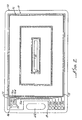
- a thin flexible dielectric substrate 10 formed of a polyamide or polyester, having a thickness not greater than about 1 mil (about 25 microns), is formed with a plurality of bond pads 12a-12e, a plurality of program pads 14a-14e, and a die bond site 46.
- the substrate is generally rectangular in configuration, having a dimension of about 2 inches by 3 1/2 inches, with a rebated or notched portion 18 formed in a short edge thereof.
- An elongated slot 20 is formed in a central portion of the substrate and has one of its ends adjacent a via 22 that extends through the substrate.
- a second or outer via 24 extends through the substrate adjacent the bond pads 12a-12e.
- a first antenna coil 26 wound in a clockwise direction, as viewed in FIG. 1, from a connection of one end of the coil to the via 22 to a connection of the other end of the coil at a point 30 to one of the bond pads, such as pad 12b.
- An identical coil is formed on the obverse side of the substrate 10 with an inner end 32 connected by means of via 22 to the end 23 of the first coil 26, and has an outermost end 38 that is connected to the outer via 24 on the obverse side of the substrate 10. The turns of the two coils are precisely aligned and are in registration with one another.
- the two coils are connected in series and wound continuously in a single direction, which is clockwise, for example, as considered when starting from end 38 of the second coil 31 and following this coil around to its inner end 32, thence to the inner end of the second coil 23 at via 22 and continuing in a clockwise direction to the outer end 30 of coil 26.
- the precise alignment and mutual registration of the two coils and their close proximity to one another, being separated only by the very thin 1 mil thickness of the dielectric, provides for high mutual inductance and self capacitance.
- a plurality of connecting leads 40 connect the five programming pads 14a-14e to the five bond pads 12a-12e.
- These program connecting leads include a lead 70b (FIG. 3) that connects to the outer via 24 on the near or first side of the substrate 10.
- a die bond site 46 is formed on the first side of the substrate at one corner adjacent the bond pads 12a-12e.
- a die 50 (see FIG. 3), not shown in FIGS. 1 and 2, is mounted on the die bond site.
- the capacitance between the two closely spaced coils may be augmented by a capacitor chip mounted on the substrate adjacent the bond pads and die bond site. The capacitor would be connected in parallel across the antenna (see FIG. 4) .
- first and second protective plastic layers or covers 58,60 each having a configuration similar to the overall rectangular configuration of the substrate but being larger in each dimension.
- the two plastic covers which may be a PVC material, are bonded to one another under heat and pressure so that the perimetrical edges of the plastic covers which extend beyond the area of the enclosed or sandwiched substrate 10 will flow to and adhesively bond to one another.
- the covers 58,60 will also flow to and adhesively bond to one another at central areas of the covers, generally indicted by dotted line 64 in FIG. 1, which effectively flow through the interior slot 20 formed in the substrate 10.
- the two PVC covers are fixedly secured to one another around the entire perimeter of the device and also over an area of the interior portion of the device.
- the covers which may be a PVC, for example, do not generally adhere to either the dielectric substrate 10, the conductive leads or pads formed on its surface, nor to thin protective layers (not shown in FIG. 1) that may be formed over the leads and pads.
- the layers 58,60 are adhered to one another solely at their outer perimeter, there would be a tendency for the two layers to detach from one another, particularly as the entire device is intentionally made very thin and relatively flexible.
- the centrally located bonded interconnection between the two covers 58,60 greatly decreases any tendency of the protective layers to delaminate.
- FIG. 3 illustrates one form of mounting of a die on the die bond site 46.
- the latter is formed as a thin rectangular sheet of relatively stiff material, such as a copper or other metal, slightly larger than and of the same configuration as the die 50.
- the die is adhesively secured to the bond site 46, and its die pads 64a-64e are connected respectively to the bond pads 12a-12e by suitable means, such as wire bonds 66a-66e.
- the programming pads 14a-14e are connected to the respective bond pads by means of leads 70a-70e, inclusive.
- a final outer turn 72 of near side antenna coil 26 extends vertically (as viewed in FIG. 3) and includes a portion 74 which extends around the bond pad 12a for connection to bond pad 12b.
- One of the programming leads 70a-70e namely lead 70b which interconnects programming pad 14d with bond pad 12d, connects to the end of via 24 on the first side of the substrate. Accordingly, the end of the antenna coil 31 on the observe side of the substrate is connected to the die by means of the via 24, bond pad 12d, and wire bond 66d. The outermost end of the coil 26 on the near side of the substrate is connected by means of the portion 72 of its connecting lead to bond site 12b, which is connected to the die pad by wire bond 66b. If the self capacitance of the two coils is not sufficient, an additional capacitor 15 is mounted on the substrate near the die bond site and connected across the antenna by connection to bond sites 12b and 12d, as illustrated in FIG. 3. The die is located at a corner of the transponder assembly, rather than at some interior position, because the corners of the very flexible transponder cared are less subject to bending. Repeated bending could be detrimental to the die and its connections.
- the described transponder may be made by any suitable well-known flex circuit fabrication techniques, including photolithography or various forms of subtractive (etching) or additive formation of circuitry.
- an additive formation of circuitry which involves the electroforming or other deposition of the various circuit elements on the dielectric substrate.
- the substrate may be seed coated with nickel or copper, or the like. After forming the desired pattern by electroplating on top of the seed layer,the seed layer between circuit traces is flash etch removed.
- Other additive processes can be used; the "shadow” and "bayer” processes are examples. Any of these processes can be used to adhere copper circuit traces to base substrate material.
- the circuit traces thus formed, form the turns of the coils 26 and 31 on both sides, the wire bond and program pads 12 and 14, and the die bond site 46, all of which are formed of thin electroplated copper, for example, and all formed in the same process step.
- Plated through vias can be formed by pre-drilling the substrate prior to plating.
- the coil lines or turns and line spacing are each in the order of 2 mils or less. Smaller line width and smaller spacing enables the use of a larger number of coil turns on each side of the substrate.
- all of the coil turns may be grouped in relatively small narrow perimetrical areas extending around the outer edges of the substrate (as will be described below in connection with FIG. 8), thereby leaving a relatively large area within the center of the substrate that is free of all coil turns.
- a larger number of magnetic flux lines may be encompassed by each of the coils.
- Such an arrangement of grouping coil turns in relatively narrower bands around the outer edges of the substrate and leaving a large interior area free of coil turns can significantly increase performance of the transponder, increasing read range and sensitivity.
- line thicknesses decrease, so that a 2 mil line, for example, may have a thickness in the order of about 0.35 mils. If the turns are too great in number and too small in cross-section, resistance of the coil increases significantly, and thus there is a tradeoff between minimizing line width to obtain desirably increased numbers of lines and coil turns and undesirably increased coil resistance.
- a given number of turns of relatively wide lines covering the entire area of the substrate does not yield as good a performance as does the same number of turns of smaller width lines (and smaller width spaces between lines) that are grouped together near edges of the substrate, thereby leaving a larger area at the interior of the substrate free of coil turns.
- Grouping of the turns near the substrate edges with a free area at the interior, as illustrated in FIG. 8, provides better performance in reading range and greater energy transfer from the exciting field to the coil.
- a larger area for bonding the PVC outer covers in the middle results.
- the desired pattern of narrow lines and pattern of pads and die bond site are electroplated or otherwise electroformed on the thin polyamide, polyester or other flexible nonconductive substrate on the substrate as a first step.
- the coil turns, as previously described, are in registration from front to back, so that distributed self-capacitance and self-inductance occurs from one side of the substrate to the other, with the coil portions on opposite sides being connected to one another by the vias.
- the latter are also coated with the metal of the lines, which may be copper or aluminum.
- the coils are connected in series and wound in an aiding relation.
- a greater increase in mutual coupling and total inductance may be obtained by using a still thinner (less than 1 mil) substrate.
- a preferred substrate is an adhesiveless laminate material (a polyimide clad with copper on both sides), so that there is no additional thickness of adhesive added between the planar coils.
- the coils, pads and bond site are formed from the copper cladding.
- the preferred coil turns and spaces are as narrow as possible and grouped toward the outer perimeter of the substrate to leave a large unobstructed free area at the interior of the substrate.
- the die 50 is mounted on the die site 46 with a suitable adhesive.
- Various types of die mounting and connection are available, including wire bonding (shown in FIG. 3 and described above) and flip-chip mounting (shown in FIG. 9 and to be described below). Illustrated in FIG. 3 is a wire bonding connection in which wire bonds 66a-66e are employed to interconnect the die pads with the bond pads.
- a thin protective coating (now shown) is applied to both top and bottom of the structure prior to the mounting of the die.
- a hole or rebated portion is left in this protective coating to leave the die bond site, bond pads and program pads free of the protective coating until after the die is mounted and connected.
- an epoxy encapsulation (now shown) is applied over the die, the wire bonds and the bond pads for protection and rigidifying of the die and its wire bonds.
- the die is back-lapped prior to mounting.
- the die is ground or otherwise treated to decrease its thickness from a manufactured thickness in the order of about 20 mils to a decreased thickness of about 10 to 12 mils. Any smaller thickness of the die could result in a die too brittle to withstand any significant handling or use.
- the die is programmed by direct electrical contact of a programming apparatus (not shown) with the programming pads 14a-14e that are provided adjacent one edge of the substrate.
- a programming apparatus not shown
- the programming pads 14a-14e that are provided adjacent one edge of the substrate.
- an unique number or other identification is written into and fixed in the die memory to be read out for identification upon interrogation by an energizing exciter RF Signal.
- these programming pads may be cut off, together with appropriate portions of the substrate, after the programming is accomplished to reduce overall size of the structure and to prevent disturbance of the die by ESD (electrostatic discharge).
- ESD electrostatic discharge
- the two outermost protective layers 58,60 are applied to the substrate with its coils, die and pads, and are pressed together at a suitably high temperature to cause the material of the outer protective layers to soften and flow together, thereby adhesively bonding the two outer laminates 58,60 securely to one another continuously around outer edges of the protective layers and also at central portions thereof through the slot 20 in the substrate 10.
- the two outermost layers 58,60 of course also bond to one another through the rebated portion 18 of the substrate, leaving the mutually registering slots 61a and 61b to extend through the finished product for reception of a securing strap or the like.
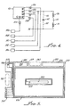
- FIG. 4 shows an electrical schematic diagram of the transponder of FIGS. 1 through 3, illustrating the two series wound coils 26,31 connected to one another by means of via 22, and connected at opposite ends thereof to contact pads on die 50 through bond pad 12b for coil 26 and through via 24 and bond pad 12d for coil 31.
- the five programming pads 14a-14e are connected to the bond pads 12a-12e, which are connected by wire bonds to the die contact pads, as described above.
- programming pads 14b and 14a are used for application of minus and plus AC respectively.
- Pad 14a is used for program voltage ground, pad 14c, for program voltage, and pad 14e for a negative DC connection.
- the unconnected die pad contact may be employed for test purposes.
- capacitor 52 that may be connected by means of leads 54,56 across the ends of the series connected antenna coils 26,31 to provide additional capacitance when necessary.
- the capacitor 52 may be in the form of a chip capacitor or film capacitor 15 (see FIG. 3) mounted on the substrate adjacent the die bonding site. Additional capacitance may alternatively be provided by use of parallel plate capacitors mounted in the manner illustrated in FIG. 5 and described below.
- FIG. 5 Illustrated in FIG. 5 is a modified form of identification transponder card which is modified to incorporate a second carrier strap slot and a pair of parallel plate capacitors.
- FIG. 5 illustrates only the substrate and components mounted on one side of the substrate. Omitted from the showing of FIG. 5 are the outer protective laminates, interior protective coatings, and the obverse side coil, all of which are the same as corresponding elements of the transponder of FIGS. 1 - 3.
- Components of the transponder of FIG. 5 that are the same as corresponding components of FIGS. 1 - 3 are designated by the same reference numerals augmented by 300, so that, for example, substrate 310 of FIG. 5 corresponds to substrate 10 of FIGS. 1 - 3.
- a substrate 310 which may be substantially identical except for slight changes in configuration to the thin substrate 10, is formed with an interior slot 320 and a through via 322 which is connected to one end of a near side antenna coil 326. Also formed on the substrate are a die bond site 346, a plurality of bond pads 312, and a plurality of program pads 314 interconnected by a group of connecting leads 370.
- the several electrical components including an observe side coil (not shown in FIG. 5), are connected in the manner described above in connection with the transponder card shown in FIGS. 1 through 4.
- the substrate is rebated, as at 308, to allow for formation of a first carrier slot 361 (shown in dotted lines in FIG. 5) that is to be formed in the outer protective laminates (not shown in FIG. 5).
- a second rebated portion 319 that allows for the formation of a second carry strap slot 363 to be formed in the outer protective laminates (not shown in FIG. 5).
- the provision of the pair of slots gives flexibility of use to the card user.
- substantially rectangular copper capacitor plates 334,336 that are electroplated on the substrate 310 together with the electroplating of the other circuit elements.
- corresponding mating and aligned halves of capacitor plates 334,336 are formed on the obverse side of the substrate so that plate 334, together with its mating half on the obverse side, and also plate 336, together with its mating half on the obverse side, each forms a separate parallel plate capacitor separated only by the very small thickness of the thin substrate 310.
- These capacitors also may be connected in series or parallel across the antenna coil as desired, thereby adding additional capacitance, if coil self-capacitance is considered to be insufficient.
- the antenna coils cover an area of the substrate that extends nearly to the right and bottom substrate edge (as seen in FIG. 5) and nearly to the inner edges of rebated areas 315,319 at the left and top, closely circumscribing interior slot 320.
- the transponder illustrated in FIGS. 1 through 4 and described above is specifically designed for use as a personal identification card that is to be placed near but not in contact with an exciter and which will transmit to the exciter information identifying the specific identification card and the person holding it.
- transponders of this type is its use as a laundry tag for identification of specific pieces of clothing.
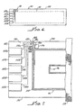
- Such a laundry tag transponder is illustrated in FIGS. 6 and 7 as including a substrate 90 of the same thickness and material as the substrate of the prior embodiment but is smaller, having a relatively long narrow shape that is more readily bonded to a piece of clothing.
- the substrate which may be formed of an adhesiveless laminate (copper on each side of a 1 mil polyimide substrate) or polyimide or polyester of 1 mil thickness has a length of about 3.6 inches and a width of 1 inch.
- An antenna coil 95 is formed on the substrate (as by etching the copper cladding), covering an area indicated by dotted line 94 in FIG. 6.
- a similar antenna coil (now shown in FIG. 6) is wound on the other side of the substrate, and, just as in the previously described embodiments, the two coils have interior end portions thereof connected through a via, such as via 96, extending through the substrate and have their turns in precise alignment and mutual registration on opposite sides of the substrate to provide improved mutual inductance and capacitance.
- Both coils are wound in the same direction when viewed from the near side.
- a plurality of bond pads 98a-98e are formed at an area adjacent one long edge 100 of the substrate and spaced inwardly a significant distance from a short edge 102 of the substrate.
- a major portion of the area of the substrate adjacent short edge 102 is occupied by a plurality of programming pads 102a-102e, each of which is formed with an outermost edge extending to the edge 102 of the substrate, for reasons to be described below.
- a die site 106 Positioned inwardly of the bond pads is a die site 106 on which is mounted a die 108 having a plurality of die pads 110a-110e that are connected by wire bonds 112a-112e to the respective bond pads.
- a group of leads 114a-114e interconnects the bond pads with the inner sides of the program pads.
- a second via 120 extends through the substrate for connection to an end of the antenna coil (not shown) that is wound on the obverse side of the substrate.
- An end portion 122 of the near side coil 95 is connected to bond pad 98e, and the inner end of the coil 95 is connected to the via 96, and by means of such via is connected to the inner end of the corresponding coil on the obverse side of the substrate.
- the second via 120 extends through the substrate at a point connected to lead 114b that interconnects bond pad 98b with program pad 102b.
- the program pads are generally elongated in the direction of the length of the laundry tag, having shorter dimensions in the direction of the short edge of the substrate so as to enable closer spacing of the program pads in this transverse direction.
- the fabrication process of the described laundry tag is generally the same as the fabrication process described in connection with the personal identification card of FIGS. 1 through 3.
- the antenna coils on both sides, the die bond site, the bond pads and the programming pads and all interconnecting leads are formed preferably by additive processes on the one side of the substrate that is visible in FIG. 3.
- the antenna coil is formed on the obverse side.
- the two vias, previously drilled, are conductively plated in this same step.
- the coils on both sides are covered with a thin layer 131 of a protective dielectric. This may be a conventional etchant maskant applied in liquid form. Alternatively, a layer of Kapton about 1 mil thick is adhered to the substrate and coils with a suitable adhesive.
- the Kapton or other liquid maskant protective layer is arranged to cover the entire obverse side of the substrate, including the coils and vias on such obverse side.
- the Kapton covers only the innermost edge of the programming pads, that is, the interior edge portion to the right of a line indicated at 130 in FIG. 7, and also covers the various leads 114, but does not cover the die bond site nor the bond pads on the near side.
- the Kapton coating accordingly, leaves outermost portions of each of the programming pads exposed for a length (in the direction of the length of the elongated laundry tag) of approximately 0.21 inches.
- Each programming pad in a particular example, has a length of approximately 0.230 inches and a width of 0.130 inches, being spaced apart by a distance of 0.030 inches.
- the bond pads and the programming pads may be flash plated with a thin layer of nickel and gold for wire bonding and environmental stability, respectively.
- Die 108 is then adhesively mounted upon and secured to the die bond site 106, and the several wire bonds are formed connecting the pads on the die with the bond pads. After completing the wire bonding of the die pads, the entire area around the die and including the bond pads and the wire bonds are sealed with a suitable epoxy.
- the height of the epoxy and the height of the wire bonds is minimized to maintain a minimum thickness of the finished product.
- the laundry tag program pads 102a-102e are connected to suitable programming circuitry to program the die with the desired identification information, which may simply be a specific identification number. After this programming, both sides of the entire end of the substrate, including the outer ends of the program pads up to the line 130, is cut off. Thus the length of the laundry tag is decreased for ease of use and exposed portions of program pads are eliminated.
- the programmed laundry tag with both sides completely covered by a thin protective coating 131 now has a heat bondable adhesive bonded to one side (the obverse side as seen in the drawings) and the entire tag is heat bonded to a garment that will be identifiable by this tag. Finally a strip of cloth 133 slightly larger than the tag is placed over the entire tag and heat bonded along its periphery. For use in identification of an individual piece of clothing, the cloth laundry tag is then thermally bonded to a garment by the final cloth strip 133, preferably at a laundry which is set up to process and maintain control and identification of numbers of such garments.
- the laundry tag with its several layers, substrate 100, coils 94 and 97, outer dielectric protective layer 131, inner dielectric protective layer 135, and heat bendable inner adhesive layer 137, is first bonded to a garment 141, and then covered with the cloth strip 133 which is bonded to the garment around the periphery of the tag.
- FIG. 9 Such a transponder arrangement is schematically shown in FIG. 9 wherein a substrate 160 is formed with rebated portions 162,164 along one long and one short edge to accept one or the other of the carry strap slots formed in the transponder protective PVC laminate covers (not shown).
- An antenna coil 166 (and a corresponding coil (not shown) on the obverse side) has its turns bunched in a narrow area around the substrate edge, as indicated by lines 168,169 that represent outer and inner coil boundaries.
- Bond pads 170, die site 172 and program pads 174 are formed on the substrate as previously described.
- a slot 175 to allow mutual bonding to the two outermost protective PVC laminates (not shown) is formed in the unoccupied center area 176, within the coil.
- This area may mount parallel plate capacitors (not shown in FIG. 9) if needed for resonance, where the coils self-capacitance is not sufficient.
- This arrangement is closer to an air wound coil in performance, and preferably uses coil turns having a width of one to two mils with one to two mil turns spacing.
- the die may be a pre-programmed die so that a specific identification number is programmed into the die during the manufacture of the die. Accordingly, with use of this type of die no program pads are needed on the transponder.
- a pre-programmed die, used in a transponder with no program pads may be used in various types of arrangements, including use as a laundry tag. In a laundry system it is only necessary that the different transponders or tags have individually unique numbers or other identifying indicia, and it may not be necessary or desirable for the laundry operator to be able to select individual identifying numbers for programming into the specific tags.
- identification transponder In a personal identification transponder, on the other hand, it is often desirable for a specific company or organization that uses identification cards for its employees to insert its own identification system into the die.
- identification systems may include not only an individual employee identification number, but also a facility, building, room number, or group of room numbers to which access may be specifically controlled by the transponder, such that only those transponders with a particular room or facility number would be allowed access.
- the die bond sites formed of a sheet of metal, such as copper, of a generally rectangular shape or other configuration, provide desirable stiffening of that portion of the very thin and highly flexible substrate at which the die is mounted.
- the die bond site physically stabilizes and stiffens the area including the die and the bond pads. Thus, with such stiffening, there is less flexing of the various leads at this portion of the circuit where connections are made, and less flexing of the wire bond.
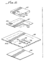
- FIG. 7 illustrates only a corner portion of a substrate with its die mounting site and bond pads, but does not show the antenna coils and the remainder of the transponder structure which otherwise may be identical to the transponders previously described.
- a substrate 200 which may be a polyamide, polyester of very small thickness, such as 1 mil or the like, has a die bond site 202 secured to one surface thereof in the area indicated by the dotted line 202a.
- the die bond site is generally rectangular, having a rebated portion or recess 204 that is cut away to encompass a pair of die connecting pads 208,210 shown in dotted lines at a lower surface of a die 212.
- the two die pads are spaced close to one another and positioned at one corner of the die.
- Die bond pad 216 is connected by a lead 222 to a via 224 that extends through the substrate for connection to an end of an antenna coil (not shown) formed on the obverse side of substrate 200.
- a lead 226 connects die bond pad 220 to an end of the antenna coil (not shown) on the near side of the substrate.
- a third or die support pad or support leg 230 is formed directly on the die bond site 202a to provide a third stabilizing support leg for the flip-chip mounting of the die 212.
- the die support pad 230 performs no electrical function, but is provided solely for physically stabilizing the die mounting.
- the third support helps to level the die to ensure a space between the die and bond site for application of die bonding epoxy.
- the metal die bond site 202 provides a stiffening for a portion of the thin, flexible substrate.
- This stiffening is enhanced in the described arrangement by a second metallic stiffening sheet 234 having dimensions substantially the same as dimensions of the near side die site 202 but having no rebated portion.
- the obverse side stiffening sheet 234 is formed on and securely bonded to the obverse side of the substrate in alignment and registration with the die site stiffening sheet 234.
- the die is flip-chip mounted by positioning the die over the die site 202 with its die contacts 208,210 in direct engagement with the die bond pads 216,220 on the substrate.
- the die support pad 230 is formed upon the die bond site 202 so as to contact an underside of the die that is spaced from the two die contact pads.
- the area between the die bond pads and the die support pad 230 may have a height above the substrate in the order of 1 to 2 mils, and the space between the die bond site 202 and the die is filled with a suitable rigidifying electrically nonconductive epoxy that stabilizes the die to the bond site and that adhesively secures the die to the die site.
- the stiffening die bond site 202, the stiffener 234, the die bond pads 216,220 and the die support leg 230, together with the leads 222,226 and the two antenna coils on opposite sides of the substrate are all formed by suitable, preferably additive, processes, such as those described above.
- the antenna coils, but not the die bond pads may be coated with a thin layer of liquid dielectric or Kapton, and the entire obverse side including stiffener 234 may also be coated similarly.
- suitable electrically nonconductive epoxy After the mounting of the die on the substrate the die and immediately adjacent areas are encapsulated with suitable electrically nonconductive epoxy.
- the entire assembly is then laminated between a pair of polyvinylchloride protective layers, as with the previously described personal identification card, or may be covered with a cloth, as described above in connection with use as a laundry tag.
- the arrangement illustrated in FIG. 10 provides greatly improved stiffening in the area of the die mounting and in the area at which the connections are made between the antenna coils and the bond pads.
- the substrate is made of a very thin material to allow the two coils on its opposite sides to be positioned very close to one another, and the two coils are positioned in alignment and registration so as to improve inductance and capacitance.
Landscapes
- Engineering & Computer Science (AREA)
- Physics & Mathematics (AREA)
- Theoretical Computer Science (AREA)
- General Physics & Mathematics (AREA)
- Microelectronics & Electronic Packaging (AREA)
- Computer Hardware Design (AREA)
- Computer Networks & Wireless Communication (AREA)
- Health & Medical Sciences (AREA)
- Toxicology (AREA)
- Electromagnetism (AREA)
- General Health & Medical Sciences (AREA)
- Artificial Intelligence (AREA)
- Computer Vision & Pattern Recognition (AREA)
- Near-Field Transmission Systems (AREA)
- Details Of Aerials (AREA)
Claims (27)
- Verfahren zur Herstellung eines Hochfrequenz-Indentifikationstransponders, das die Schritte aufweist:Ausbilden eines dünnen dielektrischen Substrats (10, 200, 90, 310, 160) aus einer Schicht flexiblen Materials mit einer Dicke von nicht mehr als etwa fünfundzwanzig Mikrometern und mit einer ersten und einer zweiten Seite,Ausbilden eines Plättchenbefestigungsstandorts (46, 106, 202, 346, 172) einschließlich einer Schicht aus steifem Material, das die erste Seite überlagert,Ausbilden einer Mehrzahl von Verbindungsanschlüssen bzw. Kontaktflächen (12a - 12e, 98a - 98e, 216, 220, 170, 312) auf der ersten Seite neben dem Plättchenbefestigungsort,Ausbilden einer ersten mehrfach gewundenen flachen Antennenspule (26, 326, 95, 94) auf der ersten Seite mit einem ersten Ende an einem inneren Abschnitt des Substrats und mit einem zweiten Ende an einer der Verbindungskontaktflächen,Ausbilden eines ersten Vias (22, 322, 96), das sich durch das Substrat erstreckt und mit dem ersten Ende auf der ersten Seite des Substrats verbunden ist,Ausbilden eines zweiten Vias (24, 120) durch das Substrat neben einer der Verbindungskontaktflächen,Ausbilden einer zweiten Antennenspule (31, 97) mit mehreren Windungen auf der zweiten Seite des Substrats mit einem ersten Ende an einem inneren Abschnitt des Substrats, das mit dem ersten Via verbunden ist und mit einem zweiten Ende, das mit dem zweiten Via verbunden ist auf der zweiten Seite des Substrats,Verbinden des zweiten Vias auf der ersten Seite des Substrats mit einer der Verbindungskontaktflächen,Montieren eines Plättchens (50, 105, 212) auf dem Substrat an dem Plättchenbindungsort undelektrisches Verbinden des Plättchens mit den Verbindungskontaktanschlüssen.
- Verfahren nach Anspruch 1, einschließlich der Schritte des Bildens einer Mehrzahl von Programmierungskontaktflächen (14a - 14e, 314, 102a - 102e, 174) auf der ersten Seite und des Ausbildens einer Mehrzahl von Programmierleitungen (70a - 70e, 3170, 114a - 114e) auf der ersten Seite, die Programmierkontaktflächen und Verbindungskontaktflächen (12a - 12e, 98a - 98e, 216, 220, 170, 312) miteinander verbinden.
- Verfahren nach Anspruch 2, wobei der Schritt des Ausbildens des zweiten Vias (24, 120) das Ausbilden des zweiten Vias bei einer Position auf dem Substrat beinhaltet, die eine Verbindungsleitung (40, 122) zwischen einer der Verbindungskontaktflächen und einer der Mehrzahl von Plättchenkontaktflächen (12a - 12e, 98a - 98e, 216, 220, 170, 312) auf dem Plättchen verbindet.
- Verfahren nach Anspruch 3, wobei der Schritt des Ausbildens des Plättchenkontaktortes (46, 106, 202, 346, 172) das Ausbilden der Schicht (46, 202, 234) des steifen Materials als eine metallische Schicht (202) mit einer Ausnehmung (204) aufweist, wobei der Schritt des Ausbildens einer Mehrzahl von Verbindungskontaktflächen (12a - 12e, 98a - 98e, 216, 220, 170, 312) das Ausbilden der Kontaktanschlußflächen in einem Muster innerhalb der Ausnehmung (204) der metallischen Schicht aufweist, wobei der Schritt des Montierens eines Plättchens die Schritte aufweist des Bereitstellens eines Plättchens, wobei die Plättchenkontaktflächen (208, 210) neben einer Ecke hiervon und in einem Muster angeordnet ist, das zu dem Muster der Verbindungskontaktflächen paßt, und das Positionieren des Plättchens (50, 108, 212) auf dem Plättchenverbindungsort, wobei die Plättchenkontaktflächen in elektrischem Kontakt mit den Verbindungskontaktflächen sind.
- Verfahren nach Anspruch 4, einschließlich des Schrittes des Ausbildens einer Plättchentragekontaktfläche (230) auf dem Plättchenbefestigungsort (202) für das Tragen, Ausrichten und Stabilisieren des Plättchens (212).
- Verfahren nach Anspruch 1, wobei die Schritte des Ausbildens einer ersten und zweiten Antennenspule (26, 326, 94, 95, 31, 97) das Ausbilden der Windungen der Spule in gleichen Richtungen, wenn sie von einer Seite des Substrats betrachtet werden, und das Ausbilden der Spulen, so daß die Windungen der ersten Spule mit den Windungen der zweiten Spule direkt ausgerichtet und paßgenau sind.
- Verfahren nach Anspruch 1, wobei der Schritt des Ausbildens der ersten und zweiten Spule (26, 326, 94, 95, 31, 97) den Schritt beinhaltet des Ausbildens der Spulenwindungen der ersten und zweiten Spule in einem umkreisenden Bereich, der die inneren Abschnitte des dünnen Substrats begrenzt, wobei ein Abschnitt des Substrats auf sowohl der ersten als auch der zweiten Seite frei von Antennenspulen ist, um einen zentralen spulenwindungsfreien Bereich bereitzustellen.
- Verfahren nach Anspruch 1, wobei der Schritt des Ausbildens des dünnen dielektrischen Substrats (10, 200, 90, 310, 160) das Ausbilden des Substrats als ein Körper von im allgemeinen rechteckiger Konfiguration aufweist, mit einem Paar von gegenüberliegenden kurzen Kanten und einem Paar von gegenüberliegenden längeren Kanten und einschließlich des Schrittes des Ausbildens des Plättchenbefestigungsortes (46, 106, 202, 346, 174) und der Befestigungskontaktflächen (12a - 12e, 98a - 98e, 216, 220, 170, 312) an einer Ecke des Substrats neben einer ersten kurzen Kante, das Ausbilden der Programmierkontaktflächen (14a - 14e, 314, 102a - 102e, 174) auf der ersten Seite an einer gegenüberliegenden Ecke der ersten kurzen Kante und das Positionieren des Plättchenbefestigungsortes und der Verbindungskontaktflächen neben einer langen Kante und nach innen von der ersten kurzen Kante beabstandet, wobei der Schritt des Ausbildens der Programmierkontaktflächen den Schritt der Positionierung der Programmierkontaktflächen näher an der ersten kurzen Kante als an dem Plättchenbefestigungsort und den Befestigungskontaktflächen beinhaltet, das Einsetzen der Programmierkontaktflächen, um das Plättchen (50, 108, 212) zu programmieren und weiterhin den Schritt aufweist des Entfernens eines Endabschnittes des Substrats, der sich entlang der zuerst erwähnten kurzen Kante erstreckt, wobei der Schritt des Entfernens eines Endabschnittes des Substrats den Schritt des Entfernens der am äußersten liegenden Abschnitte der Programmierkontaktflächen beinhaltet.
- Verfahren nach Anspruch 1, wobei die Schicht aus steifem Material eine erste metallisierte steife Schicht (202) ist, und wobei das Verfahren den Schritt beinhaltet des Ausbildens einer zweiten metallisierten steifen Schicht (234) auf der zweiten Seite des Substrats in Ausrichtung mit der ersten metallisierten steifen Schicht (202).
- Verfahren nach Anspruch 3, in dem der Plättchenbefestigungsort (46, 202) eine Ausnehmung (204) hat und wobei die Befestigungskontaktflächen (12a - 12e, 98a - 98e, 216, 220, 170, 312) innerhalb der Ausnehmung des Befestigungsortes positioniert sind, und wobei das Verfahren den Schritt beinhaltet des Befestigens des Plättchens (50, 108, 212) durch Verbinden der Plättchenkontaktflächen (205, 210) direkt mit den Verbindungskontaktflächen, wobei die Verbindungskontaktflächen in einer Konfiguration angeordnet sind, die mit der Konfiguration der Plättchenkontaktflächen übereinstimmt.
- Verfahren nach Anspruch 1, einschließlich der Schritte des Sichems einer ersten Schutzabdeckung (58) auf der zweiten Seite des Substrats über der zweiten Antennenspule (31, 97) und Aufbringen einer zweiten dielektrischen Schutzabdeckung auf die erste Seite des Substrats, die die erste Antennenspule (26, 326, 95, 94), das Plättchen (50, 105, 212) und die Befestigungskontaktflächen (12a - 12e, 98a - 98e, 216, 220, 170, 312) abdeckt (60) und schützt.
- Verfahren nach Anspruch 11, das den Schritt des Ausbildens eines Schlitzes bzw. Slots (20, 175) in einem inneren Abschnitt des Substrats einschließt und wobei der Schritt des Sicherns der ersten Schutzabdeckung (58) und des Aufbringens der zweiten Schutzabdeckung (60) das Verbinden der ersten und zweiten Schutzabdeckungen miteinander entlang des Umfangs des Substrats und durch den Schlitz aufweist.
- Verfahren nach Anspruch 11, wobei der Schritt des Ausbildens des Plättchenbefestigungsortes (46, 106, 202, 346, 172) das Positionieren des Plättchenbefestigungsortes an einer Ecke des dielektrischen Substrats aufweist, wobei der Schritt des Ausbildens erster und zweiter Schutzabdeckungen (58, 60) den Schritt des Ausbildens erster und zweiter Verbindungselementöffnungen an entsprechenden Endabschnitten der Schutzabdeckungen und das Sichem der Abdeckungen mit den ersten Verbindungsmittelöffnungen (61a, 61b) in gegenseitiger Ausrichtung zueinander beinhaltet.
- Verfahren nach Anspruch 8, das den Schritt des Ausbildens einer dielektrischen Schutzschicht über sowohl die erste als auch die zweite Seite des Substrats (10, 200, 90, 310, 160) und über die Antennenspulen (26, 326, 94, 95, 31, 97) beinhaltet.
- Verfahren nach Anspruch 14, wobei der Schritt des Aufbringens der dielektrischen Schutzschicht das Aufbringen der Schutzschicht beinhaltet, um nur die innersten Abschnitte der Programmierungskontaktflächen (14a - 14e, 314, 102a - 102e, 174) gegenüber den Verbindungskontaktstellen (12a - 12e, 98a - 98e, 216, 220, 170, 312) abzudecken, wobei der Schritt der elektrischen Verbindung der Programmierkontaktflächen mit den Verbindungskontaktflächen das Verbinden der inneren Seiten der Programmierkontaktflächen aufweist, wobei der Schritt des Entfernens eines äußersten Abschnittes des Substrats den Schritt des Entfernens der äußersten Abschnitt der Programmierkontaktflächen, die nicht durch die Schutzschicht abgedeckt sind, aufweist, wobei alle verbleibenden Abschnitte der Programmierkontaktflächen durch die Schutzschicht abgedeckt werden.
- Hochfrequenz-Identifikationstransponder, der aufweist:ein dünnes dielektrisches Substrat (10, 200, 90, 310, 160), das aus einer Schicht aus flexiblem Material mit einer Dicke von nicht mehr als etwa fünfundzwanzig Mikrometern hergestellt ist, und eine erste und zweite Seite hat, wobei die erste Seite einen Plättchenbefestigungsort (46, 106, 202, 346, 172) und eine Mehrzahl von Befestigungskontaktflächen (12a - 12e, 98a - 98e, 216, 220, 170, 312), die hierauf neben dem Plättchenfestigungsort ausgebildet sind, hat, wobei der Plättchenbefestigungsort (46, 106, 202, 346, 172) eine Schicht aus steifem Material hat, das zumindest eine Seite des Substrats überlagert,eine erste flache Antennenspule (26, 326, 95, 94) mit mehreren Windungen auf der ersten Seite mit einem ersten Ende an einem inneren Abschnitt des Substrats und mit einem zweiten Ende, das mit einer der Verbindungskontaktflächen verbunden ist,ein erstes Via (22, 322, 96), das sich durch das Substrat erstreckt und mit dem ersten Ende auf der ersten Seite des Substrats verbunden ist,ein zweites Via (24, 120), das sich neben den Verbindungskontaktflächen durch das Substrat erstreckt,eine zweite flache Antennenspule (31, 97) mit mehreren Windungen auf der zweiten Seite des Substrats mit einem ersten Ende an einem inneren Abschnitt des Substrats, das mit dem ersten Via verbunden ist, und mit einem zweiten Ende, das mit dem zweiten Via auf der zweiten Seite des Substrats verbunden ist,eine elektrische Leitung (40, 222), die das zweite Via auf der ersten Seite des Substrats mit einer der Verbindungskontaktflächen verbindet, undein Plättchen (50, 108, 212), das auf dem Plättchenbefestigungsort montiert ist und elektrisch mit den Befestigungskontaktflächen verbunden ist.
- Hochfrequenz-Identifikationstransponder nach Anspruch 16, wobei das steife Material (46, 202, 234) des Plättchenbefestigungsortes eine metallisierte Schicht ist, die in ihrer Größe im wesentlichen mit dem Plättchen übereinstimmt.
- Hochfrequenz-Identifikationstransponder nach Anspruch 16, wobei die Antennenspulen (26, 326, 94, 95, 31, 97) auf der ersten und zweiten Seite des Substrats, von einer Seite des Substrats betrachtet, in gleiche Richtungen gewunden sind, und wobei zumindest ein Hauptteil der Windungen der ersten Spule in direkter Ausrichtung und Paßgenauigkeit mit den Windungen der zweiten Spule ist.
- Hochfrequenz-Identifikationstransponder nach Anspruch 16, wobei die Spulenwindungen der ersten und zweiten Spule (26, 326, 94, 95, 31, 97) in einem Umgebungsbereich positioniert sind, der die inneren Abschnitte des dünnen Substrats umgrenzt, wobei ein Abschnitt des Substrats auf sowohl der ersten als auch der zweiten Seite frei von Antennenspulen ist, um einen zentralen Bereich, der frei von Spulenwindungen ist, bereitzustellen.
- Hochfrequenz-Identifikationstransponder nach Anspruch 16, wobei die Schicht (46, 202) aus festem Material eine erste dünne Metallschicht ist, die mit der ersten Seite an einem Bereich der ersten Seite montiert ist, wo das Plättchen montiert ist, und der Plättchenbefestigungsort weiterhin eine zweite dünne Metallschicht (234) beinhaltet, die mit einem Abschnitt der zweiten Seite in dem Bereich des Plättchens und der Verbindungskontaktflächen auf der ersten Seite verbunden ist und diese abdeckt.
- Hochfrequenz-Identifikationstransponder nach Anspruch 16, der weiterhin eine erste Schutzabdeckung (58) aufweist, die an der zweiten Seite des Substrats über der zweiten Antennenspule (31, 97) gesichert ist, und eine zweite dielektrische Schutzabdeckung (60) aufweist, die an der ersten Seite des Substrats gesichert ist und die erste Antennenspule (26, 326, 95, 94) und das Plättchen (50, 108, 212) und die Befestigungskontaktflächen (12a - 12e, 98a - 98e, 216, 22, 170, 312) abdeckt und schützt.
- Hochfrequenz-Identifikationstransponder nach Anspruch 21, wobei das Substrat eine Öffnung (20, 175) an einem inneren Abschnitt hiervon hat, wobei die erste und die zweite Antennenspule (26, 326, 94, 95, 31, 97) frei von der Öffnung sind, wobei die erste und zweite Schutzabdeckung (58, 60) miteinander an den äußeren Kanten hiervon und durch die Öffnung verbunden sind.
- Hochfrequenz-Identifikationstransponder nach Anspruch 21, der eine Mehrzahl von Programmierkontaktflächen (14a - 14e, 314, 102a - 102e, 174) beinhaltet, die auf der ersten Seite des Substrats ausgebildet sind, der eine Mehrzahl von Programmierleitungen (70a - 70e, 370, 114a - 114e) auf der ersten Seite beinhaltet, die die Programmierkontaktflächen mit den Verbindungskontaktflächen (12a - 12e, 98a - 98e, 216, 220, 170, 312) miteinander verbinden, wobei die zweite dielektrische Schutzabdeckung (60) die Programmierkontaktflächen abdeckt und schützt.
- Hochfrequenz-Identifikationstransponder nach Anspruch 23, wobei der Plättchenbefestigungsort (46, 106, 202, 346, 172) an einer ersten Ecke des dielektrischen Substrats positioniert ist und die Programmierkontaktflächen (14a - 14e, 314, 102a - 102e, 174) an einer zweiten Ecke des Substrats positioniert sind, wobei das Substrat einen Abschnitt zwischen dem Plättchenbefestigungsort und der Programmierkontaktfläche gefalzt hat, wobei die erste und zweite Schutzabdeckung (58, 160) zueinander ausgerichtete Befestigungsmittelöffnungen (61a, 61b) beinhaltet, die miteinander und zu dem gefalzten Abschnitt des Substrats ausgerichtet sind.
- Hochfrequenz-Identifikationstransponder nach Anspruch 24, wobei die Schicht aus festem Material (46, 202) auf der ersten Seite positioniert ist.
- Hochfrequenz-Identifikationstransponder nach Anspruch 16, der weiterhin eine dielektrische Schutzschicht über sowohl die erste als auch die zweite Seite des Substrats und über die erste und zweite Antennenspule aufweist, wobei die Schutzschicht an dem Plättchenbefestigungsort (46, 106,. 202, 346, 172) und an den Befestigungskontaktflächen (12a - 12e, 98a - 98e, 216, 220, 170, 312) offen ist, wodurch der Plättchenbefestigungsort und die Befestigungskontaktflächen nicht von der Schutzschicht abgedeckt werden.
- Hochfrequenz-Identifikationstransponder nach Anspruch 26, der eine Schicht aus heiß bondbarem Klebemittel beinhaltet, die auf der dielektrischen Schutzschicht auf der zweiten Seite gesichert ist, und derart konfiguriert und angeordnet ist, um den Transponder an einem Kleidungsstück zu befestigen, und einen Stoffstreifen aufweist, der das Substrat und die dielektrische Schutzschicht auf der ersten Seite abdeckt und derart konfiguriert und angeordnet ist, um den Transponder weiter an dem Kleidungsstück zu sichern.
Applications Claiming Priority (2)
| Application Number | Priority Date | Filing Date | Title |
|---|---|---|---|
| US08/540,785 US5574470A (en) | 1994-09-30 | 1995-10-11 | Radio frequency identification transponder apparatus and method |
| US540785 | 1995-10-11 |
Publications (3)
| Publication Number | Publication Date |
|---|---|
| EP0768620A2 EP0768620A2 (de) | 1997-04-16 |
| EP0768620A3 EP0768620A3 (de) | 2000-02-02 |
| EP0768620B1 true EP0768620B1 (de) | 2004-01-02 |
Family
ID=24156930
Family Applications (1)
| Application Number | Title | Priority Date | Filing Date |
|---|---|---|---|
| EP96306467A Expired - Lifetime EP0768620B1 (de) | 1995-10-11 | 1996-09-05 | Radiofrequenz-Indentifikationstransponder und Verfahren zu seiner Herstellung |
Country Status (5)
| Country | Link |
|---|---|
| US (1) | US5574470A (de) |
| EP (1) | EP0768620B1 (de) |
| CA (1) | CA2185626C (de) |
| DE (1) | DE69631235T2 (de) |
| ES (1) | ES2213767T3 (de) |
Cited By (2)
| Publication number | Priority date | Publication date | Assignee | Title |
|---|---|---|---|---|
| RU2236726C2 (ru) * | 1999-10-28 | 2004-09-20 | Аск | Антенна связи с высокой индуктивностью |
| DE102009005570A1 (de) * | 2009-01-21 | 2010-07-22 | Mühlbauer Ag | Verfahren zum Herstellen einer Antenne auf einem Substrat |
Families Citing this family (210)
| Publication number | Priority date | Publication date | Assignee | Title |
|---|---|---|---|---|
| AU3086392A (en) * | 1991-12-19 | 1993-07-19 | Ake Gustafson | Security sealing device |
| US7158031B2 (en) | 1992-08-12 | 2007-01-02 | Micron Technology, Inc. | Thin, flexible, RFID label and system for use |
| US5751256A (en) * | 1994-03-04 | 1998-05-12 | Flexcon Company Inc. | Resonant tag labels and method of making same |
| DE4410732C2 (de) * | 1994-03-28 | 1997-05-07 | Amatech Gmbh & Co Kg | Verfahren zur Anordnung einer zumindest einen Chip und eine Drahtspule aufweisenden Transpondereinheit auf einem Substrat sowie Chipkarte mit entsprechend angeordneter Transpondereinheit |
| JPH08310172A (ja) * | 1995-05-23 | 1996-11-26 | Hitachi Ltd | 半導体装置 |
| GB2305075A (en) * | 1995-09-05 | 1997-03-26 | Ibm | Radio Frequency Tag for Electronic Apparatus |
| US6075441A (en) | 1996-09-05 | 2000-06-13 | Key-Trak, Inc. | Inventoriable-object control and tracking system |
| GB9601899D0 (en) * | 1996-01-31 | 1996-04-03 | Neopost Ltd | Mailing system |
| US6171714B1 (en) * | 1996-04-18 | 2001-01-09 | Gould Electronics Inc. | Adhesiveless flexible laminate and process for making adhesiveless flexible laminate |
| US6466131B1 (en) * | 1996-07-30 | 2002-10-15 | Micron Technology, Inc. | Radio frequency data communications device with adjustable receiver sensitivity and method |
| US5781112A (en) * | 1997-02-03 | 1998-07-14 | Shymko; Wayne W. | Electronic tagging device for identifying transported products |
| CA2197828C (en) * | 1997-02-18 | 2004-05-04 | Normand Dery | Thin-film antenna device for use with remote vehicle starting systems |
| WO1998053424A1 (en) * | 1997-05-20 | 1998-11-26 | Ronald Barend Van Santbrink | Method for the production of a smart card, smart card and device for the production thereof |
| EP0886232B1 (de) | 1997-06-20 | 2007-09-05 | Hitachi, Ltd. | Schreib-/Lesevorrichtung, Stromversorgungssystem und Kommunikationssystem |
| US6339385B1 (en) | 1997-08-20 | 2002-01-15 | Micron Technology, Inc. | Electronic communication devices, methods of forming electrical communication devices, and communication methods |
| US5982284A (en) * | 1997-09-19 | 1999-11-09 | Avery Dennison Corporation | Tag or label with laminated thin, flat, flexible device |
| WO1999017261A1 (en) * | 1997-09-29 | 1999-04-08 | Advanced Technology Communications Limited | Security devices |
| FR2769389B1 (fr) * | 1997-10-07 | 2000-01-28 | Rue Cartes Et Systemes De | Carte a microcircuit combinant des plages de contact exterieur et une antenne, et procede de fabrication d'une telle carte |
| US5973599A (en) * | 1997-10-15 | 1999-10-26 | Escort Memory Systems | High temperature RFID tag |
| FR2771233B1 (fr) * | 1997-11-18 | 2000-01-28 | Sgs Thomson Microelectronics | Bobine d'antenne a champ electrique reduit |
| DE19753174A1 (de) * | 1997-11-20 | 1999-10-21 | Diehl Ident Gmbh | Magnetische Antenne für ein Transponder-Kommunikationsgerät |
| US6215402B1 (en) * | 1998-03-13 | 2001-04-10 | Intermec Ip Corp. | Radio frequency identification transponder employing patch antenna |
| GB2333207B (en) * | 1998-01-09 | 2003-06-11 | Peter George Milton | Monitoring reels of paper for use on printing presses |
| US6047579A (en) * | 1998-04-17 | 2000-04-11 | The Minster Machine Company | RF tag attached to die assembly for use in press machine |
| US6118377A (en) * | 1998-06-09 | 2000-09-12 | Flex Products, Inc. | Conductive security article with detector apparatus |
| US6031457A (en) * | 1998-06-09 | 2000-02-29 | Flex Products, Inc. | Conductive security article and method of manufacture |
| DE29814277U1 (de) * | 1998-06-23 | 1999-11-04 | Meto International GmbH, 69434 Hirschhorn | Sicherungselement für die elektronische Artikelsicherung |
| ES2270549T3 (es) * | 1998-06-23 | 2007-04-01 | Meto International Gmbh | Elemento de identificacion. |
| US6087940A (en) * | 1998-07-28 | 2000-07-11 | Novavision, Inc. | Article surveillance device and method for forming |
| US6195005B1 (en) * | 1998-09-11 | 2001-02-27 | Key-Trak, Inc. | Object carriers for an object control and tracking system |
| AU5916799A (en) * | 1998-09-11 | 2000-04-03 | Key-Trak, Inc. | Object tracking system with non-contact object detection and identification |
| AU5924599A (en) | 1998-09-11 | 2000-04-03 | Key-Trak, Inc. | Tamper detection and prevention for an object control and tracking system |
| US6232876B1 (en) * | 1998-09-11 | 2001-05-15 | Key-Trak, Inc. | Mobile object tracking system |
| US6891473B2 (en) * | 1998-09-11 | 2005-05-10 | Key-Trak, Inc. | Object carriers and lighted tags for an object control and tracking system |
| CA2343412A1 (en) * | 1998-09-11 | 2000-03-23 | William C. Maloney | Object control and tracking system with zonal transition detection |
| DE19842366A1 (de) * | 1998-09-14 | 2000-03-16 | Bsh Bosch Siemens Hausgeraete | Produktpflegekennzeichen für Textilien und Verfahren zu seiner Herstellung |
| FR2784524B1 (fr) * | 1998-10-12 | 2006-07-07 | Dassault Electronique | Antenne perfectionnee, notamment pour un lecteur de badge sans contact |
| US6404643B1 (en) | 1998-10-15 | 2002-06-11 | Amerasia International Technology, Inc. | Article having an embedded electronic device, and method of making same |
| US6100804A (en) * | 1998-10-29 | 2000-08-08 | Intecmec Ip Corp. | Radio frequency identification system |
| FR2786009B1 (fr) * | 1998-11-16 | 2001-01-26 | Gemplus Card Int | Procede de fabrication d'une carte a puce hybride par impression double face |
| US6163260A (en) * | 1998-12-10 | 2000-12-19 | Intermec Ip Corp. | Linerless label tracking system |
| US6381416B2 (en) * | 1999-08-11 | 2002-04-30 | Eastman Kodak Company | Film unit having radio-frequency identification transponder |
| US6262692B1 (en) | 1999-01-13 | 2001-07-17 | Brady Worldwide, Inc. | Laminate RFID label and method of manufacture |
| DE19905886A1 (de) * | 1999-02-11 | 2000-08-17 | Meto International Gmbh | Identifizierungselement und Verfahren zur Herstellung eines Identifizierungselements |
| US8538801B2 (en) * | 1999-02-19 | 2013-09-17 | Exxonmobile Research & Engineering Company | System and method for processing financial transactions |
| US6468638B2 (en) | 1999-03-16 | 2002-10-22 | Alien Technology Corporation | Web process interconnect in electronic assemblies |
| US6288905B1 (en) | 1999-04-15 | 2001-09-11 | Amerasia International Technology Inc. | Contact module, as for a smart card, and method for making same |
| US6353420B1 (en) | 1999-04-28 | 2002-03-05 | Amerasia International Technology, Inc. | Wireless article including a plural-turn loop antenna |
| EP1052595B1 (de) * | 1999-05-14 | 2001-09-19 | Sokymat Sa | Transponder und Spritzgussteil sowie Verfahren zu ihrer Herstellung |
| US8585852B2 (en) * | 1999-06-16 | 2013-11-19 | Vanguard Identification Systems, Inc. | Methods of making printed planar radio frequency identification elements |
| US8654018B2 (en) * | 2005-04-06 | 2014-02-18 | Vanguard Identificaiton Systems, Inc. | Printed planar RFID element wristbands and like personal identification devices |
| FR2795238A1 (fr) * | 1999-06-21 | 2000-12-22 | Valeo Securite Habitacle | Antenne emettrice-receptrice de champ magnetique, notamment pour vehicule automobile |
| FR2795239B1 (fr) * | 1999-06-21 | 2006-07-28 | Valeo Securite Habitacle | Antenne d'emission et/ou de reception de champ magnetique dans un systeme de communication a basse frequence |
| US6247857B1 (en) * | 1999-08-11 | 2001-06-19 | Eastman Kodak Company | Multistage system for processing photographic film |
| US6147662A (en) * | 1999-09-10 | 2000-11-14 | Moore North America, Inc. | Radio frequency identification tags and labels |
| WO2001026180A1 (en) * | 1999-10-04 | 2001-04-12 | Amerasia International Technology, Inc. | Tamper-resistant wireless article including an antenna |
| US6421013B1 (en) | 1999-10-04 | 2002-07-16 | Amerasia International Technology, Inc. | Tamper-resistant wireless article including an antenna |
| GB2355116B (en) * | 1999-10-08 | 2003-10-08 | Nokia Mobile Phones Ltd | An antenna assembly and method of construction |
| US6184846B1 (en) | 2000-02-03 | 2001-02-06 | Marconi Commerce Systems Inc. | Loop conductor antenna for fuel dispenser |
| US6304232B1 (en) | 2000-02-24 | 2001-10-16 | The Goodyear Tire & Rubber Company | Circuit module |
| JP3557990B2 (ja) * | 2000-03-09 | 2004-08-25 | ソニーケミカル株式会社 | 情報記録タグ |
| FR2808127B1 (fr) * | 2000-04-21 | 2003-08-15 | A S K | Antenne de lecteur d'un systeme d'emission/reception sans contact |
| US6806812B1 (en) | 2000-04-26 | 2004-10-19 | Micron Technology, Inc. | Automated antenna trim for transmitting and receiving semiconductor devices |
| US6483473B1 (en) * | 2000-07-18 | 2002-11-19 | Marconi Communications Inc. | Wireless communication device and method |
| US7098850B2 (en) * | 2000-07-18 | 2006-08-29 | King Patrick F | Grounded antenna for a wireless communication device and method |
| US6806842B2 (en) * | 2000-07-18 | 2004-10-19 | Marconi Intellectual Property (Us) Inc. | Wireless communication device and method for discs |
| FR2812427B1 (fr) * | 2000-07-28 | 2003-01-03 | Inside Technologies | Etiquette electronique sans contact pour objet tridimensionnel |
| FR2812482B1 (fr) * | 2000-07-28 | 2003-01-24 | Inside Technologies | Dispositif electronique portable comprenant plusieurs circuits integres sans contact |
| US20030169169A1 (en) * | 2000-08-17 | 2003-09-11 | Luc Wuidart | Antenna generating an electromagnetic field for transponder |
| FR2814574B1 (fr) * | 2000-09-22 | 2003-11-28 | Gemplus Card Int | Etiquette electronique sans contact pour produit a surface conductrice |
| JP2002109491A (ja) * | 2000-09-29 | 2002-04-12 | Sony Corp | Icカード及びその製造方法 |
| FR2815176B1 (fr) * | 2000-10-11 | 2003-01-10 | A S K | Antenne spirale d'emission et/ou reception a coupures |
| US7501954B1 (en) | 2000-10-11 | 2009-03-10 | Avante International Technology, Inc. | Dual circuit RF identification tags |
| US6480110B2 (en) | 2000-12-01 | 2002-11-12 | Microchip Technology Incorporated | Inductively tunable antenna for a radio frequency identification tag |
| US6424263B1 (en) | 2000-12-01 | 2002-07-23 | Microchip Technology Incorporated | Radio frequency identification tag on a single layer substrate |
| US6720930B2 (en) | 2001-01-16 | 2004-04-13 | Digital Angel Corporation | Omnidirectional RFID antenna |
| DE60235225D1 (de) * | 2001-03-02 | 2010-03-18 | Koninkl Philips Electronics Nv | Induktives kopplungssystem mit kapazitiver parallelkompensation der gegenseitigen induktanz zwischen den primär- und sekundärwicklungen |
| US6835412B2 (en) | 2001-05-04 | 2004-12-28 | Micrometal Technologies, Inc. | Metalized dielectric substrates for EAS tags |
| US6606247B2 (en) | 2001-05-31 | 2003-08-12 | Alien Technology Corporation | Multi-feature-size electronic structures |
| US6707381B1 (en) * | 2001-06-26 | 2004-03-16 | Key-Trak, Inc. | Object tracking method and system with object identification and verification |
| US6693541B2 (en) * | 2001-07-19 | 2004-02-17 | 3M Innovative Properties Co | RFID tag with bridge circuit assembly and methods of use |
| EP1291818A1 (de) * | 2001-08-15 | 2003-03-12 | Datamars SA | Transponder |
| DE10149126A1 (de) * | 2001-10-05 | 2003-04-10 | Flexchip Ag | Einrichtung zum Abschirmen eines Transponders, Verfahren zum Herstellen einer entsprechenden Abschirmung, sowie Transponder mit Abschirmung |
| US6724311B1 (en) | 2001-11-09 | 2004-04-20 | B&G Plastics, Inc. | Anti-theft hang tag |
| US6809646B1 (en) * | 2001-12-06 | 2004-10-26 | Applied Wireless Identifications Group, Inc. | Thin implantable RFID transponder suitable for use in an identification badge |
| US6614392B2 (en) | 2001-12-07 | 2003-09-02 | Delaware Capital Formation, Inc. | Combination RFID and GPS functionality on intelligent label |
| US20030135817A1 (en) * | 2002-01-11 | 2003-07-17 | G.E. Information Services, Inc. | Automated method, system and software for storing data in a general format in a global network |
| US7214569B2 (en) | 2002-01-23 | 2007-05-08 | Alien Technology Corporation | Apparatus incorporating small-feature-size and large-feature-size components and method for making same |
| US6962439B2 (en) * | 2002-03-08 | 2005-11-08 | The Bagco, Inc. | Leak resistant tamper evident reclosable plastic bag |
| US6700547B2 (en) * | 2002-04-12 | 2004-03-02 | Digital Angel Corporation | Multidirectional walkthrough antenna |
| EP1978473B1 (de) | 2002-04-24 | 2010-07-14 | Mineral Lassen LLC | Herstellungsverfahren für eine drahtlose Kommunikationsvorrichtung und Herstellungsvorrichtung |
| US7113131B2 (en) * | 2002-05-02 | 2006-09-26 | Micrometal Technologies, Inc. | Metalized dielectric substrates for EAS tags |
| FR2844621A1 (fr) * | 2002-09-13 | 2004-03-19 | A S K | Procede de fabrication d'une carte a puce sans contact ou hybride contact-sans contact a planeite renforcee |
| US20040229560A1 (en) * | 2002-10-10 | 2004-11-18 | Maloney William C. | Methods of tracking and verifying human assets |
| US20040069847A1 (en) * | 2002-10-15 | 2004-04-15 | Chester Kolton | Electronic article surveillance marker assembly |
| KR20040038134A (ko) * | 2002-10-31 | 2004-05-08 | 주식회사 쓰리비 시스템 | 안정된 비접촉 통신수단을 제공하는 콤비형 스마트 카드 |
| US7431436B1 (en) | 2002-11-12 | 2008-10-07 | Vutek, Incorporated | Identification system for inks in printing systems |
| US6909371B2 (en) * | 2002-12-17 | 2005-06-21 | Pitney Bowes Inc. | Method for dynamically obtaining telephone numbers |
| US6882276B2 (en) | 2002-12-17 | 2005-04-19 | Pitney Bowes Inc. | Method for dynamically addressing physical mail |
| FR2850189B1 (fr) * | 2003-01-16 | 2006-09-22 | Tagsys | Detecteur, systeme pour l'identification d'articles et procede de fabrication du detecteur |
| US6997388B2 (en) * | 2003-02-19 | 2006-02-14 | Inksure Rf Inc. | Radio frequency data carrier and method and system for reading data stored in the data carrier |
| US7253735B2 (en) | 2003-03-24 | 2007-08-07 | Alien Technology Corporation | RFID tags and processes for producing RFID tags |
| US6922146B2 (en) | 2003-04-24 | 2005-07-26 | Inksure Rf Inc. | Radio frequency data carrier and system for reading data stored therein |
| JP2004364199A (ja) * | 2003-06-06 | 2004-12-24 | Sony Corp | アンテナモジュール及びこれを備えた携帯型通信端末 |
| WO2005027998A2 (en) | 2003-09-16 | 2005-03-31 | Cardiomems, Inc. | Implantable wireless sensor |
| US8026729B2 (en) | 2003-09-16 | 2011-09-27 | Cardiomems, Inc. | System and apparatus for in-vivo assessment of relative position of an implant |
| FR2861201B1 (fr) * | 2003-10-17 | 2006-01-27 | Oberthur Card Syst Sa | Procede de fabrication d'une carte a double interface, et carte a microcircuit ainsi obtenue. |
| US6824320B1 (en) | 2003-11-05 | 2004-11-30 | Eastman Kodak Company | Film core article and method for making same |
| WO2005086085A1 (en) * | 2004-03-08 | 2005-09-15 | Qtrac Limited | Label |
| WO2005089143A2 (en) * | 2004-03-12 | 2005-09-29 | A K Stamping Co. Inc. | Manufacture of rfid tags and intermediate products therefor |
| WO2005093900A1 (en) * | 2004-03-26 | 2005-10-06 | Semiconductor Energy Laboratory Co., Ltd. | Semiconductor device |
| US7446663B2 (en) * | 2004-04-20 | 2008-11-04 | Alcoa Closure Systems International, Inc. | Method of forming an RF circuit assembly having multiple antenna portions |
| AR048873A1 (es) * | 2004-04-20 | 2006-06-07 | Alcoa Closure Systems Int Inc | Metodo para formar un conjunto de circuito |
| US20060002690A1 (en) * | 2004-07-01 | 2006-01-05 | Eastman Kodak Company | Intelligent media splice |
| US20060065738A1 (en) * | 2004-09-30 | 2006-03-30 | Versic Ronald J | Rfid device and method of manufacture |
| US7452748B1 (en) | 2004-11-08 | 2008-11-18 | Alien Technology Corporation | Strap assembly comprising functional block deposited therein and method of making same |
| US7551141B1 (en) | 2004-11-08 | 2009-06-23 | Alien Technology Corporation | RFID strap capacitively coupled and method of making same |
| US7353598B2 (en) | 2004-11-08 | 2008-04-08 | Alien Technology Corporation | Assembly comprising functional devices and method of making same |
| US7385284B2 (en) | 2004-11-22 | 2008-06-10 | Alien Technology Corporation | Transponder incorporated into an electronic device |
| US7688206B2 (en) | 2004-11-22 | 2010-03-30 | Alien Technology Corporation | Radio frequency identification (RFID) tag for an item having a conductive layer included or attached |
| US20060187057A1 (en) * | 2005-02-09 | 2006-08-24 | San-Lien Yang | Radio frequency label module |
| TWI260864B (en) * | 2005-04-08 | 2006-08-21 | Delta Electronics Inc | Wireless communication module |
| FR2884681B1 (fr) * | 2005-04-15 | 2007-06-22 | St Microelectronics Sa | Antenne pour etiquette electronique |
| EP1908043B1 (de) | 2005-04-28 | 2015-03-25 | ZIH Corporation | Antimikrobielle beschichtung für identifikationsvorrichtungen |
| JP2006341858A (ja) * | 2005-06-07 | 2006-12-21 | Matsushita Electric Ind Co Ltd | 包装商品に対するicタグの装着方法 |
| AU2006262287A1 (en) | 2005-06-21 | 2007-01-04 | Cardiomems, Inc. | Method of manufacturing implantable wireless sensor for in vivo pressure measurement |
| US7542301B1 (en) | 2005-06-22 | 2009-06-02 | Alien Technology Corporation | Creating recessed regions in a substrate and assemblies having such recessed regions |
| CA2614599C (en) * | 2005-07-08 | 2016-02-02 | Jason Kroh | Coupling loop, cable assembly and method for positioning coupling loop |
| US20070031992A1 (en) * | 2005-08-05 | 2007-02-08 | Schatz Kenneth D | Apparatuses and methods facilitating functional block deposition |
| US8179259B2 (en) * | 2005-09-16 | 2012-05-15 | Clevx, Llc | Radio frequency identification system |
| TWI286401B (en) * | 2005-11-01 | 2007-09-01 | Chant Sincere Co Ltd | Broadband antenna apparatus |
| US20070131781A1 (en) * | 2005-12-08 | 2007-06-14 | Ncr Corporation | Radio frequency device |
| DE102005058977A1 (de) * | 2005-12-09 | 2007-06-14 | Atmel Germany Gmbh | Transpondereinrichtung mit Mega-Pads |
| JP4815217B2 (ja) * | 2006-01-12 | 2011-11-16 | リンテック株式会社 | アンテナ回路、icインレット、マルチタグ及びマルチタグ製造方法 |
| TWI297936B (en) * | 2006-04-14 | 2008-06-11 | Rfid package structure | |
| US20080035739A1 (en) * | 2006-08-11 | 2008-02-14 | Sheng-Chang Huang | Label with a rfid to be stuck on a product to be formed in a mold |
| WO2008027719A1 (en) * | 2006-08-31 | 2008-03-06 | 3M Innovative Properties Company | Rfid tag including a three-dimensional antenna |
| JP4466689B2 (ja) * | 2006-08-31 | 2010-05-26 | 株式会社カシオ日立モバイルコミュニケーションズ | アンテナ及び携帯電子機器 |
| EP2060014B1 (de) * | 2006-09-08 | 2012-01-25 | CardioMems, Inc. | System zur erfassung und verwaltung physiologischer daten zur verwendung in einem implantierten funksensor |
| US7791445B2 (en) * | 2006-09-12 | 2010-09-07 | Cooper Technologies Company | Low profile layered coil and cores for magnetic components |
| US8378777B2 (en) * | 2008-07-29 | 2013-02-19 | Cooper Technologies Company | Magnetic electrical device |
| US8466764B2 (en) | 2006-09-12 | 2013-06-18 | Cooper Technologies Company | Low profile layered coil and cores for magnetic components |
| US8941457B2 (en) * | 2006-09-12 | 2015-01-27 | Cooper Technologies Company | Miniature power inductor and methods of manufacture |
| JP2008092198A (ja) * | 2006-09-29 | 2008-04-17 | Renesas Technology Corp | Rfidラベルタグおよびその製造方法 |
| CA2616696A1 (en) | 2006-12-29 | 2008-06-29 | Vanguard Identification Systems, Inc. | Printed planar rfid element wristbands and like personal identification devices |
| US8096479B2 (en) * | 2007-02-23 | 2012-01-17 | Newpage Wisconsin System Inc. | Multifunctional paper identification label |
| US7786871B2 (en) * | 2007-05-23 | 2010-08-31 | Radiant Rfid, L.L.C. | Radio frequency identification devices with separated antennas |
| DE102007028357A1 (de) * | 2007-06-15 | 2008-12-24 | Ksw Microtec Ag | Transponderkarte |
| DE102007034173A1 (de) | 2007-07-23 | 2009-01-29 | Giesecke & Devrient Gmbh | Energieaufnahme kontaktloser Datenträger |
| US7948384B1 (en) | 2007-08-14 | 2011-05-24 | Mpt, Inc. | Placard having embedded RFID device for tracking objects |
| DE102007038318A1 (de) * | 2007-08-14 | 2009-02-19 | Giesecke & Devrient Gmbh | Hochgeprägter kartenförmiger Datenträger |
| US8289163B2 (en) * | 2007-09-27 | 2012-10-16 | 3M Innovative Properties Company | Signal line structure for a radio-frequency identification system |
| ATE520167T1 (de) * | 2007-10-03 | 2011-08-15 | Assa Abloy Ab | Kopplungsvorrichtung für einen transponder und chipkarte mit derartiger vorrichtung |
| US8717244B2 (en) * | 2007-10-11 | 2014-05-06 | 3M Innovative Properties Company | RFID tag with a modified dipole antenna |
| US8608088B2 (en) * | 2007-12-05 | 2013-12-17 | Wavelogics Ab | Data carrier device |
| GB0725265D0 (en) * | 2007-12-28 | 2008-02-06 | Rhodes Mark | Inductive communication system |
| SK50042008A3 (sk) * | 2008-01-04 | 2009-09-07 | Logomotion, S. R. O. | Spôsob a systém autentifikácie najmä pri platbách, identifikátor totožnosti a/alebo súhlasu |
| SK288721B6 (sk) | 2008-03-25 | 2020-01-07 | Smk Kk | Spôsob, zapojenie a nosič na vykonávanie opakovaných operácií na klávesnici mobilného komunikačného zariadenia |
| US7832355B2 (en) * | 2008-04-01 | 2010-11-16 | Frances Kay Mills | Animal feeder |
| KR100979893B1 (ko) * | 2008-08-06 | 2010-09-03 | 주식회사 이엠따블유 | 무선기기의 내장형 안테나 및 이의 제조방법 |
| JP5582654B2 (ja) | 2008-08-29 | 2014-09-03 | ロゴモーション エス.アール.オー. | 非接触通信用の脱着可能なカード、その使用および作製方法 |
| US9098845B2 (en) | 2008-09-19 | 2015-08-04 | Logomotion, S.R.O. | Process of selling in electronic shop accessible from the mobile communication device |
| SK50862008A3 (sk) | 2008-09-19 | 2010-06-07 | Logomotion, S. R. O. | Systém na elektronické platobné aplikácie a spôsob autorizácie platby |
| SK288747B6 (sk) | 2009-04-24 | 2020-04-02 | Smk Kk | Spôsob a systém bezhotovostnej platobnej transakcie, najmä s použitím bezkontaktného platobného prostriedku |
| SK288641B6 (sk) | 2008-10-15 | 2019-02-04 | Smk Corporation | Spôsob komunikácie s POS terminálom, frekvenčný konventor k POS terminálu |
| NL2002596C2 (nl) * | 2009-03-06 | 2010-09-07 | Nedap Nv | Antenne-eenheid met automatische afstemming. |
| JP5354403B2 (ja) * | 2009-03-19 | 2013-11-27 | 株式会社村田製作所 | アンテナ装置及び無線通信機 |
| US8960880B2 (en) | 2009-04-08 | 2015-02-24 | Redwood Technologies, Llc | Binary epoxy ink and enhanced printer systems, structures, and associated methods |
| US8356874B2 (en) * | 2009-04-08 | 2013-01-22 | Redwood Technologies, Llc | Apparatus and method for precision application and metering of a two-part (binary) imaging solution in an ink jet printer |
| CA2739858C (en) | 2009-05-03 | 2017-07-11 | Logomotion, S.R.O. | A payment terminal using a mobile communication device, such as a mobile phone; a method of direct debit payment transaction |
| DE102010034156A1 (de) * | 2010-08-11 | 2012-02-16 | Ovd Kinegram Ag | Folienelement |
| US8789762B2 (en) | 2010-08-12 | 2014-07-29 | Feinics Amatech Teoranta | RFID antenna modules and methods of making |
| US8991712B2 (en) | 2010-08-12 | 2015-03-31 | Féinics Amatech Teoranta | Coupling in and to RFID smart cards |
| US8991709B2 (en) * | 2010-08-30 | 2015-03-31 | Tagstar Systems Gmbh | Tamper-proof RFID label |
| TWI527309B (zh) * | 2010-12-10 | 2016-03-21 | 速碼波科技股份有限公司 | 天線模組及運用此模組之觸控模組及電子裝置 |
| TWI459418B (zh) | 2012-03-23 | 2014-11-01 | Lg伊諾特股份有限公司 | 無線功率接收器以及包含有其之可攜式終端裝置 |
| WO2013141658A1 (ko) | 2012-03-23 | 2013-09-26 | 엘지이노텍 주식회사 | 안테나 어셈블리 및 그의 제조 방법 |
| CN103366215B (zh) | 2012-04-05 | 2016-08-03 | 英飞凌科技股份有限公司 | 用于无接触数据传输的数据载体及其产生方法 |
| US20150186768A1 (en) * | 2012-04-18 | 2015-07-02 | Assa Abloy Ab | Transparent rfid antenna |
| CN102709686A (zh) * | 2012-05-14 | 2012-10-03 | 中兴通讯股份有限公司 | 一种天线模块和移动终端设备 |
| US9331378B2 (en) * | 2012-05-29 | 2016-05-03 | Nxp B.V. | Active load modulation antenna |
| US20140042230A1 (en) * | 2012-08-09 | 2014-02-13 | Infineon Technologies Ag | Chip card module with separate antenna and chip card inlay using same |
| US9093756B2 (en) * | 2012-09-18 | 2015-07-28 | Panasonic Intellectual Property Management Co., Ltd. | Antenna, transmitter device, receiver device, three-dimensional integrated circuit, and contactless communication system |
| US9822470B2 (en) | 2012-12-14 | 2017-11-21 | Intel Corporation | Flexible embedded interconnects |
| US10081887B2 (en) * | 2012-12-14 | 2018-09-25 | Intel Corporation | Electrically functional fabric for flexible electronics |
| US20160148086A1 (en) * | 2013-06-19 | 2016-05-26 | Ross Robert Clarke | Radio Frequency Identification Tag |
| US20150054704A1 (en) * | 2013-08-23 | 2015-02-26 | Samsung Sdi Co., Ltd. | Antenna module for terminal device and method for manufacturing the same |
| US10210682B2 (en) * | 2013-09-05 | 2019-02-19 | Rockwell Automation Technologies, Inc. | Systems and methods for improving a sensing ability of an interlock switch system |
| US9450303B2 (en) * | 2013-11-18 | 2016-09-20 | Inpaq Technology Co., Ltd. | Antenna structure |
| JP6585031B2 (ja) * | 2014-03-27 | 2019-10-02 | 株式会社村田製作所 | 携帯機器 |
| CN106575347B (zh) * | 2014-06-10 | 2020-09-25 | 标记与寻找无线解决方案有限公司 | 使用行动装置来定位物品的射频识别读取器及天线系统 |
| US10985465B2 (en) | 2015-08-19 | 2021-04-20 | Nucurrent, Inc. | Multi-mode wireless antenna configurations |
| US10019608B2 (en) | 2015-12-09 | 2018-07-10 | Nxp B.V. | Method and device for phase calibration with active load modulation |
| WO2018006965A1 (en) * | 2016-07-07 | 2018-01-11 | Datamars Sa | Ear tag for livestock and method for producing an ear tag for livestock |
| US9935689B2 (en) | 2016-08-01 | 2018-04-03 | Nxp B.V. | Method and system to measure the phase offset based on the frequency response in a NFC system |
| US10756881B2 (en) | 2016-08-01 | 2020-08-25 | Nxp B.V. | Method and system for operating a communications device that communicates via inductive coupling |
| CN106410392A (zh) * | 2016-09-11 | 2017-02-15 | 河南师范大学 | 电磁波能量收集天线 |
| CN106410393A (zh) * | 2016-09-11 | 2017-02-15 | 河南师范大学 | 环境高频能量低功率收集系统 |
| CN106299652A (zh) * | 2016-09-11 | 2017-01-04 | 河南师范大学 | 低损耗射频能量收集微带天线 |
| CN106410383A (zh) * | 2016-09-11 | 2017-02-15 | 河南师范大学 | 低损耗不等角变换电磁能量收集天线 |
| CN106229665A (zh) * | 2016-09-11 | 2016-12-14 | 河南师范大学 | 高频功率吸收型微带天线 |
| CN106329104A (zh) * | 2016-09-11 | 2017-01-11 | 河南师范大学 | 射频能量吸收边角变换天线 |
| CN106410390A (zh) * | 2016-09-11 | 2017-02-15 | 河南师范大学 | 十角WiFi能量收集天线 |
| US9886661B1 (en) * | 2016-11-03 | 2018-02-06 | Smarthin Technologies, Inc. | RFID tag and methods of use and manufacture |
| JP7112815B2 (ja) * | 2017-03-10 | 2022-08-04 | サトーホールディングス株式会社 | 容器のラベル |
| US10748363B2 (en) * | 2017-03-21 | 2020-08-18 | Marcon International Inc | Key fob for a key management system |
| US10567092B2 (en) * | 2017-09-01 | 2020-02-18 | Nxp B.V. | System to calibrate phase using system information |
| CN108270078B (zh) * | 2018-01-29 | 2020-08-14 | 上海万兹新材料科技有限公司 | 一种高效率无线充电接收天线 |
| US12524640B2 (en) * | 2019-11-27 | 2026-01-13 | Sensormatic Electronics, LLC | Flexible water-resistant sensor tag |
| US20210250065A1 (en) * | 2020-02-12 | 2021-08-12 | Nxp B.V. | Near-field electromagnetic induction (nfemi) antenna |
Family Cites Families (11)
| Publication number | Priority date | Publication date | Assignee | Title |
|---|---|---|---|---|
| DE3130206A1 (de) * | 1981-07-30 | 1983-02-17 | Siemens AG, 1000 Berlin und 8000 München | Tragbare karte zur informationsverarbeitung |
| DK163151C (da) * | 1983-11-16 | 1992-06-22 | Minnesota Mining & Mfg | Maerkeplade med lc resonanskredsloeb til anvendelse i elektronisk genstandsovervaagningssystem, fremgangsmaade til fremstilling af maerkeplader, samt elektronisk genstandsovervaagningssystem hvori maerkepladen anvendes. |
| US4598276A (en) * | 1983-11-16 | 1986-07-01 | Minnesota Mining And Manufacturing Company | Distributed capacitance LC resonant circuit |
| US4583099A (en) * | 1983-12-27 | 1986-04-15 | Polyonics Corporation | Resonant tag circuits useful in electronic security systems |
| US4843404A (en) * | 1986-09-29 | 1989-06-27 | Monarch Marking Systems, Inc. | Tag web of spiral conductors |
| AU1712188A (en) * | 1987-04-27 | 1988-12-02 | Soundcraft, Inc. | Method for manufacture of and structure of a laminated proximity card |
| US4835524A (en) * | 1987-12-17 | 1989-05-30 | Checkpoint System, Inc. | Deactivatable security tag |
| FR2640830B1 (fr) * | 1988-12-16 | 1994-08-26 | Levionnais Philippe | Dispositif pour l'echange d'informations a distance entre un objet portatif et une station |
| US5059950A (en) * | 1990-09-04 | 1991-10-22 | Monarch Marking Systems, Inc. | Deactivatable electronic article surveillance tags, tag webs and method of making tag webs |
| JP2713529B2 (ja) * | 1992-08-21 | 1998-02-16 | 三菱電機株式会社 | 信号受信用コイルおよびこれを使用した非接触icカード |
| GB2279613A (en) * | 1993-07-02 | 1995-01-11 | Gec Avery Ltd | Integrated circuit or smart card |
-
1995
- 1995-10-11 US US08/540,785 patent/US5574470A/en not_active Expired - Fee Related
-
1996
- 1996-09-05 EP EP96306467A patent/EP0768620B1/de not_active Expired - Lifetime
- 1996-09-05 DE DE69631235T patent/DE69631235T2/de not_active Expired - Fee Related
- 1996-09-05 ES ES96306467T patent/ES2213767T3/es not_active Expired - Lifetime
- 1996-09-16 CA CA002185626A patent/CA2185626C/en not_active Expired - Fee Related
Cited By (4)
| Publication number | Priority date | Publication date | Assignee | Title |
|---|---|---|---|---|
| RU2236726C2 (ru) * | 1999-10-28 | 2004-09-20 | Аск | Антенна связи с высокой индуктивностью |
| DE102009005570A1 (de) * | 2009-01-21 | 2010-07-22 | Mühlbauer Ag | Verfahren zum Herstellen einer Antenne auf einem Substrat |
| DE102009005570B4 (de) * | 2009-01-21 | 2012-11-29 | Mühlbauer Ag | Verfahren zum Herstellen einer Antenne auf einem Substrat |
| US8348170B2 (en) | 2009-01-21 | 2013-01-08 | Mühlbauer Ag | Method for producing an antenna on a substrate |
Also Published As
| Publication number | Publication date |
|---|---|
| US5574470A (en) | 1996-11-12 |
| ES2213767T3 (es) | 2004-09-01 |
| EP0768620A3 (de) | 2000-02-02 |
| CA2185626A1 (en) | 1997-04-12 |
| DE69631235D1 (de) | 2004-02-05 |
| DE69631235T2 (de) | 2004-11-25 |
| CA2185626C (en) | 2000-04-18 |
| EP0768620A2 (de) | 1997-04-16 |
Similar Documents
| Publication | Publication Date | Title |
|---|---|---|
| EP0768620B1 (de) | Radiofrequenz-Indentifikationstransponder und Verfahren zu seiner Herstellung | |
| JP3779328B2 (ja) | カード又はラベル用の非接触電子モジュール | |
| US6095423A (en) | Method of producing a smart card module, a smart card module produced by the method, and a combination smart card containing the smart card module | |
| EP0821406B1 (de) | Eine integrierte Schaltung auf einem ultrabiegsamen Substrat und ein Verfahren für eine Drahtverbindung zwischen einer integrierten Schaltung und einem ultrabiegsamen Substrat | |
| US8668151B2 (en) | Wireless IC device | |
| US5541399A (en) | RF transponder with resonant crossover antenna coil | |
| US7374105B2 (en) | RFID tag with improved range | |
| US6900536B1 (en) | Method for producing an electrical circuit | |
| EP1117067A1 (de) | Ic-karte | |
| EP1010543A1 (de) | Chipkarte und -modul | |
| US20130134227A1 (en) | Multi-Layered Flexible Printed Circuit and Method of Manufacture | |
| MXPA97005524A (en) | Method for connecting electrically an integrated circuit to a ultraflexi substrate | |
| JP2002175508A (ja) | 非接触式データキャリア装置とブースターアンテナ部用配線部材 | |
| WO2006019587A1 (en) | Radio frequency identification tag having an inductively coupled antenna | |
| CN108369658B (zh) | 具有包括电气和/或电子模块的可调节的lc电路的射频装置 | |
| AU2003243162A2 (en) | Method for producing an electrical circuit | |
| JPWO2001085469A1 (ja) | 非接触式データキャリア装置 | |
| JP2001175828A (ja) | 非接触icカード | |
| EP1970993B1 (de) | RFID-Chip und Antenne mit verbessertem Bereich | |
| EP1970840A1 (de) | RFID-Etikett mit verbessertem Bereich | |
| JPH06336096A (ja) | カード形基板 | |
| WO1997042598A1 (en) | Smart card formed with two joined sheets | |
| JP2001202488A (ja) | 非接触icタグ | |
| JPH08332792A (ja) | Icカード | |
| JPH11213116A (ja) | 非接触型icカード |
Legal Events
| Date | Code | Title | Description |
|---|---|---|---|
| PUAI | Public reference made under article 153(3) epc to a published international application that has entered the european phase |
Free format text: ORIGINAL CODE: 0009012 |
|
| AK | Designated contracting states |
Kind code of ref document: A2 Designated state(s): DE ES FR GB IT |
|
| RAP1 | Party data changed (applicant data changed or rights of an application transferred) |
Owner name: HID CORPORATION |
|
| PUAL | Search report despatched |
Free format text: ORIGINAL CODE: 0009013 |
|
| AK | Designated contracting states |
Kind code of ref document: A3 Designated state(s): DE ES FR GB IT |
|
| RIC1 | Information provided on ipc code assigned before grant |
Free format text: 7G 06K 19/077 A |
|
| 17P | Request for examination filed |
Effective date: 20000427 |
|
| 17Q | First examination report despatched |
Effective date: 20010502 |
|
| GRAH | Despatch of communication of intention to grant a patent |
Free format text: ORIGINAL CODE: EPIDOS IGRA |
|
| GRAS | Grant fee paid |
Free format text: ORIGINAL CODE: EPIDOSNIGR3 |
|
| GRAA | (expected) grant |
Free format text: ORIGINAL CODE: 0009210 |
|
| AK | Designated contracting states |
Kind code of ref document: B1 Designated state(s): DE ES FR GB IT |
|
| REG | Reference to a national code |
Ref country code: GB Ref legal event code: FG4D |
|
| REF | Corresponds to: |
Ref document number: 69631235 Country of ref document: DE Date of ref document: 20040205 Kind code of ref document: P |
|
| REG | Reference to a national code |
Ref country code: ES Ref legal event code: FG2A Ref document number: 2213767 Country of ref document: ES Kind code of ref document: T3 |
|
| ET | Fr: translation filed | ||
| PLBE | No opposition filed within time limit |
Free format text: ORIGINAL CODE: 0009261 |
|
| STAA | Information on the status of an ep patent application or granted ep patent |
Free format text: STATUS: NO OPPOSITION FILED WITHIN TIME LIMIT |
|
| 26N | No opposition filed |
Effective date: 20041005 |
|
| PGFP | Annual fee paid to national office [announced via postgrant information from national office to epo] |
Ref country code: ES Payment date: 20050708 Year of fee payment: 10 |
|
| PGFP | Annual fee paid to national office [announced via postgrant information from national office to epo] |
Ref country code: FR Payment date: 20060718 Year of fee payment: 11 |
|
| PGFP | Annual fee paid to national office [announced via postgrant information from national office to epo] |
Ref country code: GB Payment date: 20060920 Year of fee payment: 11 |
|
| PGFP | Annual fee paid to national office [announced via postgrant information from national office to epo] |
Ref country code: IT Payment date: 20060930 Year of fee payment: 11 |
|
| PGFP | Annual fee paid to national office [announced via postgrant information from national office to epo] |
Ref country code: DE Payment date: 20061104 Year of fee payment: 11 |
|
| GBPC | Gb: european patent ceased through non-payment of renewal fee |
Effective date: 20070905 |
|
| PG25 | Lapsed in a contracting state [announced via postgrant information from national office to epo] |
Ref country code: DE Free format text: LAPSE BECAUSE OF NON-PAYMENT OF DUE FEES Effective date: 20080401 |
|
| REG | Reference to a national code |
Ref country code: FR Ref legal event code: ST Effective date: 20080531 |
|
| PG25 | Lapsed in a contracting state [announced via postgrant information from national office to epo] |
Ref country code: FR Free format text: LAPSE BECAUSE OF NON-PAYMENT OF DUE FEES Effective date: 20071001 |
|
| PG25 | Lapsed in a contracting state [announced via postgrant information from national office to epo] |
Ref country code: GB Free format text: LAPSE BECAUSE OF NON-PAYMENT OF DUE FEES Effective date: 20070905 |
|
| REG | Reference to a national code |
Ref country code: ES Ref legal event code: FD2A Effective date: 20070906 |
|
| PG25 | Lapsed in a contracting state [announced via postgrant information from national office to epo] |
Ref country code: ES Free format text: LAPSE BECAUSE OF NON-PAYMENT OF DUE FEES Effective date: 20070906 |
|
| PG25 | Lapsed in a contracting state [announced via postgrant information from national office to epo] |
Ref country code: IT Free format text: LAPSE BECAUSE OF NON-PAYMENT OF DUE FEES Effective date: 20070905 |