EP0768725A2 - Résonateur diélectrique et son utilisation - Google Patents
Résonateur diélectrique et son utilisation Download PDFInfo
- Publication number
- EP0768725A2 EP0768725A2 EP96114592A EP96114592A EP0768725A2 EP 0768725 A2 EP0768725 A2 EP 0768725A2 EP 96114592 A EP96114592 A EP 96114592A EP 96114592 A EP96114592 A EP 96114592A EP 0768725 A2 EP0768725 A2 EP 0768725A2
- Authority
- EP
- European Patent Office
- Prior art keywords
- dielectric resonator
- resonator according
- dielectric
- slots
- insert
- Prior art date
- Legal status (The legal status is an assumption and is not a legal conclusion. Google has not performed a legal analysis and makes no representation as to the accuracy of the status listed.)
- Withdrawn
Links
- 230000005684 electric field Effects 0.000 claims description 5
- 230000010355 oscillation Effects 0.000 claims description 4
- 239000003989 dielectric material Substances 0.000 claims description 2
- 230000009977 dual effect Effects 0.000 description 8
- 230000008878 coupling Effects 0.000 description 4
- 238000010168 coupling process Methods 0.000 description 4
- 238000005859 coupling reaction Methods 0.000 description 4
- 239000000463 material Substances 0.000 description 3
- 239000006187 pill Substances 0.000 description 3
- 239000000919 ceramic Substances 0.000 description 2
- 239000000203 mixture Substances 0.000 description 2
- 239000012141 concentrate Substances 0.000 description 1
- 238000010276 construction Methods 0.000 description 1
- 238000011161 development Methods 0.000 description 1
- 230000018109 developmental process Effects 0.000 description 1
- 230000005611 electricity Effects 0.000 description 1
- 230000005672 electromagnetic field Effects 0.000 description 1
- 230000002349 favourable effect Effects 0.000 description 1
- 239000000945 filler Substances 0.000 description 1
- 238000000034 method Methods 0.000 description 1
- 230000021715 photosynthesis, light harvesting Effects 0.000 description 1
Images













Classifications
-
- H—ELECTRICITY
- H01—ELECTRIC ELEMENTS
- H01P—WAVEGUIDES; RESONATORS, LINES, OR OTHER DEVICES OF THE WAVEGUIDE TYPE
- H01P7/00—Resonators of the waveguide type
- H01P7/10—Dielectric resonators
Definitions
- the invention relates to a dielectric resonator in the resonator housing of which there is at least one dielectric insert.
- Dielectric resonators with differently structured dielectric inserts are known from IEEE Tansactions on Microwave Theory and Techniques, Volume 42, No. 7, July 1994, pages 1296 and 1297 and from GB 2276039 A, for example ring structures, rods and disks with round or square cross sections . These structures serve to concentrate the electromagnetic fields in dominant modes. Due to the relatively high dielectric constant DK, a factor of ⁇ is obtained with the same resonance frequency DK ⁇ smaller dimensions.
- EP 496 592 A1 also discloses a dielectric resonator with one or more short circular cylinders, which are connected to the inner walls of the resonator housing via superconducting bridges.
- the resonator according to the invention with the features of claim 1 and the further developments contained in the subclaims is based on the following findings:
- the presence of dual or triple modes is decisive for the size of filters constructed from dielectric resonators. If more than one mode vibrates at a frequency, this is called degeneracy. The higher the number of modes, the cheaper the filter structure.
- Another important parameter in the design of resonators is the distance between the modes used or the modes at one frequency from the lower and higher modes or frequencies at which other modes are capable of oscillation. This distance is important for multiplexers consisting of directly coupled filters.
- the dielectric resonator according to the features of claim 1 has modes with the same resonance frequency (degeneracy), a sufficiently high mode spacing being achievable through the slots. Since the slots extend far to the center, the basic mode is suppressed, which is usually a single mode in cylindrical structures, depending on the thickness of the dielectric in the central region, and is used in standard filters according to the prior art. At the same time, at least one dual mode is formed in the dielectric resonator according to the invention, the energy of which is located in the central region of the dielectric insert.
- the structure of the insert according to the invention can be realized in one piece or by the composition of standard geometric elements, such as disc-like triangles or trapezoids, circular segments, etc., which are arranged with respect to one another in such a way that at least two respectively opposite and radially extending towards the center slots which are symmetrical to one another are formed. If a certain thickness is used, particularly in the central region, a triple mode or even higher modes can also be used.
- Another advantage of the slotted structure is the possibility of making the mode spacing adjustable within certain limits by suitable choice of the width or cross-sectional area of the slits and their length. Any necessary coupling of the two (dual mode) or higher modes can also take place in the slots, for example by means of tuning elements, for example in the form of bars or sawing in to different extents, for example in the form of stepped slots.
- the dielectric resonator according to the invention can thus be used as a resonator with dual, triple or higher modes of high quality, relatively large mode spacing, in particular also at high powers. Because of the good matching and coupling options, the dielectric resonator is suitable for the construction of microwave filters.
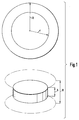
- Figure 1 shows the shape of a conventional dielectric insert for a dielectric resonator.
- the metallic resonator housing consists of a circular cylinder with the inner diameter R and the inner height H. It contains a dielectric insert in the form of a circular cylindrical dielectric ceramic disk with the diameter r and the height h.
- a C-band filter should be implemented with a center frequency of 3.7 GHz and using dual-mode cavity resonators.
- the EH11 ⁇ mode is used as the working mode.
- FIG. 2 shows a dielectric resonator according to the invention, which has a slot structure.
- a mode distance of 39.5% from the next higher mode can be achieved.
- Figure 2 shows only one embodiment for a large mode spacing. Other structures with an even larger mode spacing are possible.
- the dielectric resonator shown in FIG. 2 consists of a circular-cylindrical resonator housing 1, with a disk-like, likewise circular-cylindrical, one-piece dielectric insert 2.
- a disk-like, likewise circular-cylindrical, one-piece dielectric insert 2 Starting from the disk jacket, two mutually opposite, symmetrical slots 3 are arranged, which extend radially towards the center.
- the total of four slots 3 have essentially the same cross section or, as shown, are formed as a truncated pyramid and taper at an angle of 15 ° in the direction of the disk center.
- the center planes of the slots 3 are each perpendicular to the top surfaces of the resonator housing or the top surfaces of the circular cylindrical insert 2.
- the slots 3 are arranged according to the invention so that they intersect the electrical field lines of the TE01 mode.
- the exemplary embodiment according to FIG. 2 has further advantages with regard to the preferred direction of the dual modes, which can be used for the coupling in microwave filter structures (simple cascading of several dielectric resonators according to the invention).
- FIG. 3 shows a further exemplary embodiment of a dielectric insert according to the invention.
- This insert consists of a cylinder 25 in the central region, around which circular segments 21, 22, 23 and 24 are arranged. These segments 21 to 24 are arranged with respect to one another in such a way that two adjacent segments each form the slots 3, which are point-symmetrical and run radially toward the center of the insert, due to the mutual spacing of their segment surfaces.
- the central region - cylinder 25 - of the dielectric insert projects beyond the remaining regions - segments 21 to 24 - with regard to its thickness (cylinder height). Due to this training, higher modes in particular are capable of oscillation.
- the number can be selected by choosing different dielectric constants, for example a high dielectric constant in the central area compared to a low dielectric constant in the outer areas (segments) of the oscillatable modes and the mode distance.
- the dielectric insert i.e. between the resonator housing wall 1 and the dielectric insert 3
- there is filler material with a dielectric constant of, for example, ⁇ 2 to 4.
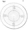
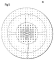
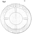
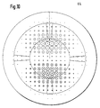
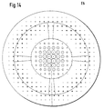
- the associated field line images FIGS. 4 to 15
- FIG. 4 to 15 show, there are 3 in the air-filled or vacuum-filled slots the highest electrical field components.
- the energy density of the modes is concentrated in the dielectric in all cases.
- FIG. 3 there is a six-tuple mode.
- FIG. 16 A further exemplary embodiment of the invention is shown in FIG. 16.
- the dielectric insert 2 consists of a disk-like structure of the same thickness with a rectangular outer boundary.
- the resonator housing 1 is also rectangular.
- the slots 3 each run from the corners of the rectangular structure towards the center of the pane and are point-symmetrical to one another in pairs. Here, too, the slits narrow towards the center of the disk.
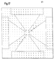
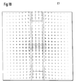
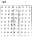
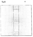
- the electrical fields, designated Ex, and the magnetic fields, designated Bx are shown here in two planes in FIGS. 17 to 24. x takes the values 1 and 2 here (dual mode).
- a spherical structure can also be chosen as a further embodiment of the dielectric insert according to the invention with slots that run from the surface of the sphere towards the center of the sphere.
- the slots 3 When configured as a plate or pill symmetrical in two planes, the slots 3 run almost to the center of the insert and thus prevent the basic mode, which is usually a single mode (depending on the thickness of the plate or pill) and is used for standard filters. At the same time, a dual mode is formed, the energy of which is in the middle of the structure.
- such a structure can also be realized as a composition of standard geometric elements, such as trapezoids and a small cuboid in the middle or triangles and a pill or cuboid in the middle. The same applies to circular cylindrical or spherical structures.
- the slotted structure also offers the possibility to regulate the mode spacing within certain limits with the length and width of the slits.
- a necessary coupling of the two modes (dual mode operation) can also take place in the slots, for example by tuning rods or sawing to different degrees or by grading (FIG. 16).
- the embodiment shown in FIG. 16 offers the following advantages: In order to suppress high field strengths on the one hand (risk of multipacting) and on the other hand to enable more favorable heat conduction (energy dissipation from the dielectric into the resonator housing), a compromise must be striven for while at the same time achieving high quality. Materials with relatively little loss and low dielectric constants are placed like a jaw chuck (cuboid areas 4) between the housing wall and the dielectric and hold the insert or its parts by an external force (spring, screws, etc.).
- the cross-sectional areas of all slots should be smaller overall than the total cross-sectional area of the dielectric material.
- the resonance frequency of the basic mode e.g. in cylindrical standard structures TEO1 mode
- it is advantageous to choose the resonance frequency of the basic mode e.g. in cylindrical standard structures TEO1 mode to be approximately as large as the resonance frequencies of the higher modes.
- the individual segments of the dielectric insert are attached to the inner walls of the housing, it is advantageous to attach these segments to these walls in particular to increase the resonator quality via superconducting bridges, for example HTSL elements.
Landscapes
- Control Of Motors That Do Not Use Commutators (AREA)
Applications Claiming Priority (2)
| Application Number | Priority Date | Filing Date | Title |
|---|---|---|---|
| DE19537477 | 1995-10-09 | ||
| DE19537477A DE19537477A1 (de) | 1995-10-09 | 1995-10-09 | Dielektrischer Resonator sowie Verwendung |
Publications (2)
| Publication Number | Publication Date |
|---|---|
| EP0768725A2 true EP0768725A2 (fr) | 1997-04-16 |
| EP0768725A3 EP0768725A3 (fr) | 1999-10-13 |
Family
ID=7774336
Family Applications (1)
| Application Number | Title | Priority Date | Filing Date |
|---|---|---|---|
| EP96114592A Withdrawn EP0768725A3 (fr) | 1995-10-09 | 1996-09-12 | Résonateur diélectrique et son utilisation |
Country Status (3)
| Country | Link |
|---|---|
| US (1) | US5859574A (fr) |
| EP (1) | EP0768725A3 (fr) |
| DE (1) | DE19537477A1 (fr) |
Cited By (3)
| Publication number | Priority date | Publication date | Assignee | Title |
|---|---|---|---|---|
| EP0920240B1 (fr) * | 1997-11-28 | 2004-08-11 | Matsushita Electric Industrial Co., Ltd. | Alimentation en énergie haute fréquence pour une lampe sans électrodes à haute fréquence |
| CN105006617A (zh) * | 2015-08-19 | 2015-10-28 | 江苏吴通通讯股份有限公司 | 三模介质腔体滤波器 |
| CN110197941A (zh) * | 2018-02-26 | 2019-09-03 | 上海诺基亚贝尔股份有限公司 | 谐振器装置、滤波器和通信设备 |
Families Citing this family (27)
| Publication number | Priority date | Publication date | Assignee | Title |
|---|---|---|---|---|
| US6169467B1 (en) * | 1998-06-18 | 2001-01-02 | El-Badawy Amien El-Sharawy | Dielectric resonator comprising a dielectric resonator disk having a hole |
| JP3444218B2 (ja) * | 1999-02-10 | 2003-09-08 | 株式会社村田製作所 | 誘電体共振器、誘電体フィルタ、誘電体デュプレクサ、発振器、通信機装置 |
| JP3506077B2 (ja) * | 1999-11-24 | 2004-03-15 | 株式会社村田製作所 | 多重モード誘電体共振器装置、フィルタ、デュプレクサおよび通信装置 |
| JP3506076B2 (ja) * | 1999-11-24 | 2004-03-15 | 株式会社村田製作所 | 多重モード誘電体共振器装置、フィルタ、デュプレクサおよび通信装置 |
| US6545571B2 (en) | 2001-09-12 | 2003-04-08 | El-Badawy Amien El-Sharawy | Tunable HEογδ mode dielectric resonator |
| US7042314B2 (en) * | 2001-11-14 | 2006-05-09 | Radio Frequency Systems | Dielectric mono-block triple-mode microwave delay filter |
| US7068127B2 (en) * | 2001-11-14 | 2006-06-27 | Radio Frequency Systems | Tunable triple-mode mono-block filter assembly |
| US7057480B2 (en) * | 2002-09-17 | 2006-06-06 | M/A-Com, Inc. | Cross-coupled dielectric resonator circuit |
| US7310031B2 (en) * | 2002-09-17 | 2007-12-18 | M/A-Com, Inc. | Dielectric resonators and circuits made therefrom |
| US20040257176A1 (en) * | 2003-05-07 | 2004-12-23 | Pance Kristi Dhimiter | Mounting mechanism for high performance dielectric resonator circuits |
| US6954122B2 (en) * | 2003-12-16 | 2005-10-11 | Radio Frequency Systems, Inc. | Hybrid triple-mode ceramic/metallic coaxial filter assembly |
| US20050200437A1 (en) * | 2004-03-12 | 2005-09-15 | M/A-Com, Inc. | Method and mechanism for tuning dielectric resonator circuits |
| US7088203B2 (en) * | 2004-04-27 | 2006-08-08 | M/A-Com, Inc. | Slotted dielectric resonators and circuits with slotted dielectric resonators |
| US7388457B2 (en) | 2005-01-20 | 2008-06-17 | M/A-Com, Inc. | Dielectric resonator with variable diameter through hole and filter with such dielectric resonators |
| US7583164B2 (en) * | 2005-09-27 | 2009-09-01 | Kristi Dhimiter Pance | Dielectric resonators with axial gaps and circuits with such dielectric resonators |
| US7352264B2 (en) * | 2005-10-24 | 2008-04-01 | M/A-Com, Inc. | Electronically tunable dielectric resonator circuits |
| US7705694B2 (en) * | 2006-01-12 | 2010-04-27 | Cobham Defense Electronic Systems Corporation | Rotatable elliptical dielectric resonators and circuits with such dielectric resonators |
| US7719391B2 (en) * | 2006-06-21 | 2010-05-18 | Cobham Defense Electronic Systems Corporation | Dielectric resonator circuits |
| US20080272860A1 (en) * | 2007-05-01 | 2008-11-06 | M/A-Com, Inc. | Tunable Dielectric Resonator Circuit |
| US7456712B1 (en) * | 2007-05-02 | 2008-11-25 | Cobham Defense Electronics Corporation | Cross coupling tuning apparatus for dielectric resonator circuit |
| IT1391339B1 (it) * | 2008-10-03 | 2011-12-05 | Torino Politecnico | Struttura tubolare con diametro interno termicamente stabilizzato,in particolare per un risonatore a microonde |
| EP3200273B1 (fr) * | 2014-09-24 | 2020-08-19 | KYOCERA Corporation | Résonateur, filtre, et dispositif de communication |
| EP3675276B1 (fr) * | 2017-11-14 | 2023-07-26 | Huawei Technologies Co., Ltd. | Résonateur diélectrique et filtre |
| RU2690693C1 (ru) * | 2018-10-05 | 2019-06-05 | Общество с ограниченной ответственностью "Группа компаний "Ботлихский радиозавод"" | Фрактальные взаимосвязанные резонаторы сверхвысокочастотных электромагнитных колебаний в виде диэлектрических трехгранных односторонних поверхностей с металлическими обкладками |
| CN110600841B (zh) * | 2019-10-29 | 2024-06-07 | 苏州瑞玛精密工业股份有限公司 | 介质滤波器的电容耦合结构 |
| IT202200000638A1 (it) * | 2022-01-17 | 2023-07-17 | Commscope Technologies Llc | Risonatori a cavità sospese |
| CN114976561B (zh) * | 2022-04-24 | 2024-05-03 | 摩比天线技术(深圳)有限公司 | 三模介质谐振器及其滤波器 |
Family Cites Families (12)
| Publication number | Priority date | Publication date | Assignee | Title |
|---|---|---|---|---|
| US4423397A (en) * | 1980-06-30 | 1983-12-27 | Murata Manufacturing Co., Ltd. | Dielectric resonator and filter with dielectric resonator |
| SU1058014A1 (ru) * | 1982-10-20 | 1983-11-30 | Киевское Высшее Военное Инженерное Дважды Краснознаменное Училище Связи Им.М.И.Калинина | Диэлектрический резонатор |
| JPS63299604A (ja) * | 1987-05-29 | 1988-12-07 | Murata Mfg Co Ltd | 誘電体共振器装置 |
| CA1251835A (fr) * | 1988-04-05 | 1989-03-28 | Wai-Cheung Tang | Multiplexeur a resonateurs images dielectriques |
| CA2048404C (fr) * | 1991-08-02 | 1993-04-13 | Raafat R. Mansour | Filtres bimodes avec resonateurs dielectriques a ouvertures |
| JP2643677B2 (ja) * | 1991-08-29 | 1997-08-20 | 株式会社村田製作所 | 誘電体共振器装置 |
| US5233319A (en) * | 1992-03-27 | 1993-08-03 | The United States Of America As Represented By The Secretary Of The Army | Low-cost, low-noise, temperature-stable, tunable dielectric resonator oscillator |
| GB2276039A (en) * | 1993-03-12 | 1994-09-14 | Matra Marconi Space Uk Ltd | Support arrangement for a dielectric element within a cavity, for a dieletric resonator filter |
| JPH0758516A (ja) * | 1993-08-16 | 1995-03-03 | Uniden Corp | 縮退型誘電体共振器を用いた帯域通過フイルタ |
| JP3484739B2 (ja) * | 1993-11-30 | 2004-01-06 | 株式会社村田製作所 | 誘電体共振器及び誘電体共振器の共振周波数調整方法 |
| EP0661770B1 (fr) * | 1993-12-28 | 2001-10-04 | Murata Manufacturing Co., Ltd. | Résonateur diélectrique en double mode TM et filtre l'utilisant |
| JPH07212106A (ja) * | 1994-01-13 | 1995-08-11 | Nippon Dengiyou Kosaku Kk | 分波器 |
-
1995
- 1995-10-09 DE DE19537477A patent/DE19537477A1/de not_active Withdrawn
-
1996
- 1996-09-12 EP EP96114592A patent/EP0768725A3/fr not_active Withdrawn
- 1996-10-08 US US08/726,824 patent/US5859574A/en not_active Expired - Fee Related
Cited By (5)
| Publication number | Priority date | Publication date | Assignee | Title |
|---|---|---|---|---|
| EP0920240B1 (fr) * | 1997-11-28 | 2004-08-11 | Matsushita Electric Industrial Co., Ltd. | Alimentation en énergie haute fréquence pour une lampe sans électrodes à haute fréquence |
| CN105006617A (zh) * | 2015-08-19 | 2015-10-28 | 江苏吴通通讯股份有限公司 | 三模介质腔体滤波器 |
| CN105006617B (zh) * | 2015-08-19 | 2018-02-13 | 江苏吴通连接器有限公司 | 三模介质腔体滤波器 |
| CN110197941A (zh) * | 2018-02-26 | 2019-09-03 | 上海诺基亚贝尔股份有限公司 | 谐振器装置、滤波器和通信设备 |
| CN110197941B (zh) * | 2018-02-26 | 2021-07-16 | 上海诺基亚贝尔股份有限公司 | 谐振器装置、滤波器和通信设备 |
Also Published As
| Publication number | Publication date |
|---|---|
| US5859574A (en) | 1999-01-12 |
| DE19537477A1 (de) | 1997-04-10 |
| EP0768725A3 (fr) | 1999-10-13 |
Similar Documents
| Publication | Publication Date | Title |
|---|---|---|
| DE19537477A1 (de) | Dielektrischer Resonator sowie Verwendung | |
| DE2341903C2 (de) | Filter für elektromagnetische Wellen | |
| DE2538614C3 (de) | Dielektrischer Resonator | |
| DE3688375T2 (de) | Dreifachmodus mit dielektrischen resonatoren belastete bandpassfilter. | |
| DE69935562T2 (de) | Kopplungsstruktur für Hohlraumresonatoren | |
| DE3801251A1 (de) | Dielektrischer resonator | |
| DE69816324T2 (de) | Verbundfilter | |
| DE3888456T2 (de) | Dielektrischer Resonator. | |
| DE3442387A1 (de) | Hornstrahler | |
| DE1203842B (de) | Kupplung zwischen zwei Wellenleiterabschnitten | |
| DE1297768B (de) | Wanderfeldverstaerkerroehre | |
| DE68917548T2 (de) | Koaxialer Wellenleiterphasenschieber. | |
| EP0751579B1 (fr) | Filtre hyperfréquence | |
| DE68911333T2 (de) | Filter mit einem dielektrischen Resonator. | |
| DE69418579T2 (de) | Dielektrischer koaxialer Resonator | |
| DE19921926A1 (de) | Dielektrisches Mikrowellenfilter | |
| DE68917373T2 (de) | Magnetisch abstimmbares Bandpassfilter. | |
| DE1115797B (de) | Speisevorrichtung zum UEbertragen von Hochfrequenzenergie mit einstellbarer Polarisation | |
| DE69810927T2 (de) | Temperaturkompensationsstruktur für hohlraumresonator | |
| DE60103406T2 (de) | Mit dielektrikum belasteter hohlraumresonator für hochfrequenzfilter | |
| DE2657649A1 (de) | Filter fuer sehr kurze elektromagnetische wellen | |
| DE3026257C2 (de) | Millimeterwellen-Zirkulator | |
| DE69017829T2 (de) | Breitbandiges Leistungs-Mikrowellenfenster. | |
| DE102013018484B4 (de) | Dielektrisch gefüllter Resonator für 30GHz-Imux-Applikationen | |
| DE2236234C3 (de) | Dielektrisches Fenster für Mikrowellenenergie |
Legal Events
| Date | Code | Title | Description |
|---|---|---|---|
| PUAI | Public reference made under article 153(3) epc to a published international application that has entered the european phase |
Free format text: ORIGINAL CODE: 0009012 |
|
| AK | Designated contracting states |
Kind code of ref document: A2 Designated state(s): DE FR GB IT NL |
|
| PUAL | Search report despatched |
Free format text: ORIGINAL CODE: 0009013 |
|
| AK | Designated contracting states |
Kind code of ref document: A3 Designated state(s): DE FR GB IT NL |
|
| 17P | Request for examination filed |
Effective date: 20000413 |
|
| 17Q | First examination report despatched |
Effective date: 20020318 |
|
| RAP1 | Party data changed (applicant data changed or rights of an application transferred) |
Owner name: TESAT-SPACECOM GMBH & CO. KG |
|
| GRAP | Despatch of communication of intention to grant a patent |
Free format text: ORIGINAL CODE: EPIDOSNIGR1 |
|
| STAA | Information on the status of an ep patent application or granted ep patent |
Free format text: STATUS: THE APPLICATION IS DEEMED TO BE WITHDRAWN |
|
| 18D | Application deemed to be withdrawn |
Effective date: 20040427 |