EP0768733A2 - Connecteur électrique ayant un coulisseau de commande - Google Patents
Connecteur électrique ayant un coulisseau de commande Download PDFInfo
- Publication number
- EP0768733A2 EP0768733A2 EP96115726A EP96115726A EP0768733A2 EP 0768733 A2 EP0768733 A2 EP 0768733A2 EP 96115726 A EP96115726 A EP 96115726A EP 96115726 A EP96115726 A EP 96115726A EP 0768733 A2 EP0768733 A2 EP 0768733A2
- Authority
- EP
- European Patent Office
- Prior art keywords
- connector
- actuating slide
- actuating
- plug
- plugs
- Prior art date
- Legal status (The legal status is an assumption and is not a legal conclusion. Google has not performed a legal analysis and makes no representation as to the accuracy of the status listed.)
- Withdrawn
Links
- 230000000295 complement effect Effects 0.000 claims abstract description 8
- 238000003780 insertion Methods 0.000 description 2
- 230000037431 insertion Effects 0.000 description 2
- 238000011161 development Methods 0.000 description 1
- 230000018109 developmental process Effects 0.000 description 1
Images


Classifications
-
- H—ELECTRICITY
- H01—ELECTRIC ELEMENTS
- H01R—ELECTRICALLY-CONDUCTIVE CONNECTIONS; STRUCTURAL ASSOCIATIONS OF A PLURALITY OF MUTUALLY-INSULATED ELECTRICAL CONNECTING ELEMENTS; COUPLING DEVICES; CURRENT COLLECTORS
- H01R13/00—Details of coupling devices of the kinds covered by groups H01R12/70 or H01R24/00 - H01R33/00
- H01R13/62—Means for facilitating engagement or disengagement of coupling parts or for holding them in engagement
- H01R13/629—Additional means for facilitating engagement or disengagement of coupling parts, e.g. aligning or guiding means, levers, gas pressure electrical locking indicators, manufacturing tolerances
- H01R13/62977—Pivoting levers actuating linearly camming means
-
- H—ELECTRICITY
- H01—ELECTRIC ELEMENTS
- H01R—ELECTRICALLY-CONDUCTIVE CONNECTIONS; STRUCTURAL ASSOCIATIONS OF A PLURALITY OF MUTUALLY-INSULATED ELECTRICAL CONNECTING ELEMENTS; COUPLING DEVICES; CURRENT COLLECTORS
- H01R13/00—Details of coupling devices of the kinds covered by groups H01R12/70 or H01R24/00 - H01R33/00
- H01R13/62—Means for facilitating engagement or disengagement of coupling parts or for holding them in engagement
- H01R13/629—Additional means for facilitating engagement or disengagement of coupling parts, e.g. aligning or guiding means, levers, gas pressure electrical locking indicators, manufacturing tolerances
- H01R13/62905—Additional means for facilitating engagement or disengagement of coupling parts, e.g. aligning or guiding means, levers, gas pressure electrical locking indicators, manufacturing tolerances comprising a camming member
- H01R13/62911—U-shaped sliding element
Definitions
- the invention relates to an electrical connector with an actuating slide which can be connected to a second complementary connector, the actuating slide being inserted into the housing of the first connector and cooperating with a second connector in order to insert the pair of connectors into one another, during the actuation of the actuation slide to connect and disconnect the connector a nose on the second connector is moved through a slot on the operating slide.
- An electrical plug arrangement in particular for door plugs in automobiles, is known from EP 587 174 A2.
- the plug arrangement has an insulating housing, and an actuating slide which is U-shaped. By pressing the Actuating slide, the connector housing is brought into the end position.
- the actuating slide has two slots on each flank of the U.
- the lugs which are arranged on the connector housing, move in these slots.
- the specified electrical connector can be assembled particularly easily. This assembly can not only be done blindly but also with one hand. This is achieved in that the two plugs are already connected to one another in a pre-locking position, even if the actuating slide has not already been actuated to connect the plugs. This makes it possible to secure the two connectors to each other even if they are not yet connected.
- actuating slide has an entry position in which the lugs can be inserted into the guide slots and an end position in which the plugs are connected to one another. If the actuating slide is opened beyond the entry position when the plug is disconnected, the latching arms and the latching hooks are opened with the actuating slide, such that the lugs of the second connector are no longer secured in the first connector.
- a particularly simple actuation of the actuating slide is achieved in that the first plug has a pivotable cover with which the actuating slide can be actuated.
- FIGS. 1a and 1b show two complementary plugs 1, 2.
- the complementary plugs 1, 2 have continuous chambers for receiving electrical contacts.
- the complementary connectors 1,2 have each insulating housing 10.
- the first plug 1 has an actuating slide 3. This actuating slide is moved by means of a pivotable lever 12 perpendicular to the direction of insertion.
- the pivotable lever 12 also serves as a cover for the housing 10 of the electrical connector 1.
- the actuating slide 3 is U-shaped. It has three guide slots 5, 6 and 7 on each side, through which lugs 4, 4 ', 4''are guided on the complementary connector 2 when the connectors are assembled.
- the lugs 4, 4 ', 4'' can be seen in Figure 1b but also in Figure 2b.
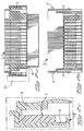
- the enlarged detail shown in FIG. 2c shows the position of the actuating slide 3 in the housing 10.
- a resilient locking arm 8 with a locking lug 9 can be clearly seen.
- the nose 4 latches in a pre-latching position behind the latching hook 9 on the latching arm 8. This can be seen particularly clearly in FIG. 4a.
- the two plugs 1 and 2 are now connected to one another in the pre-locking position, the lugs are located at the beginning of the guide slots in the actuating slide 3. This can be seen particularly clearly from FIG. 3a.
- the nose 4 is also already in the guide slot 6 and is locked behind the locking hook 9 of the locking arm 8.
- the actuating slide 3 has not yet been actuated to join the plugs.
- the actuating slide is shown in its end position in FIGS. 5 and 6.
- the actuating slide 3 is fully inserted and the cover 12 is closed accordingly. If you want to disconnect the plugs from each other again, the pivoting cover 12 is actuated, whereby the actuating slide 3 is moved.
- the lugs 4, 4 ', 4''through the slots 5, 6, 7th moves until the lugs are at the beginning of these slots and the two plugs are back in the pre-locked position.
- the two plugs can also be inserted blindly with only one hand, for example.
Landscapes
- Details Of Connecting Devices For Male And Female Coupling (AREA)
Applications Claiming Priority (2)
| Application Number | Priority Date | Filing Date | Title |
|---|---|---|---|
| DE19537886A DE19537886B4 (de) | 1995-10-11 | 1995-10-11 | Elektrischer Stecker mit einem Betätigungsschieber |
| DE19537886 | 1995-10-11 |
Publications (2)
| Publication Number | Publication Date |
|---|---|
| EP0768733A2 true EP0768733A2 (fr) | 1997-04-16 |
| EP0768733A3 EP0768733A3 (fr) | 1999-02-03 |
Family
ID=7774596
Family Applications (1)
| Application Number | Title | Priority Date | Filing Date |
|---|---|---|---|
| EP96115726A Withdrawn EP0768733A3 (fr) | 1995-10-11 | 1996-10-01 | Connecteur électrique ayant un coulisseau de commande |
Country Status (4)
| Country | Link |
|---|---|
| US (1) | US5785540A (fr) |
| EP (1) | EP0768733A3 (fr) |
| JP (1) | JP3956159B2 (fr) |
| DE (1) | DE19537886B4 (fr) |
Families Citing this family (12)
| Publication number | Priority date | Publication date | Assignee | Title |
|---|---|---|---|---|
| JP3156843B2 (ja) * | 1996-09-30 | 2001-04-16 | 矢崎総業株式会社 | スライド式低挿入力コネクタ |
| JP3467373B2 (ja) * | 1997-03-12 | 2003-11-17 | 矢崎総業株式会社 | コネクタの嵌合構造 |
| JP2000268911A (ja) * | 1999-03-08 | 2000-09-29 | Whitaker Corp:The | 電気コネクタ |
| DE19939408C1 (de) * | 1999-08-20 | 2001-03-29 | Framatome Connectors Int | Elektrischer Steckverbinder |
| US6174190B1 (en) | 1999-10-26 | 2001-01-16 | Keith Frank Tharp | Connector having a slide rail latch release |
| US6254418B1 (en) | 2000-08-16 | 2001-07-03 | The Jpm Company | Latch release |
| US6322386B1 (en) | 2000-09-12 | 2001-11-27 | The Jpm Company | Connector boot with integral latch release |
| JP3899989B2 (ja) * | 2002-04-12 | 2007-03-28 | オムロン株式会社 | 着脱用レバー |
| JP4780994B2 (ja) * | 2005-04-01 | 2011-09-28 | 住友電装株式会社 | レバー式コネクタ |
| JP4494443B2 (ja) * | 2007-08-10 | 2010-06-30 | タイコエレクトロニクスジャパン合同会社 | レバー式コネクタ |
| JP5736940B2 (ja) * | 2011-05-10 | 2015-06-17 | 住友電装株式会社 | レバー式コネクタ |
| DE102014001517B4 (de) * | 2013-02-26 | 2017-02-16 | Sumitomo Wiring Systems, Ltd. | Verbinder und damit versehene Verbinderanordnung |
Family Cites Families (15)
| Publication number | Priority date | Publication date | Assignee | Title |
|---|---|---|---|---|
| US2888662A (en) * | 1954-03-04 | 1959-05-26 | Amp Inc | Electrical connector |
| FR2402949A1 (fr) * | 1977-09-09 | 1979-04-06 | Amp France | Connecteur electrique comportant un contact femelle loge dans un boitier isolant d'une seule piece |
| JPS5911414Y2 (ja) * | 1980-10-01 | 1984-04-07 | 東海電線株式会社 | 電気接続子 |
| US4679887A (en) * | 1982-03-24 | 1987-07-14 | Amp Incorporated | Electrical terminal |
| US4448468A (en) * | 1982-07-09 | 1984-05-15 | Amp Incorporated | Receptacle terminal having latching feature |
| DE3244939C1 (de) * | 1982-12-04 | 1984-03-29 | Kabelwerke Reinshagen Gmbh, 5600 Wuppertal | Verriegelbare elektrische Flachsteckbuchse und damit versehener elektrischer Verbinder |
| US4534613A (en) * | 1983-10-31 | 1985-08-13 | Amp Incorporated | Receptacle terminal having locking lance |
| DE3645179C3 (de) * | 1985-03-04 | 1997-09-04 | Amp Inc | Elektrische Verbinderanordnung mit einem Steuerflächensystem |
| US5322460A (en) * | 1988-12-23 | 1994-06-21 | The Whitaker Corporation | Receptacle terminal having retention means |
| GB9219328D0 (en) * | 1992-09-11 | 1992-10-28 | Amp Gmbh | Automotive door-to-body electrical |
| DE4243268A1 (de) * | 1992-12-19 | 1994-06-23 | Bosch Gmbh Robert | Lösbare Steckverbindung |
| DE69401824T2 (de) * | 1993-01-06 | 1997-06-12 | Sumitomo Wiring Systems | Steckverbinder, der die Betätigung eines Hebels benutzt |
| JP2772309B2 (ja) * | 1993-03-17 | 1998-07-02 | 矢崎総業株式会社 | レバー結合式コネクタ |
| JP2970347B2 (ja) * | 1993-09-28 | 1999-11-02 | 住友電装株式会社 | コネクタ |
| JP3212210B2 (ja) * | 1994-02-25 | 2001-09-25 | タイコエレクトロニクスアンプ株式会社 | カム部材付きコネクタ |
-
1995
- 1995-10-11 DE DE19537886A patent/DE19537886B4/de not_active Expired - Fee Related
-
1996
- 1996-10-01 EP EP96115726A patent/EP0768733A3/fr not_active Withdrawn
- 1996-10-07 US US08/726,730 patent/US5785540A/en not_active Expired - Lifetime
- 1996-10-09 JP JP28748996A patent/JP3956159B2/ja not_active Expired - Fee Related
Also Published As
| Publication number | Publication date |
|---|---|
| DE19537886A1 (de) | 1997-04-17 |
| DE19537886B4 (de) | 2005-07-21 |
| JPH09115605A (ja) | 1997-05-02 |
| JP3956159B2 (ja) | 2007-08-08 |
| EP0768733A3 (fr) | 1999-02-03 |
| US5785540A (en) | 1998-07-28 |
Similar Documents
| Publication | Publication Date | Title |
|---|---|---|
| DE69417634T2 (de) | Elektrischer Verbinder mit verbessertem verschiebbarem Verriegelungsteil | |
| DE69019856T2 (de) | Doppelt verriegelnder Verbinder für einen elektrischen Endkontakt. | |
| EP3518350B1 (fr) | Connecteur électrique enfichable | |
| DE19543009C2 (de) | Verriegelungsmechanismus für ein elektrisches Steckverbinderpaar | |
| DE19614978A1 (de) | Verbinder mit schwenkbarem Kopplungshebel | |
| DE102009053674A1 (de) | Steckverbinder mit Sekundärsteckverbinder | |
| DE19537886B4 (de) | Elektrischer Stecker mit einem Betätigungsschieber | |
| DE19530334B4 (de) | Steckeranordnung mit einem Betätigungsschieber | |
| DE102017107943B3 (de) | Verriegelungsmechanismus zur lösbaren Verriegelung eines ersten Bauteils an einem zweiten Bauteil sowie damit gebildete Anordnung | |
| DE202019101806U1 (de) | Elektrische Steckverbinderanordnung und Halteelement hierzu | |
| DE10005858A1 (de) | Steckverbinder | |
| DE69904100T2 (de) | Elektrische Sicherheits-Steckverbindung in hermaphroditischer bzw. Zwitterausführung | |
| DE69310439T2 (de) | Verriegelbarer elektrischer Verbinderanordnung | |
| EP0846351B1 (fr) | Dispositif constitue de deux demi-fiches pour fixation dans une paroi | |
| DE102020102616A1 (de) | Verriegelungsvorrichtung zum verriegeln eines hebels eines mehrpoligen elektrischen steckverbindergehäuses | |
| EP3403298B1 (fr) | Connecteur enfichable | |
| DE102020106634B3 (de) | Elektrische Steckverbindung und Entriegelungselement | |
| DE10326834B4 (de) | Steckverbinder | |
| DE19828981A1 (de) | Elektrischer Verbinder mit einer Einrichtung zum Gewährleisten der Anschlußposition | |
| DE4410950A1 (de) | Elektrischer Verbinder mit Primär- und Sekundärverriegelung der Kontaktelemente | |
| DE69901287T2 (de) | Elektrischer stecker mit einem betätigungsschieber | |
| DE19530844B4 (de) | Elektrischer Steckverbinder mit Betätigungsschieber | |
| DE102018010384B4 (de) | Elektrische Steckverbindung | |
| DE202019105676U1 (de) | Elektrische Steckverbindung und Verriegelungselement | |
| DE19528074A1 (de) | Elektrische Steckeranordnung |
Legal Events
| Date | Code | Title | Description |
|---|---|---|---|
| PUAI | Public reference made under article 153(3) epc to a published international application that has entered the european phase |
Free format text: ORIGINAL CODE: 0009012 |
|
| AK | Designated contracting states |
Kind code of ref document: A2 Designated state(s): DE FR GB IT |
|
| PUAL | Search report despatched |
Free format text: ORIGINAL CODE: 0009013 |
|
| AK | Designated contracting states |
Kind code of ref document: A3 Designated state(s): DE FR GB IT |
|
| STAA | Information on the status of an ep patent application or granted ep patent |
Free format text: STATUS: THE APPLICATION IS DEEMED TO BE WITHDRAWN |
|
| 18D | Application deemed to be withdrawn |
Effective date: 19990804 |