EP0768960B1 - Dispositif de suspension d'un conducteur electrique a un cable porteur - Google Patents
Dispositif de suspension d'un conducteur electrique a un cable porteur Download PDFInfo
- Publication number
- EP0768960B1 EP0768960B1 EP95925018A EP95925018A EP0768960B1 EP 0768960 B1 EP0768960 B1 EP 0768960B1 EP 95925018 A EP95925018 A EP 95925018A EP 95925018 A EP95925018 A EP 95925018A EP 0768960 B1 EP0768960 B1 EP 0768960B1
- Authority
- EP
- European Patent Office
- Prior art keywords
- cable
- pendulum
- contact wire
- carrying cable
- connection
- Prior art date
- Legal status (The legal status is an assumption and is not a legal conclusion. Google has not performed a legal analysis and makes no representation as to the accuracy of the status listed.)
- Expired - Lifetime
Links
- 239000004020 conductor Substances 0.000 title claims abstract description 10
- 210000000078 claw Anatomy 0.000 claims description 27
- 230000005226 mechanical processes and functions Effects 0.000 description 3
- 230000000712 assembly Effects 0.000 description 2
- 238000000429 assembly Methods 0.000 description 2
- 230000015572 biosynthetic process Effects 0.000 description 2
- 238000009826 distribution Methods 0.000 description 2
- 239000000725 suspension Substances 0.000 description 2
- 238000002788 crimping Methods 0.000 description 1
- 238000004519 manufacturing process Methods 0.000 description 1
- 239000002184 metal Substances 0.000 description 1
- 238000000034 method Methods 0.000 description 1
Images

Classifications
-
- B—PERFORMING OPERATIONS; TRANSPORTING
- B60—VEHICLES IN GENERAL
- B60M—POWER SUPPLY LINES, AND DEVICES ALONG RAILS, FOR ELECTRICALLY- PROPELLED VEHICLES
- B60M1/00—Power supply lines for contact with collector on vehicle
- B60M1/12—Trolley lines; Accessories therefor
- B60M1/20—Arrangements for supporting or suspending trolley wires, e.g. from buildings
- B60M1/225—Arrangements for fixing trolley wires to supporting-lines which are under tension
Definitions
- the present invention relates to a driver suspension device electric to a carrying cable.
- the invention relates more particularly to such a device called connection pendulum for making a connection articulated and electrical mechanics between a conductor such as in particular the wire contact of an overhead electric traction line and its carrying cable.
- connection pendulum supports the contact wire and ensures also the electrical continuity between the carrying cable and this contact wire.
- connection pendulums to achieve such a connection mechanical and electrical.
- DE-A 35 22 543 and DE-A 30 36 045 thus describe connection pendulums ensuring the articulated mechanical and electrical connection between a carrying cable and a conductor, more particularly the contact wire of a line overhead electric traction, in which the pendulum cable ensures continuity between the carrier cable and the contact wire.
- These known systems provide claws to ensure the respective connections to the carrying cable and the wire contact and the connection of the pendulum cable with said claws is carried out by end caps in which the ends of the cable are crimped pendulum.
- FR-A 682 102 describes a contact wire suspension pendulum claw of a line catenary on its carrying cable which consists of two identical parts coming snap onto each other, each part having a groove in which comes to house the contact wire, the assembly being locked by a metal wire passing through the two pieces of the claw.
- the present invention proposes to provide a connection pendulum allowing avoid the formation of electric arcs and eliminate the distribution assemblies electric, the pendulum simultaneously fulfilling an articulated mechanical function contact wire support and a power supply function.
- connection pendulum ensuring the connection articulated and electrical mechanics between a carrying cable and a conductor more particularly the contact wire of an overhead electric traction line
- the pendulum cable provides electrical continuity between the carrying cable and the contact wire
- connection of pendulum cable with connection claws respective to the carrying cable and to the contact wire being produced by end caps in which the ends of the pendulum cable are crimped, called connection claws being produced in two removable parts coming from click on each other to tighten the carrying cable and the wire respectively contact
- the cable is discontinuous: its two ends are respectively crimped onto end pieces integral with lugs engaged in the connection claws and conductors whose ends are respectively crimped in housings integral with said claws and on said lugs ensuring the electrical connection by the pendulum cable between the carrying cable and the wire of contact.
- each of the claws of connection consists of two similar elements coming click on each other, each of said elements comprising a base and a hook element which is provided on its face internal of a profiled flat surface cooperating during latching with the corresponding surface of the element similar hook provided on the second element of the claw, so to form an eye in which the crimped terminal engages on the pendulum cable, the respective lower parts of the two claw elements delimiting a groove in which engages the contact wire or the carrying cable when the snap-fastening of the two elements, thus ensuring the tightening of the wire contact or carrier cable in the corresponding shoe, without have recourse to an independent means of assembly, in particular a tightening by bolts.
- connection pendulum according to the present invention is designed and produced so as to remove the electrical distribution assemblies by filling both the mechanical function and power supply function.
- connection pendulum the connections between the different elements are produced without the need for mounting independent in particular to tightening by bolts.
- the cable (14) of the connection pendulum has ends which are crimped on end caps (32, 32 'respectively), these end caps being integral with a terminal (34, 34 ', respectively) comprising an eye engaging in the connecting claws (18, 18 ').
- cables are provided conductors such as (36, 36 ') whose respective ends are made integral with the terminal (34, 34 'respectively), and of the connection shoe (18, 18 'respectively).
- each conductor cable (36, 36 ') is set in a housing (38, 38 ') integral with the claw connection (18, 18 ') and its other end is held in place by crimping in a housing (40, 40 ') integral respectively a terminal (34, 34 'respectively).
- connection pendulum has the same constitution as that described below with reference to Figures 3 and 4.
- the choice of cable length (14) of the connection pendulum allows the distance between the carrying cable (10) and the contact wire (12), this mode of execution fulfills both the mechanical function of supporting the contact line, and the power supply function, the connections between different elements of the pendulum being obtained without using independent mounting such as in particular tightening by hardware.
- FIGs 3 and 4 represent in details of the elements of an exemplary embodiment of a claw of connection (18, 18 ') which makes the connection between the cable (14) of the pendulum on the one hand, and the carrying cable (10), in what concerns the connection shoe (18), and the contact wire (12) for the connection shoe (18 ').
- each connecting shoe includes two similar elements designed from so as to click on each other as seen on the figure 1.
- Each connection shoe element (18, 18 ') therefore comprises a base (24) and a hook element (26) provided on its internal face of a profiled flat surface (28) intended to come to cooperate with the corresponding surface of the element of similar hook which is provided on the second element of the claw connection (18, 18 '), to form an eye in which just engage the eye of the pods (34 or 34 ') described above, as can be clearly seen in Figures 1 and 2.
- the snap-fastening of the two connecting shoe elements (18, 18 ') when tightening on the corresponding cable, cable carrier (10) or contact wire (12), the latter engaging in the housing delimited by the groove (30) of each of the connection shoe elements.
- the invention allows the manufacture, at serial cost, of connection pendulums in workshop, from pre-established tilting lists, cable lengths (14) of the pendulums being adjusted at the factory, and, moreover, it is adapted to the assembly on site for realizations on demand.
Landscapes
- Engineering & Computer Science (AREA)
- Mechanical Engineering (AREA)
- Connections Effected By Soldering, Adhesion, Or Permanent Deformation (AREA)
- Ladders (AREA)
- Suspension Of Electric Lines Or Cables (AREA)
- Chain Conveyers (AREA)
- Communication Cables (AREA)
- Details Of Connecting Devices For Male And Female Coupling (AREA)
- Electric Cable Installation (AREA)
- Current-Collector Devices For Electrically Propelled Vehicles (AREA)
Description
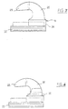
- la figure 1 est une vue en élévation frontale d'un mode de réalisation (mode discontinu) du pendule de connexion selon la présente invention,
- la figure 2 est une vue en élévation latérale de la figure 1.
- les figures 3 et 4 sont respectivement des vues en élévation frontale, de modes de réalisation de l'un des éléments constituant une griffe de raccordement du pendule de connexion selon la présente invention, ces différentes figures étant à des échelles agrandies par rapport aux figures précédentes.
Claims (2)
- Pendule de connexion assurant la liaison mécanique articulée et électrique entre un câble porteur et un conducteur plus particulièrement le fii de contact d'une ligne aérienne de traction électrique, dans lequel le câble du pendule assure la continuité électrique entre le câble porteur et le fil de contact, la connexion du câble (14) du pendule avec les griffes (18, 18') de raccordement respectives au câble porteur (10) et au fil de contact (12) étant réalisée par l'intermédiaire d'embouts (32, 32') dans lesquels sont serties les extrémités du câble du pendule, les dites griffes de raccordement (18, 18') étant réalisées en deux parties amovibles venant s'encliqueter l'une sur l'autre pour serrer respectivement le câble porteur (10) et le fil de contact (12) caractérisé en ce que le câble (14) est discontinu: ses deux extrémités sont respectivement serties sur des embouts (32, 32') solidaires de cosses (34, 34') engagées dans les griffes de raccordement (18, 18') et des conducteurs (36, 36') dont les extrémités sont respectivement serties dans des logements (38, 38') solidaires des dites griffes (18, 18') et sur les dites cosses (34, 34'), assurant la liaison électrique par le câble du pendule (14) entre le câble porteur (10) et le fil de contact (12).
- Pendule de connexion selon la revendication 1 caractérisé en ce que chacune des griffes de raccordement (18, 18') est constituée de deux parties similaires venant s'encliqueter l'une sur l'autre, chacune des dites parties de chaque griffe de raccordement comportant une embase (24) et un élément de crochet (26) qui est pourvu sur sa face interne d'une surface plane profilée (28) venant coopérer lors de l'encliquetage avec la surface correspondante de l'élément de crochet similaire prévu sur la seconde partie de la griffe, afin de constituer un oeil dans lequel vient en prise la cosse (34 , 34') sertie sur le câble (14) du pendule et en ce que les parties inférieures respectives des deux éléments de griffe délimitent une rainure dans laquelle s'engage le fil de contact (12) ou le câble porteur (10) lors de l'encliquetage des deux parties des griffes de raccordement, assurant ainsi le serrage du fil de contact (12) ou du câble porteur (10) dans la griffe correspondante.
Applications Claiming Priority (3)
| Application Number | Priority Date | Filing Date | Title |
|---|---|---|---|
| FR9408422 | 1994-07-07 | ||
| FR9408422A FR2722148B1 (fr) | 1994-07-07 | 1994-07-07 | Dispositif de suspension d'un conducteur electrique a un cable porteur |
| PCT/FR1995/000906 WO1996001747A1 (fr) | 1994-07-07 | 1995-07-06 | Dispositif de suspension d'un conducteur electrique a un cable porteur |
Publications (2)
| Publication Number | Publication Date |
|---|---|
| EP0768960A1 EP0768960A1 (fr) | 1997-04-23 |
| EP0768960B1 true EP0768960B1 (fr) | 2001-01-10 |
Family
ID=9465132
Family Applications (1)
| Application Number | Title | Priority Date | Filing Date |
|---|---|---|---|
| EP95925018A Expired - Lifetime EP0768960B1 (fr) | 1994-07-07 | 1995-07-06 | Dispositif de suspension d'un conducteur electrique a un cable porteur |
Country Status (10)
| Country | Link |
|---|---|
| US (1) | US5730265A (fr) |
| EP (1) | EP0768960B1 (fr) |
| JP (1) | JP3464486B2 (fr) |
| KR (1) | KR970704591A (fr) |
| AT (1) | ATE198570T1 (fr) |
| CA (1) | CA2192698A1 (fr) |
| DE (1) | DE69519859T2 (fr) |
| ES (1) | ES2155133T3 (fr) |
| FR (1) | FR2722148B1 (fr) |
| WO (1) | WO1996001747A1 (fr) |
Families Citing this family (16)
| Publication number | Priority date | Publication date | Assignee | Title |
|---|---|---|---|---|
| GB2330241A (en) * | 1997-05-20 | 1999-04-14 | Whitaker Corp | Dropper assembly for supporting an overhead electrical supply line for trains |
| RU2170680C2 (ru) * | 1998-09-30 | 2001-07-20 | Северо-Кавказская железная дорога МПС России | Узел крепления и регулирования контактного провода |
| AT410197B (de) * | 2000-05-10 | 2003-02-25 | Roehl Hans Heinrich Ing | Hängeklemme |
| RU2238195C2 (ru) * | 2002-10-29 | 2004-10-20 | Закрытое акционерное общество "Универсал-Контактные сети" | Струна для крепления контактного провода к несущему тросу |
| CN103738203B (zh) * | 2014-02-18 | 2015-12-02 | 牛玉田 | 无损压接式整体吊弦及无损压接的方法 |
| FR3026065B1 (fr) * | 2014-09-24 | 2018-07-06 | Tyco Electronics Simel | Pendule de connexion et son dispositif de suspension |
| CN108673136B (zh) * | 2018-07-12 | 2023-11-10 | 中铁电气化(武汉)设计研究院有限公司 | 一种用于整体吊弦预配全自动生产设备的工作台 |
| CN110254297A (zh) * | 2019-07-29 | 2019-09-20 | 中国铁路总公司 | 无螺栓锻造型整体吊弦 |
| WO2021067556A1 (fr) * | 2019-10-01 | 2021-04-08 | Preformed Line Products Co. | Support de fil |
| RU2738225C1 (ru) * | 2019-11-29 | 2020-12-09 | Сергей Михайлович Асташин | Гибкий фиксатор контактных проводов из стального прутка |
| CN110814237A (zh) * | 2019-12-14 | 2020-02-21 | 中铁十一局集团电务工程有限公司 | 一种吊弦加工用拉线装置 |
| CN113263961B (zh) * | 2021-06-03 | 2024-11-26 | 中铁高铁电气装备股份有限公司 | 一种耐疲劳电连接装置 |
| CN113581024A (zh) * | 2021-09-14 | 2021-11-02 | 任兴堂 | 接触线吊弦线夹、承力索吊弦线夹、吊环式无螺栓整体吊弦 |
| US11565609B1 (en) * | 2022-06-21 | 2023-01-31 | Paul F. White | Low-profile catenary hanger |
| FR3140587A1 (fr) * | 2022-10-11 | 2024-04-12 | Tso Catenaires | équipement portatif de griffage et de dégriffage d’une griffe d’un caténaire |
| CN120056815A (zh) * | 2025-02-28 | 2025-05-30 | 中铁建电气化局集团轨道交通器材有限公司 | 一种三角支撑结构的电连接装置 |
Family Cites Families (6)
| Publication number | Priority date | Publication date | Assignee | Title |
|---|---|---|---|---|
| FR682102A (fr) * | 1929-09-20 | 1930-05-23 | Griffe de pendule pour ligne caténaire de traction électrique | |
| DE656602C (de) * | 1936-10-04 | 1938-03-16 | Aeg | Haengerklemme fuer Kettenfahrleitungen elektrischer Bahnen |
| US2304763A (en) * | 1941-05-27 | 1942-12-08 | Ohio Brass Co | Trolley wire support |
| DE3036045A1 (de) * | 1980-09-24 | 1982-05-06 | Siemens AG, 1000 Berlin und 8000 München | Kettenwerk fuer fahrleitungen elektrischer bahnen mit dem fahrdraht zugeordnetem hilfsseil |
| DE3522543A1 (de) * | 1985-06-24 | 1987-01-02 | Siemens Ag | Haenger fuer kettenfahrleitungen elektrischer bahnen |
| US5421068A (en) * | 1993-09-13 | 1995-06-06 | The Whitaker Corporation | Fastener assembly |
-
1994
- 1994-07-07 FR FR9408422A patent/FR2722148B1/fr not_active Expired - Lifetime
-
1995
- 1995-07-06 DE DE69519859T patent/DE69519859T2/de not_active Expired - Lifetime
- 1995-07-06 WO PCT/FR1995/000906 patent/WO1996001747A1/fr not_active Ceased
- 1995-07-06 ES ES95925018T patent/ES2155133T3/es not_active Expired - Lifetime
- 1995-07-06 KR KR1019970700049A patent/KR970704591A/ko not_active Withdrawn
- 1995-07-06 US US08/765,250 patent/US5730265A/en not_active Expired - Fee Related
- 1995-07-06 JP JP50415696A patent/JP3464486B2/ja not_active Expired - Lifetime
- 1995-07-06 EP EP95925018A patent/EP0768960B1/fr not_active Expired - Lifetime
- 1995-07-06 CA CA002192698A patent/CA2192698A1/fr not_active Abandoned
- 1995-07-06 AT AT95925018T patent/ATE198570T1/de active
Also Published As
| Publication number | Publication date |
|---|---|
| DE69519859D1 (de) | 2001-02-15 |
| FR2722148A1 (fr) | 1996-01-12 |
| US5730265A (en) | 1998-03-24 |
| ES2155133T3 (es) | 2001-05-01 |
| FR2722148B1 (fr) | 1996-12-27 |
| JP3464486B2 (ja) | 2003-11-10 |
| DE69519859T2 (de) | 2001-08-02 |
| EP0768960A1 (fr) | 1997-04-23 |
| KR970704591A (ko) | 1997-09-06 |
| JPH10512824A (ja) | 1998-12-08 |
| WO1996001747A1 (fr) | 1996-01-25 |
| CA2192698A1 (fr) | 1996-01-25 |
| ATE198570T1 (de) | 2001-01-15 |
Similar Documents
| Publication | Publication Date | Title |
|---|---|---|
| EP0768960B1 (fr) | Dispositif de suspension d'un conducteur electrique a un cable porteur | |
| FR2601516A2 (fr) | Connecteur de derivation isole pour cables electriques | |
| EP3267231B1 (fr) | Fiche de connexion a une embase de panneau de boitier d'equipement electronique, munie de moyens d'anti-casse de câble optique sur lequel la fiche est montee | |
| EP0286530A1 (fr) | Procédé de réalisation de cosses en plomb ou objets analogues sur des câbles en aluminium | |
| FR2819943A1 (fr) | Connecteur electrique a contacts multiples | |
| FR2635615A1 (fr) | Accessoire de branchement pour cable a relier a un quelconque circuit | |
| FR2899027A1 (fr) | Harnais electrique blinde a connecteur coude et son procede de fabrication | |
| EP0860899B1 (fr) | Connecteur à perforation d'isolant | |
| WO2017029453A1 (fr) | Dispositif de connexion électrique amélioré | |
| EP0121637B1 (fr) | Embout droit de raccordement électrique | |
| FR2706684A1 (fr) | Bornier de raccordement électrique de câbles d'alimentation en énergie électrique. | |
| EP0744088A1 (fr) | Fiche electrique du type fiche anglaise | |
| FR2915630A1 (fr) | Porte-balai avec connexion sertie | |
| FR2675958A1 (fr) | Dispositif de securite pour le branchement et le retrait d'une lampe a incandescence a culots lateraux. | |
| FR2722615A1 (fr) | Contact lyre pour connecteur electrique | |
| EP0227538A1 (fr) | Procédé pour fixer à une plaque de support un conducteur électrique et application du procédé à la réalisation de dispositifs de détection d'usure de garnitures de friction | |
| EP4367763B1 (fr) | Système comprenant un câble et un manchon d'étanchéité pour ce câble | |
| FR2459544A1 (fr) | Perfectionnements aux raccordements entre un ensemble moteur et un socle porte-contacts d'un relais electromagnetique | |
| FR2754952A1 (fr) | Machine electrique tournante avec composant en option | |
| FR3056948B1 (fr) | Bloc de commande electrique pour garniture de portiere | |
| EP0327478A1 (fr) | Embout de raccordement électrique | |
| EP0862801A1 (fr) | Piece de raccordement electrique | |
| FR3026065A1 (fr) | Pendule de connexion et son dispositif de suspension | |
| FR2687509A1 (fr) | Boitier support de prises electriques normalisees et element de precablage incluant un tel boitier. | |
| FR2709025A1 (fr) | Contact électrique élastique. |
Legal Events
| Date | Code | Title | Description |
|---|---|---|---|
| PUAI | Public reference made under article 153(3) epc to a published international application that has entered the european phase |
Free format text: ORIGINAL CODE: 0009012 |
|
| 17P | Request for examination filed |
Effective date: 19970103 |
|
| AK | Designated contracting states |
Kind code of ref document: A1 Designated state(s): AT BE CH DE DK ES FR GB GR IE IT LI LU NL PT SE |
|
| RIN1 | Information on inventor provided before grant (corrected) |
Inventor name: DE FAUCAMBERGE, PHILIPPE Inventor name: THIARD, JEAN-CLAUDE Inventor name: NEIGE, GUY Inventor name: LEMAIRE, ERIC |
|
| 17Q | First examination report despatched |
Effective date: 19970605 |
|
| GRAG | Despatch of communication of intention to grant |
Free format text: ORIGINAL CODE: EPIDOS AGRA |
|
| GRAG | Despatch of communication of intention to grant |
Free format text: ORIGINAL CODE: EPIDOS AGRA |
|
| GRAG | Despatch of communication of intention to grant |
Free format text: ORIGINAL CODE: EPIDOS AGRA |
|
| GRAH | Despatch of communication of intention to grant a patent |
Free format text: ORIGINAL CODE: EPIDOS IGRA |
|
| GRAH | Despatch of communication of intention to grant a patent |
Free format text: ORIGINAL CODE: EPIDOS IGRA |
|
| GRAA | (expected) grant |
Free format text: ORIGINAL CODE: 0009210 |
|
| AK | Designated contracting states |
Kind code of ref document: B1 Designated state(s): AT BE CH DE DK ES FR GB GR IE IT LI LU NL PT SE |
|
| PG25 | Lapsed in a contracting state [announced via postgrant information from national office to epo] |
Ref country code: NL Free format text: LAPSE BECAUSE OF FAILURE TO SUBMIT A TRANSLATION OF THE DESCRIPTION OR TO PAY THE FEE WITHIN THE PRESCRIBED TIME-LIMIT Effective date: 20010110 Ref country code: IE Free format text: LAPSE BECAUSE OF FAILURE TO SUBMIT A TRANSLATION OF THE DESCRIPTION OR TO PAY THE FEE WITHIN THE PRESCRIBED TIME-LIMIT Effective date: 20010110 |
|
| REF | Corresponds to: |
Ref document number: 198570 Country of ref document: AT Date of ref document: 20010115 Kind code of ref document: T |
|
| REG | Reference to a national code |
Ref country code: CH Ref legal event code: EP |
|
| REG | Reference to a national code |
Ref country code: IE Ref legal event code: FG4D Free format text: FRENCH |
|
| REF | Corresponds to: |
Ref document number: 69519859 Country of ref document: DE Date of ref document: 20010215 |
|
| ITF | It: translation for a ep patent filed | ||
| GBT | Gb: translation of ep patent filed (gb section 77(6)(a)/1977) |
Effective date: 20010222 |
|
| PG25 | Lapsed in a contracting state [announced via postgrant information from national office to epo] |
Ref country code: PT Free format text: LAPSE BECAUSE OF FAILURE TO SUBMIT A TRANSLATION OF THE DESCRIPTION OR TO PAY THE FEE WITHIN THE PRESCRIBED TIME-LIMIT Effective date: 20010410 Ref country code: DK Free format text: LAPSE BECAUSE OF FAILURE TO SUBMIT A TRANSLATION OF THE DESCRIPTION OR TO PAY THE FEE WITHIN THE PRESCRIBED TIME-LIMIT Effective date: 20010410 |
|
| PG25 | Lapsed in a contracting state [announced via postgrant information from national office to epo] |
Ref country code: GR Free format text: LAPSE BECAUSE OF FAILURE TO SUBMIT A TRANSLATION OF THE DESCRIPTION OR TO PAY THE FEE WITHIN THE PRESCRIBED TIME-LIMIT Effective date: 20010413 |
|
| REG | Reference to a national code |
Ref country code: ES Ref legal event code: FG2A Ref document number: 2155133 Country of ref document: ES Kind code of ref document: T3 |
|
| NLV1 | Nl: lapsed or annulled due to failure to fulfill the requirements of art. 29p and 29m of the patents act | ||
| PG25 | Lapsed in a contracting state [announced via postgrant information from national office to epo] |
Ref country code: LU Free format text: LAPSE BECAUSE OF NON-PAYMENT OF DUE FEES Effective date: 20010706 |
|
| PG25 | Lapsed in a contracting state [announced via postgrant information from national office to epo] |
Ref country code: BE Free format text: LAPSE BECAUSE OF NON-PAYMENT OF DUE FEES Effective date: 20010731 |
|
| REG | Reference to a national code |
Ref country code: IE Ref legal event code: FD4D |
|
| PLBE | No opposition filed within time limit |
Free format text: ORIGINAL CODE: 0009261 |
|
| STAA | Information on the status of an ep patent application or granted ep patent |
Free format text: STATUS: NO OPPOSITION FILED WITHIN TIME LIMIT |
|
| REG | Reference to a national code |
Ref country code: GB Ref legal event code: IF02 |
|
| 26N | No opposition filed | ||
| BERE | Be: lapsed |
Owner name: SOC. NATIONALE DES CHEMINS DE FER FRANCAIS Effective date: 20010731 Owner name: SIMEL Effective date: 20010731 Owner name: DERMAC INDUSTRIE Effective date: 20010731 |
|
| PGFP | Annual fee paid to national office [announced via postgrant information from national office to epo] |
Ref country code: CH Payment date: 20140728 Year of fee payment: 20 Ref country code: DE Payment date: 20140729 Year of fee payment: 20 |
|
| PGFP | Annual fee paid to national office [announced via postgrant information from national office to epo] |
Ref country code: AT Payment date: 20140619 Year of fee payment: 20 Ref country code: ES Payment date: 20140728 Year of fee payment: 20 Ref country code: GB Payment date: 20140729 Year of fee payment: 20 Ref country code: FR Payment date: 20140717 Year of fee payment: 20 Ref country code: SE Payment date: 20140729 Year of fee payment: 20 |
|
| PGFP | Annual fee paid to national office [announced via postgrant information from national office to epo] |
Ref country code: IT Payment date: 20140724 Year of fee payment: 20 |
|
| REG | Reference to a national code |
Ref country code: DE Ref legal event code: R071 Ref document number: 69519859 Country of ref document: DE |
|
| REG | Reference to a national code |
Ref country code: CH Ref legal event code: PL |
|
| REG | Reference to a national code |
Ref country code: GB Ref legal event code: PE20 Expiry date: 20150705 |
|
| REG | Reference to a national code |
Ref country code: AT Ref legal event code: MK07 Ref document number: 198570 Country of ref document: AT Kind code of ref document: T Effective date: 20150706 |
|
| REG | Reference to a national code |
Ref country code: SE Ref legal event code: EUG |
|
| REG | Reference to a national code |
Ref country code: ES Ref legal event code: FD2A Effective date: 20151026 |
|
| PG25 | Lapsed in a contracting state [announced via postgrant information from national office to epo] |
Ref country code: GB Free format text: LAPSE BECAUSE OF EXPIRATION OF PROTECTION Effective date: 20150705 |
|
| PG25 | Lapsed in a contracting state [announced via postgrant information from national office to epo] |
Ref country code: ES Free format text: LAPSE BECAUSE OF EXPIRATION OF PROTECTION Effective date: 20150707 |