EP0769197B1 - Modul zur verwendung eines miniatur lastschalters - Google Patents
Modul zur verwendung eines miniatur lastschalters Download PDFInfo
- Publication number
- EP0769197B1 EP0769197B1 EP95925078A EP95925078A EP0769197B1 EP 0769197 B1 EP0769197 B1 EP 0769197B1 EP 95925078 A EP95925078 A EP 95925078A EP 95925078 A EP95925078 A EP 95925078A EP 0769197 B1 EP0769197 B1 EP 0769197B1
- Authority
- EP
- European Patent Office
- Prior art keywords
- module
- circuit breaker
- circuit
- mcb
- miniature
- Prior art date
- Legal status (The legal status is an assumption and is not a legal conclusion. Google has not performed a legal analysis and makes no representation as to the accuracy of the status listed.)
- Expired - Lifetime
Links
- 239000004020 conductor Substances 0.000 claims description 27
- 230000007935 neutral effect Effects 0.000 claims description 26
- 230000007246 mechanism Effects 0.000 claims description 17
- 238000004804 winding Methods 0.000 claims description 15
- 238000012544 monitoring process Methods 0.000 claims description 9
- 238000001514 detection method Methods 0.000 claims description 7
- CWYNVVGOOAEACU-UHFFFAOYSA-N Fe2+ Chemical compound [Fe+2] CWYNVVGOOAEACU-UHFFFAOYSA-N 0.000 claims description 2
- 239000002184 metal Substances 0.000 claims description 2
- 229910052751 metal Inorganic materials 0.000 claims description 2
- 238000013411 master cell bank Methods 0.000 description 97
- 230000004044 response Effects 0.000 description 9
- 229920003023 plastic Polymers 0.000 description 6
- 239000004033 plastic Substances 0.000 description 6
- 230000005405 multipole Effects 0.000 description 5
- 230000035945 sensitivity Effects 0.000 description 5
- 230000005291 magnetic effect Effects 0.000 description 3
- 238000003491 array Methods 0.000 description 2
- 230000004907 flux Effects 0.000 description 2
- 238000009434 installation Methods 0.000 description 2
- RYGMFSIKBFXOCR-UHFFFAOYSA-N Copper Chemical compound [Cu] RYGMFSIKBFXOCR-UHFFFAOYSA-N 0.000 description 1
- 230000009471 action Effects 0.000 description 1
- 230000008901 benefit Effects 0.000 description 1
- 229910052802 copper Inorganic materials 0.000 description 1
- 239000010949 copper Substances 0.000 description 1
- 230000000694 effects Effects 0.000 description 1
- 230000005611 electricity Effects 0.000 description 1
- 230000005294 ferromagnetic effect Effects 0.000 description 1
- 238000004519 manufacturing process Methods 0.000 description 1
- 239000003550 marker Substances 0.000 description 1
- 238000012806 monitoring device Methods 0.000 description 1
- 238000000465 moulding Methods 0.000 description 1
- 230000002035 prolonged effect Effects 0.000 description 1
- 239000000779 smoke Substances 0.000 description 1
- 230000000007 visual effect Effects 0.000 description 1
Images


Classifications
-
- H—ELECTRICITY
- H01—ELECTRIC ELEMENTS
- H01H—ELECTRIC SWITCHES; RELAYS; SELECTORS; EMERGENCY PROTECTIVE DEVICES
- H01H71/00—Details of the protective switches or relays covered by groups H01H73/00 - H01H83/00
- H01H71/02—Housings; Casings; Bases; Mountings
- H01H71/0207—Mounting or assembling the different parts of the circuit breaker
- H01H71/0228—Mounting or assembling the different parts of the circuit breaker having provisions for interchangeable or replaceable parts
-
- H—ELECTRICITY
- H01—ELECTRIC ELEMENTS
- H01H—ELECTRIC SWITCHES; RELAYS; SELECTORS; EMERGENCY PROTECTIVE DEVICES
- H01H83/00—Protective switches, e.g. circuit-breaking switches, or protective relays operated by abnormal electrical conditions otherwise than solely by excess current
- H01H83/20—Protective switches, e.g. circuit-breaking switches, or protective relays operated by abnormal electrical conditions otherwise than solely by excess current operated by excess current as well as by some other abnormal electrical condition
-
- H—ELECTRICITY
- H01—ELECTRIC ELEMENTS
- H01H—ELECTRIC SWITCHES; RELAYS; SELECTORS; EMERGENCY PROTECTIVE DEVICES
- H01H71/00—Details of the protective switches or relays covered by groups H01H73/00 - H01H83/00
- H01H71/02—Housings; Casings; Bases; Mountings
- H01H71/0207—Mounting or assembling the different parts of the circuit breaker
- H01H2071/0242—Assembling parts of a circuit breaker by using snap mounting techniques
Definitions
- This invention relates to a module for use with a miniature circuit breaker, as described for example in document DE-A-3 339 400.
- Circuit breakers are electrical switching devices, which may be manually operable, for protecting and controlling the electricity supply to respective electrical circuits in for example a building.
- the term miniature circuit breaker is abbreviated hereinafter as MCB and is herein intended to mean an electrical circuit breaker the dimensions of which satisfy DIN standard 43880, and circuit breakers of a similar shape and size which are designed so as to be interchangeable with circuit breakers satisfying DIN standard 43880.
- circuit breakers of a building are grouped together on a distribution board or in an enclosure which may take the form of a consumer unit housing a mounting arrangement and electrical connectors or bus bars associated with the circuit breakers.
- the grouping of the contact breakers is customarily one or more rectilinear arrays where the contact breakers are positioned side-by-side and thus space lengthways of the array is at a premium.
- the invention is thus advantageous in relation to many forms of contact breaker but may best be appreciated and understood in relation to MCBs.
- MCBs are commonly used in the UK in the electrical consumer units of domestic dwellings and small industrial premises to protect and control the electrical supply to respective electrical circuits of the building.
- Conveniently MCBs have a re-entrant recess in their rear surface arranged to allow them to be fitted onto a mounting rail provided within the consumer unit or the like.
- the end faces of the MCB are provided with terminals arranged to receive bus bars or leads to connect the MCB in the respective electrical circuit.
- MCBs include a manually operable lever often in conjunction with an automatic trip mechanism for operating the contacts of the MCB to break the supply to the respective circuit of the building under particular circumstances.
- the trip mechanisms are arranged to switch off the supply if the current flowing through the MCB to the respective circuit remains above a predetermined level for a prolonged period of time or if there is a sudden increase in the current demand.
- residual current safety devices arranged to monitor the residual current level and/or switch off the supply if the residual current exceeds a predetermined limit
- remote shunt devices arranged to switch off the supply in response to a remote signal
- over- or under-voltage release devices arranged to switch off the supply when the voltage exceeds or falls below a predetermined level.
- a module for use with a miniature circuit breaker of the kind intended to be mounted in side-by-side relationship with other circuit breakers the module being arranged to be mounted upon an end of the housing of the miniature circuit breaker and to perform a monitoring and/or control function associated with the miniature circuit breaker or the circuit controlled thereby in use.
- the module is preferably provided with means arranged to cooperate with the circuit breaker housing to mount the module on said housing in a snap-fit manner.
- the snap-fit mounting is non-releasable.
- the circuit breaker generally will be an active circuit breaker of the type arranged to break the circuit on detection of a current exceeding a predetermined level, but may in some instances be simply a manually operable switch.
- the circuit breaker may comprise a single pole device or a multi-pole device.
- the module is an active device operable to initiate opening of the contacts of the circuit breaker and includes a trip lever which can extend through an opening in an end face of the circuit breaker housing in use to actuate a contact release mechanism of the circuit breaker.
- the module includes an electromechanical actuator for moving said trip lever to actuate said release mechanism in use.
- the module includes means for monitoring residual current or earth leakage.
- the means for monitoring residual current or earth leakage initiates operation of the trip lever on detection of a residual current exceeding a predetermined level.
- the module may include means for adjusting the predetermined level.
- circuit breaker is a multi-pole unit comprising a plurality of single pole circuit breakers ganged to one another in such a manner that tripping of one circuit breaker to open its contacts results in the associated circuit breakers being tripped, it will be recognised that only one of the circuit breakers needs to be provided with an active module.
- the module may, alternatively, comprise a shunt trip unit for tripping the circuit breaker in response to a remote signal; an under voltage release for tripping the circuit breaker on detection of the voltage falling below a predetermined level; or an over-voltage release for tripping the circuit breaker on detection of the voltage exceeding a predetermined level.
- the module may alternatively be a passive device for monitoring and displaying the magnitude of the current flowing through the circuit breaker or the voltage applied thereto.
- the module may include a microprocessor control unit arranged to monitor faults and control the circuit breaker in accordance with the monitored faults or to provide advance warning of impending problems by monitoring changes in the electrical environment.
- the module includes a toroidal sensing winding assembly, and a first conductor extending coaxially through said assembly, said first conductor being hollow so that a second conductor can extend coaxially therethrough such that any current imbalance between the first and second conductors can be sensed by said winding assembly.
- said first conductor is a tubular, non-ferrous metal element extending through the winding assembly and having a terminal attached thereto for connection by a user to a lead, conveniently a neutral lead, of the circuit being monitored, and, in use said second conductor is a further lead, conveniently, a live lead of the circuit, which extends through the first conductor for connection to a terminal of the circuit breaker.
- a further advantage is that the module requires only one terminal to be connected to the circuit being monitored, the lead constituting the second conductor extending through, but not being electrically connected to, the module.
- the residual current module may be passive in that it monitors residual current and provides a warning, or may be active in that it initiates opening of the contacts of the associated circuit breaker.
- the invention further resides in any module as defined in combination with an MCB. Where the module is active it has a trip lever co-operable with the contact release mechanism of the MCB.
- the MCB is a multi-pole unit comprising a plurality of single pole circuit breakers ganged to one another in such a manner that tripping of one circuit breaker to open its contacts results in the associated circuit breakers being tripped, only one of the circuit breakers being provided with an active module.
- the invention still further resides in the combination of three MCBs in side-by-side relationship and ganged to provide a three phase unit, and an active module of width equal to the three ganged MCB unit, mounted on an end of the unit, and housing a trip lever co-operable with the contact release mechanism of one of the MCBs, such that by virtue of the ganging of the MCBs tripping said one will trip all three.
- said module is arranged to monitor earth leakage in all three phases of a three phase supply controlled by the unit.
- the MCB 1 illustrated in Figure 1 is shaped so as to satisfy DIN standard 43880 which specifies the external shape and dimensions of a miniature electrical circuit breaker.
- the MCB 1 includes a recess 2 provided in the rear surface thereof for receiving a mounting rail provided within a domestic consumer unit; a service enclosure; or a distribution board, panel or the like all of which are referred to generically as a "service enclosure".
- One wall of the recess is provided with a tongue or rail clip 3 which is movable between a retracted position in which an end of the tongue 3 is housed substantially within a slot provided in the body of the MCB 1 and an exposed position in which the end of the tongue 3 protrudes into the recess 2 by an amount such that when the MCB 1 is mounted upon a rail, the tongue 3 engages behind the edge of the rail preventing removal of the MCB 1 therefrom.
- the tongue 3 is preferably biased towards its exposed position by a helical spring or by the action of a resilient portion of the tongue 3 engaging with a ramped surface provided within the slot.
- the end faces 4 of the MCB 1 are apertured to provide access to input and output terminals arranged to be connected in the electrical circuit to be controlled.
- the MCB In domestic wiring, it is common for the MCB to control the live line of the respective circuit.
- the live connection to the MCB is made by way of a live bus bar provided within the service enclosure, the bus bar being connected to each of the MCBs housed within the enclosure by way of a respective integral tongue received in the live input terminal in one end face of each MCB.
- the live connection from each MCB to its respective circuit is by way of a lead connected at one end to the output terminal of the MCB at the end face thereof opposite the one receiving the live input.
- the neutral line of the circuit is controlled similarly by a separate MCB ganged to the live MCB but this is unusual in UK domestic wiring systems.
- MCB as used herein is broad enough to embrace a manually operable switching device in which the contacts are opened and closed in response to manual movement of an operating lever 5.
- MCB is used in relation to devices which in addition have a tripping mechanism for opening the contacts as a result of a rapid rise in the current flowing through the contacts, above a predetermined level, and/or as a result of an excessive current flowing in excess of a predetermined time.
- MCBs are arranged to be mounted side-by-side, usually with their adjacent side faces in contact to form one or more rectilinear arrays extending vertically or horizontally. The opposite end faces of the MCBs are thus presented outwardly from the respective array.
- the module 10 illustrated in Figures 1, 2 and 3 is arranged to be mounted upon an end face 4 of the MCB 1.
- the module 10 comprises a two piece plastics housing 11 within which is provided suitable electrical/electronic circuitry to perform the chosen function.
- One end of the module 10 conforms with the shape of the end face 4 of the MCB 1 and includes protrusions 12 arranged to engage with correspondingly shaped regions of the MCB 1 in order to mount the module 10 onto the MCB 1.
- the module 10 may be secured to the MCB 1 by way of screws or bolts, but is preferably secured in position in a snap fit manner, the protrusions 12 being arranged to snap into position with respect to the correspondingly shaped regions of the MCB 1. It is preferable for the snap fit arrangement of the MCB and the module to be such that removal of the module 10 is impossible without damaging the module and/or the MCB, such damage providing an indication that a module has been removed.
- the module 10 comprises a residual current device and is arranged for use in conjunction with an MCB having a tripping mechanism.
- the housing of the MCB is provided with an opening in the end face 4 thereof normally closed by a blanking plug or a knock-out cover, and which, when open, exposes a release lever of the MCB tripping mechanism, movement of which results in the mechanism operating to open the MCB contacts and so breaking the circuit controlled thereby.
- the two piece plastics housing 11 of the module 10 houses a small solenoid 13 arranged so that actuation thereof moves a trip lever 14a by way of a trip pin 14, to a position in which an end of the lever 14a extends through an opening in the module housing 11 aligned with the opening of the MCB housing and pushes the release lever of the MCB to a position in which the contact release mechanism trips.
- the solenoid 13 is mounted upon a circuit board 30 and is electrically connected through suitable circuitry also carried by the circuit board 30 to a residual current detector 15 comprising a suitable toroidal ferromagnetic core 16 having a plurality of toroidal windings 16a provided thereon.
- the ends of the windings are connected to terminals 21 which engage and make electrical connections to the board 30.
- the toroidal winding assembly is mounted within a two piece plastics moulding 22 which snaps together rigidly to support the assembly, and extending coaxially through the core 16 is a tubular copper conductor 17 the ends of which are electrically connected to respective terminals 18, 19.
- One of the terminals 18 comprises a screw operated clamp arranged releasable to receive a lead, the other terminal 19 being permanently soldered to a flying lead 19a which leaves the module through an aperture provided in the housing 11.
- the flying lead 19a will be connected inside the service enclosure to the neutral rail, bus bar or multi-way connector thereof.
- the neutral lead of the wiring of the relevant circuit (sometimes called the contractors neutral lead) will be connected to the terminal 18.
- the power supply to the module is derived from the live output terminal of the associated MCB by way of a spring contact protruding from the module to engage the MCB live output terminal.
- a plastics tube 20 forming a further part of the housing 11 extends coaxially through the tubular conductor 17, preventing contact with the interior of the conductor 17 from outside of the module 10.
- the core 16 and the tubular conductor 17 are positioned so that the tube 20 aligns with the aperture in the end wall of the MCB housing through which the MCB output terminal is exposed.
- the live lead from the circuit being controlled by the MCB (the contractor live lead) is threaded through the plastics tube 20, and hence coaxially through the tubular conductor 17, in use, to reach the MCB output terminal.
- the provision of the tubular conductor 17 which forms part of the neutral line of the circuit, and the live lead, extending coaxially through the core 16 result in a substantially balanced magnetic field being produced when the current passing through the contractors live lead is equal to and opposite that passing through the tubular conductor 17. If the circuit develops a fault resulting in only part of the current returning through the tubular conductor 17, the magnetic field is no longer balanced and a current is produced in the windings of the core 16.
- the circuitry of the module 10 is arranged to monitor the current produced in the windings, and to actuate the solenoid 13 to trip the circuit breaker when the current in the windings exceeds a predetermined level.
- the contractor mounts the module 10 on the "output" end 4 of the MCB and connects the input terminal of the MCB to the live bus bar.
- the contractors live lead carrying the live supply to the load is passed through the plastics tube 20 and is connected to the live "output" terminal of the circuit breaker in the usual manner, the housing 11 of the module having an aperture providing access to the screw clamp of MCB output terminal.
- the contractor then connects the contractors neutral lead from the load to the screw clamp terminal 18 and connects the flying lead 19a to the neutral bus bar or connector block within the consumer unit.
- An earth reference lead 29 is also provided, the earth reference lead 29 being connected to the circuitry within the module 10 and extending from the module for connection to the earth rail in the service enclosure.
- a reference level in the earth reference lead 29 is detected by the circuitry on board 30 and may be used to provide an indication that a loss of neutral; a loss of earth, or a live/neutral reversal, has occurred, with associated tripping of the MCB if desired.
- the MCB/module combination can be used to monitor the earth and live of the circuit, and to trip when faults arise, in a situation where loss of a neutral connection is not significant. In such circumstances the lead 29 acts as a supply lead supplying power to the circuitry of the board 30.
- a switch is provided in the module 10 in order to permit adjustment of the sensitivity of the module in relation to residual current.
- the switch is operated by a lever 23 which is normally obscured by a retractable cover 24 forming part of the housing 11. In use, the switch is moved until the desired predetermined sensitivity level is obtained.
- a wire seal is then attached to the cover 24 and a fixed part of the housing through aligned apertures therein to secure the cover 24 in place over the lever 23 to deter unauthorized adjustment of the switch.
- a window in the housing exposes a marker stipe of the lever 23 to provide a visual indication of the chosen sensitivity setting.
- the module further includes a test trip button 25 arranged to allow the user to simulate a residual current fault situation and so test the module 10 to ensure that it will trip the MCB.
- the test button 25 is arranged to operate a switch in a circuit which results in a current flow in the toroidal windings 16a in excess of the threshold set by the sensitivity adjustment switch and should, if the module and MCB are functioning correctly, result in the actuation of the solenoid 13 and hence in tripping of the circuit breaker.
- the test button 25 is provided in an upwardly extending portion 26 of the module 10 which extends in use adjacent the manual operating lever 5 of the MCB. Such positioning of the test button 25 ensures that the button 25 is accessible at the exposed front face of the combined MCB and module 10 when mounted within a service enclosure.
- a snap-fit bezel is provided around the test button 25 to improve the aesthetic appeal of the combination, the bezel including suitable indicia indicating the magnitude of the residual current which results in tripping of the circuit breaker, alternative bezels being provided to accommodate different sensitivity settings.
- the circuit breaker is a multi-pole circuit breaker of the type comprising, in effect, a plurality of single pole MCBs arranged side-by-side to define the multi-pole unit
- the tripping mechanisms of the circuit breakers to be mechanically interconnected (ganged) by pins extending through openings 28 provided in the side faces of the individual circuit breakers, the connection being such that all of the circuit breakers trip in response to one of the breakers tripping.
- a single module 10 can be engaged with any one of the three ganged MCBs to monitor residual current in relation to the circuit controlled thereby and cause tripping of all three MCBs of the unit in response to a residual current fault in relation to the selected MCB.
- the module 10 can be engaged with either MCB. Where live and neutral are being switched the module must be associated with the MCB controlling the live line as described above.
- the contractors neutral lead is connected to the screw operated terminal 18 of the module 10, and the neutral flying lead 19a of the module 10 is connected to the output terminal of the neutral MCB, the input terminal of the neutral MCB being connected to the neutral rail of the service enclosure.
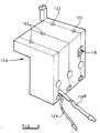
- a single wide module 100 equal in width to the three MCB unit may be attached to an end thereof.
- the module 100 includes one or more residual current detectors electrically linked so that detection of earth leakage in relation to any one or more of the three phases causes actuation of a single solenoid of the module 100 to result in operation of a single trip lever of the module.
- the single trip lever cooperates with one of the three MCBs, the interconnection (ganging) of the three MCBs resulting in the tripping of all three.
- the module 100 has flying neutral lead 119a which extends from the housing of the module 100 adjacent an earth reference lead 129.
- a screw clamp terminal 118 is provided to which the contractors neutral lead, common to the three phases of the supply, is connected, the lead 119a being connected to the supply neutral by way of the neutral rail of the consumer unit housing the MCB unit.
- the terminal 118 is operable by a screwdriver inserted through aperture 121 in the housing wall and three apertures 122 in the same wall provide screwdriver access to the apertures in the MCB housings through which the screw clamps of the respective live output terminals are accessible.
- each of these contractors wires will be introduced through a respective aperture 120 in the wall of the housing of the module 100 to pass along a respective tube, through the earth leakage detector to the live output terminal of its respective MCB.
- the trip mechanism will be operated to trip the chosen one of the ganged MCBs thus tripping all three MCBs and breaking all three live phase connections.
- the modules 10 and 100 may include warning means to provide an indication of the level of the residual current.
- the warning means may comprise a visible indicator for example a flashing light or lights, an analogue or digital meter output, or may comprise an audible warning.
- a visible indicator for example a flashing light or lights, an analogue or digital meter output, or may comprise an audible warning.
- Such a system may be of particular use in applications where a loss of power supply is critical, for example in refrigerated warehouses where a loss in supply may result in the loss of the necessary conditions for safe storage of certain products.
- the warning would provide an indication that a fault has developed and could provide an opportunity for the fault to be corrected before the supply is disconnected.
- a non-critical fault could be indicated by the indicator means whereas a dangerous fault exceeding a predetermined level, for example a fault which may put the operators at risk, would result in immediate tripping to turn off the supply.
- Such a module would include the solenoid tripping means to operate the tripping mechanism of the associated MCB and would include a wire connection or other means such as an infra-red, microwave, radio or ultrasonic receiver to enable operation of the solenoid from a remote position.
- the module may function to monitor the voltage drop across the supplied circuit or circuits and switch off the supply if the voltage exceeds a predetermined level or if the voltage falls below a predetermined level.
- Further functions which could be performed by the single or three phase module are to monitor the current supplied to the circuit or circuits, displaying the supplied current in any suitable manner, or by means of a microprocessor, the circuit or circuits could be controlled in response to the monitoring of the supplied circuit for faults, possibly switching on backup circuits in response to failures detected in the original circuits.
- Such a module could also control the circuit in response to other factors, for example ambient temperature or in response to a smoke detector, so long as a suitable sensor is connected to the module.
- modules 10, 100 are mounted on the end face of the respective MCB then they do not take up space along the mounting rail or the like upon which the MCBs are supported.
- additional functions can be provided without prejudicing the number of MCBs which could otherwise be accommodated in a given application and therefor without prejudicing the number of circuits which can be controlled.
- the module may incorporate alternative forms of electromechanical actuator in place of the solenoid 13, for example a diverted flux relay or a device in which the flux of a permanent magnet is negated when necessary by an electromagnet.
Landscapes
- Breakers (AREA)
- Transmitters (AREA)
- Push-Button Switches (AREA)
- Slide Switches (AREA)
- Distribution Board (AREA)
- Keying Circuit Devices (AREA)
- Emergency Protection Circuit Devices (AREA)
- Coupling Device And Connection With Printed Circuit (AREA)
Claims (10)
- Modul (10) zur Verwendung mit einem Miniaturlastschalter (1) von der mit anderen Lastschaltern nebeneinander anzubringenden Art, wobei der Modul (10) ausgelegt ist, um bei Verwendung eine mit dem Miniaturlastschalter (1) oder dem dadurch gesteuerten Kreis verknüpfte Überwachungs- und/oder Steuerfunktion auszuführen, wobei der Modul dadurch gekennzeichnet ist, daß er ausgelegt ist, um auf einem Ende (4) des Gehäuses eines zuvor zusammengebauten Miniaturlastschalters (1) angebracht zu werden, wobei der Modul über einer Anschlußklemme des Miniaturlastschalters angeordnet ist und einen elektrischen Kontakt umfaßt, der daraus hervorragt, um bei Verwendung in die Anschlußklemme des Miniaturlastschalters (1) einzugreifen, wodurch der Modul seine Stromversorgung von der Anschlußklemme des Miniaturlastschalters abzweigt.
- Modul, wie in Anspruch 1 beansprucht, gekennzeichnet durch Mittel (12), die ausgelegt sind, um mit dem Miniaturlastschaltergehäuse zusammenzuwirken, um den Modul mittels einer nicht freigebbaren Einschnappverbindung auf dem Gehäuse anzubringen.
- Modul, wie in Anspruch 1 oder Anspruch 2 beansprucht, gekennzeichnet durch ein Gebiet (26) des Moduls, das sich bis zu der vorderen Fläche des Lastschalters (1) erstreckt, wobei das Gebiet (26) ein Testauslöseelement (25) trägt, das eine Testfunktion des Moduls auslöst, wenn es während der Verwendung betätigt wird.
- Modul, wie in irgendeinem der Ansprüche 1 bis 3 beansprucht, dadurch gekennzeichnet, daß er ein aktiver Baustein ist, der betätigt werden kann, um die Öffnung der Kontakte des Lastschalters (1) auszulösen, und einen Auslösehebel (14a) umfaßt, der sich bei Verwendung durch eine Öffnung in der Endfläche (4) des Lastschaltergehäuses erstrecken kann, um einen Kontaktfreigabemechanismus des Lastschalters (1) zu betätigen.
- Modul, wie in Anspruch 4 beansprucht, gekennzeichnet durch Mittel, um den Reststrom oder Erdleckstrom zu überwachen, und ausgelegt, um bei Erfassung eines ein vorgegebenes Niveau übersteigenden Reststroms eine Betätigung des Auslösehebels (14a) auszulösen.
- Modul gemäß Anspruch 5, gekennzeichnet durch eine toroidförmige Sensorwicklungseinheit (16, 16a), und einen ersten Leiter (17), der sich koaxial durch die Einheit erstreckt, wobei der erste Leiter (17) hohl ist, so daß ein zweiter Leiter sich koaxial durch ihn hindurch erstrecken kann, wodurch ein eventuelles Stromungleichgewicht zwischen dem ersten und zweiten Leiter von der Wicklungseinheit (16, 16a) wahrgenommen werden kann.
- Modul gemäß Anspruch 6, dadurch gekennzeichnet, daß der erste Leiter (17) ein rohrförmiges, Nichteisenmetallelement ist, das sich durch die Wicklungseinheit (16, 16a) erstreckt, und eine daran befestigte Anschlußklemme (18) hat, zum Anschluß eines Anschlußleiters, in vorteilhafter Weise eines neutralen Anschlußleiters, des zu überwachenden Kreises durch den Verwender, und bei Verwendung der zweite Leiter ein weiterer Anschlußleiter, in vorteilhafter Weise ein heißer Anschlußleiter des Kreises ist, der sich durch den ersten Leiter (17) erstreckt, zum Anschluß an eine Anschlußklemme des Lastschalters.
- Modul gemäß irgendeinem der vorhergehenden Ansprüche, dadurch gekennzeichnet, daß er eine Breite hat, die gleich einem Vielfachen der Lastschalterbreite ist, so daß er mit zwei oder mehr Lastschaltern kombiniert werden kann, die nebeneinander angeordnet sind und zu einer Gruppe zusammengeschlossen sind.
- Modul gemäß irgendeinem der vorhergehenden Ansprüche, in Kombination mit einem Miniaturlastschalter, wobei der Modul auf einem Ende des Gehäuses des Lastschalters angebracht ist und eine mit dem Lastschalter oder dem dadurch gesteuerten Kreis verknüpfte Überwachungs- und/oder Steuerfunktion ausführt.
- Drei Miniaturlastschalter, die nebeneinander angeordnet sind und zu einer Gruppe zusammengeschlossen sind, um eine Dreiphaseneinheit zu bilden, in Kombination mit einem aktiven Modul, wie in irgendeinem der vorhergehenden Ansprüche beansprucht, von gleicher Breite wie die Einheit aus den drei zu einer Gruppe zusammengeschlossenen Miniaturlastschaltern, der auf einem Ende der Einheit angebracht ist, und einen Auslösehebel enthält, der mit dem Kontaktfreigabemechanismus von einem der Miniaturlastschalter so zusammenwirken kann, daß aufgrund des Zusammenschlusses der Miniaturlastschalter zu einer Gruppe beim Auslösen des einen Miniaturlastschalters alle drei Miniaturlastschalter ausgelöst werden.
Applications Claiming Priority (3)
| Application Number | Priority Date | Filing Date | Title |
|---|---|---|---|
| GB9414869A GB9414869D0 (en) | 1994-07-23 | 1994-07-23 | Module for use with a circuit breaker |
| GB9414869 | 1994-07-23 | ||
| PCT/GB1995/001692 WO1996003759A1 (en) | 1994-07-23 | 1995-07-18 | Module for use with a miniature circuit breaker |
Publications (2)
| Publication Number | Publication Date |
|---|---|
| EP0769197A1 EP0769197A1 (de) | 1997-04-23 |
| EP0769197B1 true EP0769197B1 (de) | 1999-04-14 |
Family
ID=10758770
Family Applications (1)
| Application Number | Title | Priority Date | Filing Date |
|---|---|---|---|
| EP95925078A Expired - Lifetime EP0769197B1 (de) | 1994-07-23 | 1995-07-18 | Modul zur verwendung eines miniatur lastschalters |
Country Status (11)
| Country | Link |
|---|---|
| US (1) | US5841616A (de) |
| EP (1) | EP0769197B1 (de) |
| AT (1) | ATE179022T1 (de) |
| DE (1) | DE69509093T2 (de) |
| DK (1) | DK0769197T3 (de) |
| ES (1) | ES2131836T3 (de) |
| GB (1) | GB9414869D0 (de) |
| MY (1) | MY129617A (de) |
| TW (1) | TW417127B (de) |
| WO (1) | WO1996003759A1 (de) |
| ZA (1) | ZA956112B (de) |
Cited By (2)
| Publication number | Priority date | Publication date | Assignee | Title |
|---|---|---|---|---|
| EP3441999A1 (de) * | 2017-08-09 | 2019-02-13 | Schneider Electric USA Inc. | Integrierte lichtbogen- und erdschlussstrommesspaket |
| EP3442000A1 (de) * | 2017-08-09 | 2019-02-13 | Schneider Electric USA, Inc. | Bussing-verfahren mit differentieller strommessung |
Families Citing this family (29)
| Publication number | Priority date | Publication date | Assignee | Title |
|---|---|---|---|---|
| FR2751501B1 (fr) * | 1996-07-16 | 1999-04-30 | Schneider Electric Sa | Appareillage electrique comportant un dispositif de communication |
| US6597266B1 (en) * | 1999-11-05 | 2003-07-22 | Siemens Energy & Automation, Inc. | External actuator interlock mechanism for circuit breaker |
| IT1314086B1 (it) * | 1999-11-23 | 2002-12-04 | Abb Ricerca Spa | Interruttore di potenza di bassa tensione. |
| US6252480B1 (en) * | 2000-02-18 | 2001-06-26 | Siemens Energy & Automation, Inc. | Moving contact and crossbar assembly for a molded case circuit breaker |
| US6670729B2 (en) * | 2001-05-03 | 2003-12-30 | Pluris, Inc. | Intelligent circuit breaker module |
| KR20030058755A (ko) * | 2001-12-31 | 2003-07-07 | 엘지산전 주식회사 | 회로 차단기의 원격 제어장치 |
| FR2834824B1 (fr) | 2002-01-15 | 2004-04-02 | Entrelec | Dispositif de connexion d'un boitier electronique |
| JP4090850B2 (ja) * | 2002-11-13 | 2008-05-28 | 三菱電機株式会社 | 回路遮断器 |
| DE10254038A1 (de) * | 2002-11-20 | 2004-06-03 | Moeller Gmbh | Hilfsauslöser für Motorschutzschalter |
| KR100475072B1 (ko) * | 2002-12-14 | 2005-03-10 | 엘지산전 주식회사 | 모터 보호용 차단기의 부속장치 |
| US6850135B1 (en) * | 2003-08-01 | 2005-02-01 | Gaton Corporation | Circuit breaker trip unit employing a reset overtravel compensating rotary trip lever |
| AT501217B1 (de) * | 2004-07-21 | 2007-09-15 | Moeller Gebaeudeautomation Kg | Schalteinrichtung |
| US7623011B2 (en) * | 2005-10-12 | 2009-11-24 | R. J. Reynolds Tobacco Company | Device for remotely operating a circuit breaker apparatus and associated assembly and method |
| DE102006020702B4 (de) * | 2006-05-04 | 2014-03-13 | Eaton Industries Gmbh | Schutzschalter für Motorschutz und/oder Leitungsschutz |
| EP2064724B1 (de) * | 2006-09-21 | 2014-06-18 | Siemens Aktiengesellschaft | Hilfsauslöser für einen leistungsschalter |
| EP2109129B1 (de) * | 2008-04-11 | 2016-03-30 | ABB Technology AG | Mittelspannungsschutzschalter mit integrierter elektronischer Schutzeinheit |
| AU2009217424B2 (en) * | 2008-09-22 | 2013-08-22 | Jayzi Innovations Pty Ltd | Switch board smoke detector monitoring system |
| US8089282B2 (en) * | 2009-04-18 | 2012-01-03 | General Electric Company | Test assembly for a circuit breaker |
| WO2011041843A1 (en) * | 2009-10-08 | 2011-04-14 | Stephen James Woolley | 3 phase rcbo |
| US8576547B2 (en) | 2011-04-08 | 2013-11-05 | Jayzi Innovation Pty Limited | Electrical switch board smoke detector unit |
| US8749329B2 (en) * | 2011-04-14 | 2014-06-10 | Carling Technologies, Inc. | Magnetic circuit interrupter with current limiting capability |
| DE102011089211A1 (de) * | 2011-12-20 | 2013-01-31 | Siemens Aktiengesellschaft | Schalter, insbesondere Leistungsschalter für Niederspannungen |
| US20140211345A1 (en) | 2013-01-30 | 2014-07-31 | Eaton Corporation | Annunciating or power vending circuit breaker for an electric load |
| WO2015055233A1 (en) | 2013-10-15 | 2015-04-23 | Abb Technology Ltd | Monitoring device and surge arrester system |
| TWI638378B (zh) * | 2016-10-12 | 2018-10-11 | 陳錫瑜 | 開關接點狀態檢示裝置 |
| DE102018202793A1 (de) | 2018-02-23 | 2019-08-29 | Ellenberger & Poensgen Gmbh | Schutzschaltergehäuse |
| KR102500201B1 (ko) * | 2018-05-15 | 2023-02-16 | 미쓰비시덴키 가부시키가이샤 | 회로 차단기 |
| DE102019006330A1 (de) * | 2019-09-09 | 2021-03-11 | OMS Prüfservice GmbH | Elektrische Reihenklemme |
| CN111312562A (zh) * | 2020-03-20 | 2020-06-19 | 沃孚智能科技浙江有限公司 | 一种微型断路器操作面侧嵌式信号装置 |
Family Cites Families (11)
| Publication number | Priority date | Publication date | Assignee | Title |
|---|---|---|---|---|
| GB719219A (en) * | 1951-04-14 | 1954-12-01 | Anderson Boyes & Co Ltd | Improvements in or relating to polyphase current transformers for use in earth leakage protective systems |
| CH499197A (de) * | 1968-03-09 | 1970-11-15 | Stotz Kontakt Gmbh | Schaltschütz mit Kurzschlussauslöser |
| US3812400A (en) * | 1973-03-05 | 1974-05-21 | Ite Imperial Corp | Modular ground fault interrupter |
| DE3140866A1 (de) * | 1981-10-14 | 1983-04-21 | Siemens AG, 1000 Berlin und 8000 München | Anordnung zur vermeidung von fehlimpulsen eines summenstromwandlers |
| JPS6068524A (ja) * | 1983-09-21 | 1985-04-19 | 三菱電機株式会社 | 回路しや断器 |
| DE3339400A1 (de) * | 1983-10-29 | 1985-05-09 | Sursum Elektrizitätsgesellschaft Leyhausen GmbH & Co, 8500 Nürnberg | Selbstschalter mit schlaganker-ausloeser |
| US4686600A (en) * | 1985-04-22 | 1987-08-11 | General Electric Company | Modular ground fault circuit breaker |
| DE9105489U1 (de) * | 1991-05-03 | 1992-09-03 | Klöckner-Moeller GmbH, 5300 Bonn | Leistungsschalter für Energieverteilungsanlagen |
| DE4215900C1 (de) * | 1992-05-14 | 1993-12-23 | Siemens Ag | Anordnung zum Erfassen von Differenzströmen |
| FR2696042B1 (fr) * | 1992-09-24 | 1994-12-09 | Telemecanique | Appareil sectionneur associable à un disjoncteur. |
| US5657193A (en) * | 1996-01-26 | 1997-08-12 | General Electric Company | Electronic control module for motor controller units |
-
1994
- 1994-07-23 GB GB9414869A patent/GB9414869D0/en active Pending
-
1995
- 1995-07-18 ES ES95925078T patent/ES2131836T3/es not_active Expired - Lifetime
- 1995-07-18 DK DK95925078T patent/DK0769197T3/da active
- 1995-07-18 US US08/776,173 patent/US5841616A/en not_active Expired - Lifetime
- 1995-07-18 AT AT95925078T patent/ATE179022T1/de not_active IP Right Cessation
- 1995-07-18 EP EP95925078A patent/EP0769197B1/de not_active Expired - Lifetime
- 1995-07-18 DE DE69509093T patent/DE69509093T2/de not_active Expired - Fee Related
- 1995-07-18 WO PCT/GB1995/001692 patent/WO1996003759A1/en not_active Ceased
- 1995-07-21 MY MYPI95002100A patent/MY129617A/en unknown
- 1995-07-21 ZA ZA956112A patent/ZA956112B/xx unknown
- 1995-07-22 TW TW084107613A patent/TW417127B/zh not_active IP Right Cessation
Cited By (5)
| Publication number | Priority date | Publication date | Assignee | Title |
|---|---|---|---|---|
| EP3441999A1 (de) * | 2017-08-09 | 2019-02-13 | Schneider Electric USA Inc. | Integrierte lichtbogen- und erdschlussstrommesspaket |
| EP3442000A1 (de) * | 2017-08-09 | 2019-02-13 | Schneider Electric USA, Inc. | Bussing-verfahren mit differentieller strommessung |
| US11385300B2 (en) | 2017-08-09 | 2022-07-12 | Schneider Electric USA, Inc. | Differential current sensing bussing method |
| AU2018211266B2 (en) * | 2017-08-09 | 2023-05-25 | Schneider Electric USA, Inc. | Differential Current Sensing Bussing Method |
| AU2023202802B2 (en) * | 2017-08-09 | 2025-02-27 | Schneider Electric USA, Inc. | Differential current sensing bussing method |
Also Published As
| Publication number | Publication date |
|---|---|
| EP0769197A1 (de) | 1997-04-23 |
| TW417127B (en) | 2001-01-01 |
| GB9414869D0 (en) | 1994-09-14 |
| ATE179022T1 (de) | 1999-04-15 |
| DE69509093T2 (de) | 1999-10-28 |
| AU701059B2 (en) | 1999-01-21 |
| AU2934395A (en) | 1996-02-22 |
| US5841616A (en) | 1998-11-24 |
| ES2131836T3 (es) | 1999-08-01 |
| DK0769197T3 (da) | 1999-10-25 |
| DE69509093D1 (de) | 1999-05-20 |
| WO1996003759A1 (en) | 1996-02-08 |
| MY129617A (en) | 2007-04-30 |
| ZA956112B (en) | 1996-03-06 |
Similar Documents
| Publication | Publication Date | Title |
|---|---|---|
| EP0769197B1 (de) | Modul zur verwendung eines miniatur lastschalters | |
| US5572396A (en) | Electric service safety disconnect apparatus with overvoltage and overcurrent protection | |
| US6788508B2 (en) | Compact low AMP electronic circuit breaker or residential load center | |
| US4926282A (en) | Electric circuit breaking apparatus | |
| US10320177B2 (en) | Power distribution system and method, and circuit breaker for use therein | |
| EP0491933B1 (de) | Steckbarer schutzschalter | |
| US6084758A (en) | Power distribution system with circuit breakers remotely resettable by signals transmitted over the power lines | |
| CA2007597C (en) | Molded case circuit breaker auxiliary switch unit | |
| KR101522272B1 (ko) | 회로 차단기의 중성 극 변류기 모듈 및 중성 극 전류 검출 장치 | |
| EP3078090B1 (de) | Verfahren und vorrichtung zur erfassung des zustandes eines schutzschalters | |
| US9111707B2 (en) | Installation switching device with a current sensing unit | |
| US9460879B2 (en) | Circuit breaker assembly including a plurality of controllable circuit breakers for local and/or remote control | |
| CA2949628C (en) | Retrofit cafi/gfi remote control module | |
| KR101834813B1 (ko) | 배선용 차단기 | |
| CN211629005U (zh) | 一种集成在断路器中的电路故障检测模块 | |
| AU701059C (en) | Module for use with a miniature circuit breaker | |
| US4675598A (en) | Current measuring device in an electrical distribution switchboard or enclosure | |
| AU2019204959B2 (en) | Residual current circuit breaker and method of testing same | |
| KR840001584B1 (ko) | 휴대용 비상 안전장치 | |
| EP1724803B1 (de) | Zu einer elektrischen Schaltvorrichtung zuordenbare elektronische Einrichtung | |
| US6388217B1 (en) | Electric power switch with stain relief for attachment wiring | |
| US5136454A (en) | Arrangement for providing ground fault protection | |
| JP7672106B2 (ja) | サージ保護システム、サージ保護装置、ベース装置、及び分電盤 | |
| US11538649B2 (en) | Circuit breaker housing | |
| JP2592004B2 (ja) | 回路遮断器の過電流引外し装置 |
Legal Events
| Date | Code | Title | Description |
|---|---|---|---|
| PUAI | Public reference made under article 153(3) epc to a published international application that has entered the european phase |
Free format text: ORIGINAL CODE: 0009012 |
|
| 17P | Request for examination filed |
Effective date: 19970220 |
|
| AK | Designated contracting states |
Kind code of ref document: A1 Designated state(s): AT BE CH DE DK ES FR GB IE IT LI NL PT SE |
|
| 17Q | First examination report despatched |
Effective date: 19970729 |
|
| GRAG | Despatch of communication of intention to grant |
Free format text: ORIGINAL CODE: EPIDOS AGRA |
|
| GRAG | Despatch of communication of intention to grant |
Free format text: ORIGINAL CODE: EPIDOS AGRA |
|
| GRAG | Despatch of communication of intention to grant |
Free format text: ORIGINAL CODE: EPIDOS AGRA |
|
| GRAH | Despatch of communication of intention to grant a patent |
Free format text: ORIGINAL CODE: EPIDOS IGRA |
|
| GRAH | Despatch of communication of intention to grant a patent |
Free format text: ORIGINAL CODE: EPIDOS IGRA |
|
| GRAA | (expected) grant |
Free format text: ORIGINAL CODE: 0009210 |
|
| AK | Designated contracting states |
Kind code of ref document: B1 Designated state(s): AT BE CH DE DK ES FR GB IE IT LI NL PT SE |
|
| REF | Corresponds to: |
Ref document number: 179022 Country of ref document: AT Date of ref document: 19990415 Kind code of ref document: T |
|
| REG | Reference to a national code |
Ref country code: CH Ref legal event code: EP |
|
| REG | Reference to a national code |
Ref country code: IE Ref legal event code: FG4D |
|
| REG | Reference to a national code |
Ref country code: CH Ref legal event code: NV Representative=s name: RITSCHER & SEIFERT |
|
| ITF | It: translation for a ep patent filed | ||
| REF | Corresponds to: |
Ref document number: 69509093 Country of ref document: DE Date of ref document: 19990520 |
|
| ET | Fr: translation filed | ||
| REG | Reference to a national code |
Ref country code: ES Ref legal event code: FG2A Ref document number: 2131836 Country of ref document: ES Kind code of ref document: T3 |
|
| REG | Reference to a national code |
Ref country code: DK Ref legal event code: T3 |
|
| PLBE | No opposition filed within time limit |
Free format text: ORIGINAL CODE: 0009261 |
|
| STAA | Information on the status of an ep patent application or granted ep patent |
Free format text: STATUS: NO OPPOSITION FILED WITHIN TIME LIMIT |
|
| 26N | No opposition filed | ||
| BERE | Be: lapsed |
Owner name: DELTA CIRCUIT PROTECTION & CONTROLS LTD Effective date: 20010731 |
|
| PG25 | Lapsed in a contracting state [announced via postgrant information from national office to epo] |
Ref country code: NL Free format text: LAPSE BECAUSE OF NON-PAYMENT OF DUE FEES Effective date: 20020201 |
|
| EUG | Se: european patent has lapsed |
Ref document number: 95925078.8 |
|
| GBPC | Gb: european patent ceased through non-payment of renewal fee |
Effective date: 20010718 |
|
| REG | Reference to a national code |
Ref country code: CH Ref legal event code: PL |
|
| REG | Reference to a national code |
Ref country code: DK Ref legal event code: EBP |
|
| NLV4 | Nl: lapsed or anulled due to non-payment of the annual fee |
Effective date: 20020201 |
|
| REG | Reference to a national code |
Ref country code: CH Ref legal event code: AEN Free format text: LE BREVET A ETE REACTIVE SELON LA DEMANDE DE POURSUITE DE LA PROCEDURE DU 15.03.2002. |
|
| REG | Reference to a national code |
Ref country code: IE Ref legal event code: MM4A |
|
| REG | Reference to a national code |
Ref country code: GB Ref legal event code: 728V |
|
| REG | Reference to a national code |
Ref country code: PT Ref legal event code: NF4A Free format text: 'RESTITUTIO IN INTEGRUM' Effective date: 20020405 |
|
| NLXE | Nl: other communications concerning ep-patents (part 3 heading xe) |
Free format text: A REQUEST FOR RESTORATION TO THE PRIOR STATE (ART. 23 OF THE PATENTS ACT 1995) HAS BEEN FILED ON 01.05.02. |
|
| REG | Reference to a national code |
Ref country code: IE Ref legal event code: NE4A |
|
| PG25 | Lapsed in a contracting state [announced via postgrant information from national office to epo] |
Ref country code: SE Free format text: LAPSE BECAUSE OF NON-PAYMENT OF DUE FEES Effective date: 20021024 |
|
| REG | Reference to a national code |
Ref country code: DK Ref legal event code: EBP |
|
| NLXE | Nl: other communications concerning ep-patents (part 3 heading xe) |
Free format text: A REQUEST FOR RESTORATION TO THE PRIOR STATE AS PROVIDED FOR IN ARTICLE 23 OF THE PATENTS ACT 1995 (SEE PUBLICATION IN HEADING XE OF THE PATENT BULLETIN OF 20020701/07) HAS BEEN GRANTED; THE RESTORATION OF THE PATENT HAS BEEN ENTERED IN THE PATENT REGISTER. |
|
| REG | Reference to a national code |
Ref country code: GB Ref legal event code: 728Y |
|
| PGFP | Annual fee paid to national office [announced via postgrant information from national office to epo] |
Ref country code: IE Payment date: 20040714 Year of fee payment: 10 |
|
| PGFP | Annual fee paid to national office [announced via postgrant information from national office to epo] |
Ref country code: CH Payment date: 20040715 Year of fee payment: 10 |
|
| PGFP | Annual fee paid to national office [announced via postgrant information from national office to epo] |
Ref country code: PT Payment date: 20050629 Year of fee payment: 11 |
|
| PG25 | Lapsed in a contracting state [announced via postgrant information from national office to epo] |
Ref country code: IE Free format text: LAPSE BECAUSE OF NON-PAYMENT OF DUE FEES Effective date: 20050718 |
|
| PG25 | Lapsed in a contracting state [announced via postgrant information from national office to epo] |
Ref country code: LI Free format text: LAPSE BECAUSE OF NON-PAYMENT OF DUE FEES Effective date: 20050731 Ref country code: CH Free format text: LAPSE BECAUSE OF NON-PAYMENT OF DUE FEES Effective date: 20050731 |
|
| PGFP | Annual fee paid to national office [announced via postgrant information from national office to epo] |
Ref country code: BE Payment date: 20050916 Year of fee payment: 11 |
|
| REG | Reference to a national code |
Ref country code: CH Ref legal event code: PL |
|
| REG | Reference to a national code |
Ref country code: IE Ref legal event code: MM4A |
|
| PG25 | Lapsed in a contracting state [announced via postgrant information from national office to epo] |
Ref country code: BE Free format text: LAPSE BECAUSE OF NON-PAYMENT OF DUE FEES Effective date: 20060731 |
|
| PG25 | Lapsed in a contracting state [announced via postgrant information from national office to epo] |
Ref country code: PT Free format text: LAPSE BECAUSE OF NON-PAYMENT OF DUE FEES Effective date: 20070118 |
|
| REG | Reference to a national code |
Ref country code: PT Ref legal event code: MM4A Free format text: LAPSE DUE TO NON-PAYMENT OF FEES Effective date: 20070118 |
|
| REG | Reference to a national code |
Ref country code: FR Ref legal event code: TP Ref country code: FR Ref legal event code: CD |
|
| REG | Reference to a national code |
Ref country code: GB Ref legal event code: 732E |
|
| BERE | Be: lapsed |
Owner name: *DELTA CIRCUIT PROTECTION & CONTROLS LTD Effective date: 20060731 |
|
| PGFP | Annual fee paid to national office [announced via postgrant information from national office to epo] |
Ref country code: SE Payment date: 20060706 Year of fee payment: 12 |
|
| PGFP | Annual fee paid to national office [announced via postgrant information from national office to epo] |
Ref country code: DK Payment date: 20080617 Year of fee payment: 14 |
|
| PGFP | Annual fee paid to national office [announced via postgrant information from national office to epo] |
Ref country code: ES Payment date: 20080715 Year of fee payment: 14 Ref country code: DE Payment date: 20080731 Year of fee payment: 14 |
|
| PGFP | Annual fee paid to national office [announced via postgrant information from national office to epo] |
Ref country code: IT Payment date: 20080717 Year of fee payment: 14 Ref country code: FR Payment date: 20080707 Year of fee payment: 14 Ref country code: NL Payment date: 20080619 Year of fee payment: 14 Ref country code: AT Payment date: 20080616 Year of fee payment: 14 |
|
| REG | Reference to a national code |
Ref country code: ES Ref legal event code: PC2A |
|
| REG | Reference to a national code |
Ref country code: DK Ref legal event code: EBP |
|
| NLV4 | Nl: lapsed or anulled due to non-payment of the annual fee |
Effective date: 20100201 |
|
| REG | Reference to a national code |
Ref country code: FR Ref legal event code: ST Effective date: 20100331 |
|
| PG25 | Lapsed in a contracting state [announced via postgrant information from national office to epo] |
Ref country code: FR Free format text: LAPSE BECAUSE OF NON-PAYMENT OF DUE FEES Effective date: 20090731 |
|
| PG25 | Lapsed in a contracting state [announced via postgrant information from national office to epo] |
Ref country code: DE Free format text: LAPSE BECAUSE OF NON-PAYMENT OF DUE FEES Effective date: 20100202 Ref country code: AT Free format text: LAPSE BECAUSE OF NON-PAYMENT OF DUE FEES Effective date: 20090718 |
|
| PG25 | Lapsed in a contracting state [announced via postgrant information from national office to epo] |
Ref country code: DK Free format text: LAPSE BECAUSE OF NON-PAYMENT OF DUE FEES Effective date: 20090731 |
|
| REG | Reference to a national code |
Ref country code: ES Ref legal event code: FD2A Effective date: 20090720 |
|
| PG25 | Lapsed in a contracting state [announced via postgrant information from national office to epo] |
Ref country code: ES Free format text: LAPSE BECAUSE OF NON-PAYMENT OF DUE FEES Effective date: 20090720 |
|
| PG25 | Lapsed in a contracting state [announced via postgrant information from national office to epo] |
Ref country code: IT Free format text: LAPSE BECAUSE OF NON-PAYMENT OF DUE FEES Effective date: 20090718 |
|
| PGFP | Annual fee paid to national office [announced via postgrant information from national office to epo] |
Ref country code: GB Payment date: 20140624 Year of fee payment: 20 |
|
| REG | Reference to a national code |
Ref country code: GB Ref legal event code: PE20 Expiry date: 20150717 |
|
| PG25 | Lapsed in a contracting state [announced via postgrant information from national office to epo] |
Ref country code: GB Free format text: LAPSE BECAUSE OF EXPIRATION OF PROTECTION Effective date: 20150717 |