EP0769353B1 - Dispositif de serrage à grenouillère - Google Patents
Dispositif de serrage à grenouillère Download PDFInfo
- Publication number
- EP0769353B1 EP0769353B1 EP96107559A EP96107559A EP0769353B1 EP 0769353 B1 EP0769353 B1 EP 0769353B1 EP 96107559 A EP96107559 A EP 96107559A EP 96107559 A EP96107559 A EP 96107559A EP 0769353 B1 EP0769353 B1 EP 0769353B1
- Authority
- EP
- European Patent Office
- Prior art keywords
- piston rod
- clamp according
- lever
- toggle clamp
- toggle
- Prior art date
- Legal status (The legal status is an assumption and is not a legal conclusion. Google has not performed a legal analysis and makes no representation as to the accuracy of the status listed.)
- Expired - Lifetime
Links
- 239000000428 dust Substances 0.000 claims description 6
- 238000003466 welding Methods 0.000 claims description 6
- 238000006073 displacement reaction Methods 0.000 claims description 5
- 230000001939 inductive effect Effects 0.000 claims description 3
- 239000000463 material Substances 0.000 claims description 3
- 238000007789 sealing Methods 0.000 claims description 2
- 238000005096 rolling process Methods 0.000 claims 1
- 238000010276 construction Methods 0.000 description 4
- 238000005553 drilling Methods 0.000 description 4
- 238000009423 ventilation Methods 0.000 description 3
- 238000013022 venting Methods 0.000 description 3
- 229910000831 Steel Inorganic materials 0.000 description 2
- 239000011324 bead Substances 0.000 description 2
- 230000000903 blocking effect Effects 0.000 description 2
- 230000008878 coupling Effects 0.000 description 2
- 238000010168 coupling process Methods 0.000 description 2
- 238000005859 coupling reaction Methods 0.000 description 2
- 238000009434 installation Methods 0.000 description 2
- 238000012544 monitoring process Methods 0.000 description 2
- 239000010959 steel Substances 0.000 description 2
- XLYOFNOQVPJJNP-UHFFFAOYSA-N water Substances O XLYOFNOQVPJJNP-UHFFFAOYSA-N 0.000 description 2
- 208000027418 Wounds and injury Diseases 0.000 description 1
- 229910052782 aluminium Inorganic materials 0.000 description 1
- XAGFODPZIPBFFR-UHFFFAOYSA-N aluminium Chemical compound [Al] XAGFODPZIPBFFR-UHFFFAOYSA-N 0.000 description 1
- 238000010009 beating Methods 0.000 description 1
- 230000005540 biological transmission Effects 0.000 description 1
- 230000015572 biosynthetic process Effects 0.000 description 1
- 239000000969 carrier Substances 0.000 description 1
- 230000000295 complement effect Effects 0.000 description 1
- 230000006378 damage Effects 0.000 description 1
- 238000005538 encapsulation Methods 0.000 description 1
- 238000002347 injection Methods 0.000 description 1
- 239000007924 injection Substances 0.000 description 1
- 238000001746 injection moulding Methods 0.000 description 1
- 208000014674 injury Diseases 0.000 description 1
- 230000009191 jumping Effects 0.000 description 1
- 210000003127 knee Anatomy 0.000 description 1
- 210000000629 knee joint Anatomy 0.000 description 1
- 239000007788 liquid Substances 0.000 description 1
- 229910052751 metal Inorganic materials 0.000 description 1
- 239000002184 metal Substances 0.000 description 1
- 239000007769 metal material Substances 0.000 description 1
- 239000012778 molding material Substances 0.000 description 1
- 230000000149 penetrating effect Effects 0.000 description 1
- 230000036316 preload Effects 0.000 description 1
- 239000007921 spray Substances 0.000 description 1
- 230000008719 thickening Effects 0.000 description 1
Images
Classifications
-
- B—PERFORMING OPERATIONS; TRANSPORTING
- B25—HAND TOOLS; PORTABLE POWER-DRIVEN TOOLS; MANIPULATORS
- B25B—TOOLS OR BENCH DEVICES NOT OTHERWISE PROVIDED FOR, FOR FASTENING, CONNECTING, DISENGAGING OR HOLDING
- B25B5/00—Clamps
- B25B5/16—Details, e.g. jaws, jaw attachments
-
- B—PERFORMING OPERATIONS; TRANSPORTING
- B25—HAND TOOLS; PORTABLE POWER-DRIVEN TOOLS; MANIPULATORS
- B25B—TOOLS OR BENCH DEVICES NOT OTHERWISE PROVIDED FOR, FOR FASTENING, CONNECTING, DISENGAGING OR HOLDING
- B25B5/00—Clamps
- B25B5/06—Arrangements for positively actuating jaws
- B25B5/12—Arrangements for positively actuating jaws using toggle links
- B25B5/122—Arrangements for positively actuating jaws using toggle links with fluid drive
Definitions
- the invention relates to a toggle lever tensioning device, in particular for use in bodywork fixtures and welding machines Automotive industry.
- Toggle lever clamping devices are used particularly in the body shop of the automotive industry used for a variety of applications.
- Toggle clamps with manual feed device in welding devices used to within automatically controlled toggle clamps Insert additional parts by hand and by hand to be able to preload. After going through these exciting parts the manually operated toggle clamps are fixed, this is done Close all, including the automatic toggle clamps Pressurizing medium, especially by air pressure.
- toggle clamps already have a hand lever, which is connected to the toggle joint and thus the closing and opening movement of the toggle clamp device necessarily participates and this poses a risk to the operating personnel. Because namely these toggle clamps are biased by the manual feed device and then all toggle clamps through the Pressurized medium pressure, in particular by air pressure, leads to this a corresponding kick back of the hand lever, causing serious injury which could result in operators.
- the return stroke volume of the clamping cylinder monitoring 3/2-way valve of the check valve arranged, the venting position for the return displacement via a This valve monitored the ventilation line leading freely through the valve
- the sliding block is adjustable and its blocking position for this ventilation line due to the tensioning piston in a drag connection with the piston rod during its longitudinal movement independent of the piston rod takes place, in this locked position the return displacement with a 5/2-way valve - Changeover valve for the clamping cylinder - over the other 2 ways this Check valve is connectable.
- the shut-off valve is as between two stops in the longitudinal direction Slidable spool or as opening and closing Valve formed.
- a locking device is thus assigned to the toggle lever tensioning device, which alternate to vent the cylinder space penetrated by the piston rod (Annular space) through the manual feed device in the venting position and can be brought into a locking position by the piston itself, if the other cylinder space opposite the annulus in the automatic Clamping of the full pressure medium pressure, in particular air pressure becomes.
- DE 36 13 852 is a pressure medium-operated toggle lever tensioning device for clamping workpieces, also primarily for Use in fixtures and welding machines for body construction in the automotive industry, previously known, with a double on the piston rod Acting clamping cylinder attacking, manually operable, two-armed Hand lever to which a handle is assigned.
- the two-armed hand lever is mounted on the piston rod with a swivel axis.
- the one facing away from the handle Lever arm of the two-armed hand lever is with a swivel joint connected to a clamping part.
- the venting position for the return displacement via a check valve monitored by this Vent line leading to the outside through an end on the lever side the adjustment part assigned to the two-armed hand lever is controllable.
- the blocking valve is in the blocked position for the ventilation line by means of the piston rod in a trailing tensioning piston during its longitudinal movement independent of the piston rod, furthermore a clamping tab assigned to the toggle joint is provided, which on the one hand via a swivel axis with the clamping part and on the other hand with the Piston rod connected via another pivot axis running parallel to it is.
- the two-armed hand lever is also on the same, the clamping tab with the swivel axis connecting the piston rod arranged.
- the handle also has one on the two-armed hand lever over a parallel to the joint axes of the toggle joint Swivel axis pivotally arranged two-armed lever on the between at least two on the two-armed hand lever - if necessary indirectly - formed stops is pivotable.
- the hand lever lever arm facing away from the two-armed hand lever forms the adjustment part. This makes it possible to close the toggle lever mechanism manually and open. This also allows the position of pre-stressed parts by hand correct again.
- DE-PS 156 107 shows no toggle lever tensioning device, but a hydraulic one Press. There is a two-armed hand lever for steering there a pressure cylinder available; but because this hand lever can be swiveled is mounted on the piston rod and on the press stand and piston with piston rod are in towing connection with the working cylinder, during the infeed movement of the working cylinder inevitably also the hand lever pivoted.
- the press control according to DE-AS 10 16 128 also shows no device for pivoting a hand lever on toggle clamps because there the hand lever on a device for changing the press stroke is attached and detachable.
- GB-PS 814 938 finally shows the device for mounting one Circlips in a radial shaft or pin groove.
- This facility is with provided a hand lever that acts as an operating lever for the control valve serves.
- an abutment part dips to align the device for radial guidance in this groove and at the same time Tappet for removing a snap ring from a magazine and for Mounted in the ring groove.
- the German utility model application 295 04 267.2 which discloses a device with the features of the preamble of claim 1, relates to a toggle clamp device, especially for use in car body construction in the automotive industry, with a clamping head and one in axial extension on it adjoining cylinder, in which an alternating pressure on both sides by pressure medium, preferably by air pressure, piston to be moved longitudinally and is sealingly guided, the cylinder with its piston rod and reaches through a clamping head adjoining it in the axial direction, being at the free end of the piston rod within the housing Knee lever arrangement is attached, which is assigned a tension arm, if necessary with limit switches or position sensors, with the clamping head only off consists of two materially one-piece, shell-shaped housing parts, the the toggle joint assembly and part of the piston rod dust, Encapsulate dirt and splash protection on the outside, with the inside Walls of the housing parts guide grooves for the toggle joint arrangement and through holes for a pivot pin of the toggle joint assembly and possibly an opening for a cassette for microswitches, or inductive
- the parting plane runs parallel to the longitudinal axis direction in the direction of Piston rod.
- the tension arm is screwed to a fork arm, the Fork arm on profiled swivel pin of the toggle joint arrangement is held such that the fork arm from the outside of the shell-shaped housing parts engages and releasably on the ends of the Swivel pin is arranged.
- the arrangement can be made so that the fork arm each has a screw-on part in one piece, depending on the installation conditions arranged centrally or off-center on the fork arm is, with the screw-on part of the clamping arm by screws or the like is attached.
- DE 22 22 686.4-15 discloses a toggle lever clamping device which can be actuated by pressure medium for body parts, consisting of a housing with a cylinder space for the piston, on the free piston rod guide means for the piston rod and a piston rod pin are arranged, which have a Tab connected to the knee joint of a workpiece-exciting angle lever which is pivotable on a bearing journal mounted in the housing is stored, previously known.
- the guide means for the piston rod exist from rollers provided at the ends of the piston rod pin, which in Axial direction of the piston rod-running guide grooves or longitudinal slots can be carried out in a seal-free movement space in the housing on the side with the free piston rod end regardless of the cross-section the piston rod can be designed.
- the Guide means for the piston rod at the ends of the immediately on Provided end of the piston rod arranged piston rod pin Rollers that run in the axial direction of the piston rod or longitudinal slots can be made in a seal-free movement space, which is independent in the housing on the side with the free piston rod end can be designed from the cross section of the piston rod.
- the invention has for its object a toggle lever device in the preamble of claim 1 presupposed type to create the trouble-free, robust kinematics for transmitting the forces from the Has hand lever on the toggle joint.
- Ease of movement of the device is achieved in that the housing parts or housing shells on their inside all the necessary grooves or depressions to guide the toggle joint arrangement and its storage exhibit.
- the pivot pin of the toggle joint assembly arranged on rollers in parallel and in the longitudinal axis direction of the piston rod inner guide grooves.
- the two housing parts also have the bearing openings for the Pivot pin of the clamping head and, if necessary, sealed openings for the pivot axis of the hand lever, which in the space between the Swivel pin of the tension arm and the cylinder receiving the piston can be arranged.
- the rigid link for the driver extends transversely to the longitudinal axis of the piston rod itself. This results in a compact design.
- the setting is arranged rectilinear and orthogonal to the longitudinal axis of the piston rod according to.
- the rigid driver in the backdrop of the piston rod is only slidably and pivotably guided or unrolled.
- a preferred embodiment describes claim 8 . This enables a particularly play-free, smooth-running clutch.
- the number of captive parts is further reduced.
- An embodiment according to claim 11 also contributes to a compact design.
- a particularly safe and space-saving guidance of the articulated lever results from an embodiment according to claim 15 .
- At least one roller is arranged on each end of the pivot pin of the toggle joint arrangement, which is each mounted in a rollable manner in one of the guide grooves of the shell-shaped housing parts.
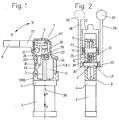
- the reference numeral 1 designates a clamping head on which an axially one Cylinder 2 connects, in the longitudinally displaceable and sealing a not shown Piston is arranged.
- the cylinder 2 is in the illustrated embodiment flat oval, so that the piston is designed accordingly.
- a piston rod 3 is connected, the cylinder 2 and Clamping head 1 reaches partially axially.
- the piston rod 3 also penetrates a cover 4, in which it is sealed by a seal, not shown is led.
- FIG. 1 in particular shows that the piston rod 3 is connected at its end to a toggle joint arrangement 5 which is a Clamping arm 6 is assigned.
- This clamping arm 6 is in the direction X or Y after the piston has been pressurized with air pressure.
- the opening angle this tension arm can be variable and for example maximum 135 degrees.
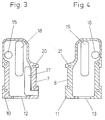
- the clamping head 1 has a housing on, which consists of two shell-shaped housing parts 7 and 8, the sandwich tightly together.
- the housing parts 7 and 8 are through a straight dividing plane 9 separated from each other, so that the Housing parts 7 and 8 lie flat on one another through walls 10 and 11 and detachably and tightly connected by screws (not shown) are.
- the shell-shaped housing parts 7 and 8 are closed on all sides and each have an approximately semicircular recess on one side 12 or 13, which thus complement each other to form a hole through which the piston rod 3 in the space delimited by the housing parts 7 and 8 14 protrude.
- the toggle joint arrangement 5 is also in this space 14 arranged. The end of the piston rod 3 located within the space 14 and the toggle joint arrangement 5 are thus dirt, dust and spray liquid tight encapsulated to the outside.
- the two shell-shaped housing parts 7 and 8 each have one orthogonal penetrating bore 15 and 16 through which a pivot pin 17 for the toggle joint arrangement 5 reaches through.
- the two shell-shaped housing parts 7 and 8 each have one Guide groove 18 and 19.
- the guide grooves 18 and 19 are of the same design and correspond in the assembled state of the housing parts 7 and 8 with each other, such that the toggle joint arrangement 5 is associated with Components is guided in the longitudinal axis direction. You can do this, for example at each end of a pivot pin, not shown in detail arranged roles are used. Of these pivot pins is only centerline 40 is located in the drawing. At each end of the pivot pin 2 one of these guide rollers can be provided, each in one of the guide grooves 18 and 19 are guided.
- the roles can be the same size and be arranged coaxially to one another, so that there is a smooth operation results when pivoting the toggle joint arrangement 5 and this reliably to be led.
- holes are designated. These holes, for example 20, can be designed as through holes, while the assigned, Bores 21 of the other housing part arranged coaxially to this Make 8 blind holes with threads. By screwing in not shown bolts can thereby the housing parts 7 and 8th Detachable, but tightly and extensively connected.
- the housing parts 7 and 8 can be made of steel or aluminum or another suitable material, for example made of an injection molding material.
- the walls 10 and 11 are of high quality, for example ground or cast or injection molded with the appropriate surface so that they are full and tightly sealed to each other to the required dust and To maintain splash water resistance.
- the reference numeral 22 denotes a fork arm, which has its ends on end sections which are square or polygonal in cross section 23 or 24 is arranged. With 25 and 26 holding tabs are designated, which attack against the fork-shaped end of the associated fork arm 22 and with formally adapted recesses, the end sections 23 and 24, respectively of the pivot pin 17 and grip with the fork arm 22 in question are connected by screws (not shown).
- the fork arm 22 can have a screw-on part that is centered in relation is arranged on the fork arm. But it is also possible to use the fork arm assign eccentric screw-on part, for example this screw-on part to be provided on the left or right. This way you can look at each Adjust the space and installation conditions.
- a cassette is located at 27.
- This cassette can be exchangeable unit or board can be formed and includes limit switches, Microswitches or inductive switches or pneumatic switches for Query of the respective position of the piston and thus also the position of the Arm 6.
- the reference number 28 can be used on both sides of the device Hand lever designated, which has a handle 29. 2 is with dash-dotted lines represent the alternative attachment arrangement for this hand lift 28 have been shown.
- This hand lever 28 has a clutch 30, by means of which the hand lever 28 can be plugged onto a pivot axis 31 which is pivotally mounted in the housing parts 7 and 8.
- the housing parts 7 and 8 have bores arranged coaxially to one another on, from which the pivot axis 31 with its two ends around one Dimension protrudes that the clutch 30 of the hand lever 28 can be plugged on.
- the pivot axis 31 with suitable profiles, For example, a square or hexagon on which the coupling 30 with a corresponding, adapted shape (not shown) attachable is to create a positive connection.
- pivot axis 31 can be sealed in a suitable manner Bores of the housing parts 7 and 8 can be led out, for example Seals, not shown, to the required dirt and dust tightness and if necessary to achieve a liquid-tight encapsulation.
- an articulated lever 32 is in one piece arranged, which is approximately S-shaped in the plan view shown in FIG. 1 is formed and consists of two lengths, which in the illustrated Embodiment with their longitudinal axes perpendicular to each other.
- the one, in length larger dimensioned length section 33 is with the Pivot axis 31 connected in one piece, while the other longitudinal section 34 at its end in the illustrated embodiment, a ball trained driver 35 which slides in a backdrop 36 and is arranged pivotably or unrollable.
- This backdrop 36 is in the embodiment shown by an orthogonal with its longitudinal axis 37 to the longitudinal axis 38 of the piston rod 3 extending bore formed in the the rigid driver 35 slidably and unrollable and suitable, but with the required game, is arranged.
- the driver 35 is rigid and integrally connected to the length section 34. Both the Swivel axis 31, as well as the longitudinal sections 33 and 34, but also the Carriers 35 can be made of a metallic material, primarily Steel.
- the driver 35 has the required surface quality, to allow smooth movement in the backdrop 36. How from 1 shows the backdrop 36 with a thickening of the piston rod 3 also integrally connected in terms of material, in which the hole is formed Backdrop 36 is arranged.
- a symmetrical to the longitudinal axis 38 of the Piston rod 3 extending slot 39 into which the articulated lever 32 with its length sections 33 and 34 in a form-fitting manner, but with play can, if the piston rod 3 in the longitudinal axis direction A or B (Fig. 1) shifted becomes.
- the articulated lever 32 is rectangular in cross section, thus plate-like, trained. For example, if you run an orthogonal one cross section directed to the longitudinal axis of the longitudinal section 33, so this flat rectangular. This also applies accordingly to the length segment 34 with a cross section guided orthogonally to its longitudinal axis.
- Both cross sections of the longitudinal sections 33 and 34 are identical in shape formed so that the length sections 33 and 34 without jumping into each other pass over and are even on both sides.
- the manual adjustment of the tension arm 6 is done via the hand lever 28, in which this up and down in the required manner, ie in Is pivoted in the X or Y direction.
- This also turns the swivel axis 31 rotated accordingly about its longitudinal axis, whereby the one-piece connected Articulated lever 32 is taken along and the piston rod via the driver 35 3 moved in direction A or B.
- the driver 35 only slides orthogonal to the longitudinal axis 38 of the piston rod 3, that is to say in the link 36 and forth.
- the articulated lever 32 plunges more or less deep into the slot 39 a.
- control means such as multi-way valves, etc., for the pressure medium supply serve to one or the other side of the piston are for the sake of Simplification not shown, but can correspond to conventional designs.
Landscapes
- Engineering & Computer Science (AREA)
- Mechanical Engineering (AREA)
- Jigs For Machine Tools (AREA)
- Gripping Jigs, Holding Jigs, And Positioning Jigs (AREA)
- Silver Salt Photography Or Processing Solution Therefor (AREA)
- Mechanical Control Devices (AREA)
Claims (16)
- Dispositif de serrage à genouillère, utilisable en particulier dans les dispositifs et machines à souder employés par l'industrie automobile pour construire les carrosseries, présentant une tête de serrage (1) et un vérin (2) raccordé à la tête pour en former le prolongement axial, vérin dans lequel se meut longitudinalement et alternativement dans les deux sens sous l'effet de la pression d'un fluide sous pression, de l'air comprimé de préférence, un piston étanchant dont la tige (3) traverse le vérin (2) et une tête de serrage (1) raccordée à ce dernier (2) dans le sens axial, un ensemble articulé à genouillère (5) étant fixé contre l'extrémité libre de la tige de piston (3) à l'intérieur du boítier, ensemble auquel est affecté un bras de serrage (6), la tête de serrage (1) se composant de deux pièces de boítier (7, 8) en forme de coquilles en matériau monobloc, ces pièces enveloppant l'ensemble articulé à genouillère (5) et une partie de la tige (3) du piston pour les protéger de la poussière, des salissures et des projections, sachant que dans les parois intérieures des pièces du boítier (7, 8) en forme de coquilles des rainures de guidage (18, 19) ont été ménagées pour les ensembles articulés à genouillère (5), que des alésages traversants (15, 16) ont été ménagés pour laisser passage à un goujon pivotant (17) de l'ensemble articulé à genouillère (5) et que le cas échéant au moins une ouverture ou un évidement a été ménagé(e) pour recevoir une cassette (27), des microcommutateurs ou des commutateurs inductifs ou des commutateurs pneumatiques, caractérisé par un levier manuel (28) attaquant la tige (3) du piston et actionnable à la main par la poignée (29) qui lui (28) est affectée, ce levier manuel (28) agissant de concert avec la tige (3) du piston via une articulation pour engendrer le mouvement axial de la tige, le lever manuel (28) étant disposé sur un axe de pivotement (31) affecté à la tête de serrage, et par le fait que l'axe de pivotement (31) est relié à un taquet entraíneur (35) via un levier articulé (32), lequel (35) est directement guidé et retenu dans une coulisse (36) que présente la tige (3) du piston.
- Dispositif de serrage à genouillère selon la revendication 1, caractérisé en ce que la coulisse (36) que présente la tige (3) du piston pour guider le taquet entraíneur (35) a un tracé transversal par rapport à l'axe longitudinal (38) de la tige (3) du piston.
- Dispositif de serrage à genouillère selon la revendication 2, caractérisé en ce que la coulisse (36) a un tracé rectiligne et perpendiculaire à l'axe longitudinal (38) de la tige (3) du piston.
- Dispositif de serrage à genouillère selon la revendication 1 ou l'une des revendications suivantes, caractérisé en ce que le taquet entraíneur (35) rigide est guidé dans la coulisse (36) de la tige (3) du piston de sorte à pouvoir glisser et pivoter dedans.
- Dispositif de serrage à genouillère selon la revendication 1 ou l'une des revendications suivantes, caractérisé en ce que la coulisse (36) est en forme d'alésage et en ce que le taquet entraíneur (35) a une géométrie bombée ou torique.
- Dispositif de serrage à genouillère selon la revendication 1 ou l'une des revendications 2 à 4, caractérisé en ce que le taquet entraíneur (35) a la forme d'une calotte sphérique.
- Dispositif de serrage à genouillère selon la revendication 1 ou l'une des revendications 2 à 4, caractérisé en ce que le taquet entraíneur (35) est une sphère partielle.
- Dispositif de serrage à genouillère selon la revendication 1 ou l'une des revendications 2 à 5, caractérisé en ce que le taquet entraíneur (35) est une sphère.
- Dispositif de serrage à genouillère selon la revendication 1 ou l'une des revendications suivantes, caractérisé en ce que dans la zone médiane de la coulisse (36) a été ménagée une fente (39) aux dimensions limitées s'étendant dans le sens axial de la tige du piston (3), fente dans laquelle le lever articulé (32) plonge en se modifiant entièrement ou partiellement lorsque la tige (3) du piston se déplace.
- Dispositif de serrage à genouillère selon la revendication 1 ou l'une des suivantes, caractérisé en ce que le levier articulé (32) est relié monobloc et de manière rigide d'une part avec l'axe pivotant (31) et d'autre part avec le taquet entraíneur (35).
- Dispositif de serrage à genouillère selon la revendication 1 ou l'une de suivantes, caractérisé en ce que le lever articulé (32) se compose de deux pièces du levier (33, 34) en forme de segments longitudinaux formant un angle l'une par rapport à l'autre, l'un (34) des segments longitudinaux étant relié au taquet entraíneur (35) et l'autre (33) segment longitudinal étant relié par son extrémité à l'axe pivotant (31).
- Dispositif de serrage à genouillère selon la revendication 11, caractérisé en ce qu'en position de serrage ou approximativement en position de serrage l'une (33) des pièces du lever a un tracé parallèle à l'axe longitudinal (38) de la tige (3) du piston et en ce que l'autre (34) pièce du levier a un tracé perpendiculaire ou approximativement perpendiculaire à l'axe longitudinal (38).
- Dispositif de serrage à genouillère selon la revendication 1 ou l'une des suivantes, caractérisé en ce que le taquet entraíneur (35) décrit un mouvement transversal, de préférence perpendiculaire à l'axe longitudinal (38) du piston (3) lorsque le bras de serrage (6) pivote dans les deux sens, tandis que le levier articulé (32) pivote dans un plan parallèle ou approximativement parallèle à l'axe longitudinal (38) de la tige (3) du piston.
- Dispositif de serrage à genouillère selon la revendication 11 ou l'une des suivantes, caractérisé en ce que le lever articulé (32) vu de côté a une géométrie approximativement en "S" et en ce qu'à l'une de ses extrémités il présente l'axe de pivotement (31) et à l'autre extrémité le taquet entraíneur (35).
- Dispositif de serrage à genouillère selon la revendication 11 ou l'une des suivantes, caractérisé en ce que le levier articulé (32) a la forme d'une plaque et qu'il engrène exactement mais avec du jeu dans la fente (39) de la tige (3) du piston, la fente longitudinale (39) débouchant perpendiculairement dans la coulisse (36), et en ce que l'axe longitudinal du levier articulé (32) a un tracé perpendiculaire à l'axe longitudinal de l'axe (31) par lequel pivote le lever manuel (28).
- Dispositif de serrage à genouillère selon la revendication 1 ou l'une des suivantes, caractérisé en ce que le goujon pivotant (17) de l'ensemble articulé à genouillère (5) comporte à chaque extrémité au moins un galet de guidage et en ce que chacun de ces galets de guidage est logé, pour y rouler, dans l'une des rainures de guidage (18, 19) ménagées dans les pièces-coquilles (7 et 8) formant le boítier.
Applications Claiming Priority (2)
| Application Number | Priority Date | Filing Date | Title |
|---|---|---|---|
| DE29516531U DE29516531U1 (de) | 1995-10-19 | 1995-10-19 | Kniehebelspannvorrichtung |
| DE29516531U | 1995-10-19 |
Publications (2)
| Publication Number | Publication Date |
|---|---|
| EP0769353A1 EP0769353A1 (fr) | 1997-04-23 |
| EP0769353B1 true EP0769353B1 (fr) | 1999-03-10 |
Family
ID=8014312
Family Applications (1)
| Application Number | Title | Priority Date | Filing Date |
|---|---|---|---|
| EP96107559A Expired - Lifetime EP0769353B1 (fr) | 1995-10-19 | 1996-05-11 | Dispositif de serrage à grenouillère |
Country Status (4)
| Country | Link |
|---|---|
| US (1) | US5823519A (fr) |
| EP (1) | EP0769353B1 (fr) |
| DE (2) | DE29516531U1 (fr) |
| ES (1) | ES2130715T3 (fr) |
Cited By (1)
| Publication number | Priority date | Publication date | Assignee | Title |
|---|---|---|---|---|
| DE202014102804U1 (de) | 2014-05-22 | 2014-07-29 | Pepperl + Fuchs Gmbh | Geber für Kraftspanner |
Families Citing this family (25)
| Publication number | Priority date | Publication date | Assignee | Title |
|---|---|---|---|---|
| DE19645778C2 (de) * | 1996-11-07 | 1999-07-08 | Sta Co Mettallerzeugnisse Gmbh | Kniehebel-Spannvorrichtung |
| DE10124063A1 (de) * | 2001-05-16 | 2002-11-28 | Sta Co Mettallerzeugnisse Gmbh | Spannvorrichtung zum gegenseitigen Festspannen insbesondere von per Laser zu verschweißenden Karosserieteilrändern |
| US6666489B2 (en) * | 2001-08-23 | 2003-12-23 | Btm Corporation | Sealed gripper apparatus |
| FR2834661B1 (fr) * | 2002-01-17 | 2004-06-18 | Genus Technologies | Dispositif de serrage, en particulier pour pieces de carrosserie automobile |
| US6786478B2 (en) * | 2002-07-10 | 2004-09-07 | Welker Bearing Company | Locating assembly having an extendable clamping finger |
| ITMI20021914A1 (it) * | 2002-09-10 | 2004-03-11 | Univer Spa | Dispositivo di bloccaggio con leva manuale di comando |
| US7815176B2 (en) | 2003-09-11 | 2010-10-19 | Phd, Inc. | Lock mechanism for pin clamp assembly |
| ITTO20030813A1 (it) * | 2003-10-16 | 2005-04-17 | Vep Automation Srl | Dispositivo di chiusura a leva articolata per il bloccaggio di pezzi. |
| US20070023410A1 (en) * | 2003-11-24 | 2007-02-01 | Miguel Sarabia Trilla | Clamping jaw for automated welding installations |
| US7182326B2 (en) * | 2004-04-02 | 2007-02-27 | Phd, Inc. | Pin clamp |
| US7516948B2 (en) | 2004-04-02 | 2009-04-14 | Phd, Inc. | Pin clamp accessories |
| FR2871715B1 (fr) * | 2004-06-22 | 2007-10-05 | Robotic Sa | Dispositif de serrage d'une piece de construction a usiner |
| US7448607B2 (en) | 2004-12-15 | 2008-11-11 | Phd, Inc. | Pin clamp assembly |
| DE202005004598U1 (de) * | 2005-03-18 | 2006-07-27 | De-Sta-Co Europe Gmbh | Spannvorrichtung |
| JP4892668B2 (ja) * | 2007-02-15 | 2012-03-07 | Smc株式会社 | クランプ装置 |
| ES2707249T3 (es) | 2007-06-19 | 2019-04-03 | Phd Inc | Conjunto de abrazadera de pasador |
| JP2009233695A (ja) * | 2008-03-26 | 2009-10-15 | Fujitsu Ltd | ハンドプレス機 |
| MX2010014266A (es) | 2008-06-18 | 2011-03-29 | Phd Inc Star | Sujetador con perno de extraccion. |
| DE102010043574A1 (de) * | 2010-11-08 | 2012-05-10 | Fresenius Medical Care Deutschland Gmbh | Manuell zu öffnender Klemmhalter mit Sensor |
| US10625382B2 (en) * | 2012-08-01 | 2020-04-21 | Delaware Capital Formation, Inc. | Toggle lever clamp |
| WO2017016607A1 (fr) * | 2015-07-30 | 2017-02-02 | Pneumax S.P.A. | Dispositif d'actionnement du type doté d'un élément d'actionnement et de moyens de commande manuelle de l'élément d'actionnement |
| EP3375569A1 (fr) * | 2017-03-13 | 2018-09-19 | UNIVER S.p.A. | Dispositif de positionnement, de pivotement ou de serrage de pièces usinées |
| CN106862845A (zh) * | 2017-04-21 | 2017-06-20 | 大连爱渥特机器人科技有限公司 | 一种白车身焊装夹具定位夹紧机构 |
| US11759915B2 (en) | 2021-10-03 | 2023-09-19 | Delaware Capital Formation, Inc. | Pneumatic latch clamp |
| CN114290092A (zh) * | 2022-01-29 | 2022-04-08 | 苏州普来可瑞机电技术有限公司 | 单连杆防异物杠杆缸与夹紧装置 |
Family Cites Families (41)
| Publication number | Priority date | Publication date | Assignee | Title |
|---|---|---|---|---|
| DE156107C (fr) * | ||||
| DD30739A (fr) * | ||||
| DE8307606U1 (de) * | 1983-08-04 | De-Sta-Co Metallerzeugnisse Gmbh, 6000 Frankfurt | Kniehebelspannvorrichtung | |
| DE550737C (de) * | 1929-10-27 | 1932-05-19 | Daimler Benz Akt Ges | Vorrichtung zum Befestigen von Tuch, Leder, Kunstleder o. dgl. auf Holzteilen bei Moebeln, im Karosseriebau usw. |
| DE708439C (de) * | 1939-11-15 | 1941-07-21 | Gerhard Fieseler | Pressluftspannzwinge |
| US2683386A (en) * | 1952-06-21 | 1954-07-13 | Specken Ag | Fluid-pressure-operated vise having displaceable cylinder and adjustable piston |
| DE1016128B (de) * | 1955-12-07 | 1957-09-19 | Burger & Soehne O H G | Druckluft-Kniehebelpresse |
| GB814938A (en) * | 1956-12-12 | 1959-06-17 | Waldes Kohinoor Inc | Improvements in or relating to devices for dispensing open retaining rings and applying them to grooved members |
| US2914977A (en) * | 1958-09-19 | 1959-12-01 | Verderber Joseph | Fluid-actuated clamping device |
| DE1171350B (de) * | 1958-11-12 | 1964-05-27 | Emil Arnold | Spannzeug |
| DE1176969B (de) * | 1960-12-10 | 1964-08-27 | Schwermaschb Iaheinrich Rauia | Biegevorrichtung, insbesondere fuer Zangen-schenkelschmiedeautomaten |
| US3116058A (en) * | 1961-03-31 | 1963-12-31 | Leland F Blatt | Cylinder operated power clamp |
| FR1405779A (fr) * | 1964-08-28 | 1965-07-09 | Etau | |
| US3371923A (en) * | 1965-08-17 | 1968-03-05 | Leland F. Blatt | Mount for cylinder operated power clamp |
| FR1477602A (fr) * | 1966-03-03 | 1967-04-21 | Gaillon Armovyl Soc Ind | Nouveau dispositif pour maintenir des éléments de tubes de diamètres différents sur un axe prédéterminé |
| US3482830A (en) * | 1966-04-05 | 1969-12-09 | Jack J Sendoykas | Clamp |
| DE1268074B (de) * | 1966-06-23 | 1968-05-09 | Blatt Leland F | Greifbacke |
| US3570835A (en) * | 1968-10-08 | 1971-03-16 | Dover Corp | Power operated clamping device |
| US3545050A (en) * | 1969-01-30 | 1970-12-08 | I S I Mfg Inc | Power clamp with pull-back action |
| DE1917295A1 (de) * | 1969-04-03 | 1970-10-22 | Automotive Prod Co Ltd | Lukendeckel |
| US3599957A (en) * | 1969-04-28 | 1971-08-17 | Leland F Blatt | Cam wedge power swing away with guided arm |
| GB1221037A (en) * | 1969-08-21 | 1971-02-03 | Blatt Leland F | Toggle action jaw type gripper |
| DE2129750C3 (de) * | 1971-06-16 | 1974-05-02 | Suevia Haiges Kg, 7125 Kirchheim | Hydraulisch oder pneumatisch betätigbare Spannvorrichtung oder dergleichen |
| US3801091A (en) * | 1972-01-31 | 1974-04-02 | Dover Corp | Universal clamp with adjustable retention means |
| DE2222686B2 (de) * | 1972-05-09 | 1980-06-12 | Tuenkers Maschinenbau Gmbh, 4030 Ratingen | Druckmittelbetatigte Kniehebelspannvorrichtung, insbesondere für Karosserieteile |
| US3872760A (en) * | 1973-07-12 | 1975-03-25 | Jr George J Desnoyers | Tool and method of using same |
| FR2409819A1 (fr) * | 1977-11-29 | 1979-06-22 | Cecchi Gerard | Dispositif de serrage a commande pneumatique |
| DE2813694C2 (de) * | 1978-03-30 | 1981-09-17 | Tünkers Maschinenbau GmbH, 4030 Ratingen | Druckmittelbetätigbare Kniehebelspannvorrichtung mit einem dopptelt wirkenden Spannzylinder, in dem ein Differentialkolben längsverschiebbar geführt ist |
| DE2904378C2 (de) * | 1979-02-06 | 1983-04-28 | ASEA AB, 72183 Västeraas | Zangengreifarm zum Stützen und Greifen langer zylindrischer Werkstücke an Werkzeugmaschinen |
| US4257583A (en) * | 1980-02-29 | 1981-03-24 | Carson James W | Clamping device |
| DE3130942A1 (de) * | 1981-08-05 | 1983-04-28 | Tünkers Maschinenbau GmbH, 4030 Ratingen | Druckmittelbetaetigbare kniehebelspannvorrichtung mit elastischem federgelenk und loesbar befestigtem spannarm |
| US4458889A (en) * | 1982-09-29 | 1984-07-10 | Dover Corporation (De-Sta-Co. Div.) | Locking power clamp |
| US4637597A (en) * | 1982-09-29 | 1987-01-20 | De-Sta-Co Division/Dover Corporation | Locking power clamp |
| US4620696A (en) * | 1983-08-10 | 1986-11-04 | Blatt Leland F | Power clamp |
| DE3513680C2 (de) * | 1985-04-16 | 1989-07-20 | Josef Gerhard 4030 Ratingen Tünkers | Druckmittelbetätigbare Kniehebelspannvorrichtung zum Festspannen von Werkstücken |
| DE8606451U1 (de) * | 1986-03-08 | 1986-06-12 | De-Sta-Co Metallerzeugnisse Gmbh, 6000 Frankfurt | Kniehebelspannvorrichtung |
| DE3613852C1 (de) * | 1986-04-24 | 1987-10-01 | Tuenkers Josef Gerhard | Druckmittelbetaetigbare Kniehebelspannvorrichtung |
| US5171001A (en) * | 1987-05-27 | 1992-12-15 | Btm Corporation | Sealed power clamp |
| US4854564A (en) * | 1988-08-29 | 1989-08-08 | Delaware Capital Formation, Inc. | Power clamp with track wiper |
| US4887803A (en) * | 1989-01-09 | 1989-12-19 | Witt Larry M | Power actuated cam clamp |
| DE29504267U1 (de) * | 1995-03-13 | 1995-06-29 | Tünkers Maschinenbau GmbH, 40880 Ratingen | Kniehebelspannvorrichtung, insbesondere zur Verwendung im Karosseriebau der Kfz-Industrie |
-
1995
- 1995-10-19 DE DE29516531U patent/DE29516531U1/de not_active Expired - Lifetime
-
1996
- 1996-05-11 EP EP96107559A patent/EP0769353B1/fr not_active Expired - Lifetime
- 1996-05-11 DE DE59601413T patent/DE59601413D1/de not_active Expired - Lifetime
- 1996-05-11 ES ES96107559T patent/ES2130715T3/es not_active Expired - Lifetime
- 1996-10-21 US US08/734,640 patent/US5823519A/en not_active Expired - Lifetime
Cited By (5)
| Publication number | Priority date | Publication date | Assignee | Title |
|---|---|---|---|---|
| DE202014102804U1 (de) | 2014-05-22 | 2014-07-29 | Pepperl + Fuchs Gmbh | Geber für Kraftspanner |
| DE102014107267A1 (de) | 2014-05-22 | 2015-11-26 | Pepperl + Fuchs Gmbh | Geber für Kraftspanner |
| WO2015177291A1 (fr) | 2014-05-22 | 2015-11-26 | Pepperl + Fuchs Gmbh | Capteur pour dispositif de serrage électrique |
| DE102014107267B4 (de) | 2014-05-22 | 2019-06-13 | Pepperl + Fuchs Gmbh | Kniehebelspannvorrichtung mit Abfrageeinheit sowie Abfrageeinheit für eine vereinfachte Montage |
| US10688626B2 (en) | 2014-05-22 | 2020-06-23 | Pepperl+Fuchs Gmbh | Sensor for power clamp |
Also Published As
| Publication number | Publication date |
|---|---|
| DE59601413D1 (de) | 1999-04-15 |
| DE29516531U1 (de) | 1995-12-14 |
| EP0769353A1 (fr) | 1997-04-23 |
| US5823519A (en) | 1998-10-20 |
| ES2130715T3 (es) | 1999-07-01 |
Similar Documents
| Publication | Publication Date | Title |
|---|---|---|
| EP0769353B1 (fr) | Dispositif de serrage à grenouillère | |
| DE102009005543B4 (de) | Spannvorrichtung mit zwei Paaren von Drehwalzen an einem Verschiebungskörper | |
| EP0803331B1 (fr) | Dispositif de serrage à genouillère pour la construction en carrosserie | |
| DE69835836T2 (de) | Universalgreifer mit Anschlagelemente für gegriffene Werkstücke | |
| DE19824579C1 (de) | Kniehebelspannvorrichtung, insbesondere zur Verwendung im Karosseriebau der Kfz-Industrie | |
| DE112013003482B4 (de) | Spannvorrichtung | |
| DE69916063T2 (de) | Entfernbare schraubstopfen und werkzeug | |
| EP2329153B1 (fr) | Dispositif à entraînement par air comprimé, équipé d'une fonction double piston et destiné à être utilisé dans le domaine de la carrosserie pour l'industrie automobile | |
| DE29718643U1 (de) | Druckmittelbetätigbare kombinierte Zentrier- und Spannvorrichtung, insbesondere zur Verwendung im Karosseriebau der Kfz-Industrie | |
| DE3610317A1 (de) | Automatische zentrier- und greifvorrichtung | |
| DE69408881T2 (de) | Fahrrad-Werkzeug | |
| DE4042070A1 (de) | Druckmittelbetriebener kraftschrauber | |
| DE102004040606B3 (de) | Als Gripper ausgebildete Kniehebelspannvorrichtung, insbesondere zur Verwendung im Karosseriebau der Kfz-Industrie | |
| DE202009002141U1 (de) | Vorrichtung mit einem über ein Stellglied und einer Kniehebelgelenkanordnung durch einen Antrieb in entgegengesetzten Richtungen antreibbaren Hebel, dem eine oder mehrere Massen zugeordnet ist bzw. sind, insbesondere zur Verwendung im Karosseriebau der Kfz-Industrie | |
| DE29701730U1 (de) | Kniehebelspannvorrichtung, insbesondere zur Verwendung in Vorrichtungen und Schweißmaschinen des Karosseriebaus der Kfz-Industrie | |
| EP1055589B1 (fr) | Support pour un spoiler disposé sur le toit de la cabine conducteur d'un camion | |
| DE102010024907A1 (de) | Linearstellglied | |
| DE3613852C1 (de) | Druckmittelbetaetigbare Kniehebelspannvorrichtung | |
| DE29504267U1 (de) | Kniehebelspannvorrichtung, insbesondere zur Verwendung im Karosseriebau der Kfz-Industrie | |
| EP0136492B1 (fr) | Moteur à piston oscillant | |
| DE202004019495U1 (de) | Durch Druckmitteldruck, insbesondere pneuamtisch, betätigte Kolben-Zylinder-Einheit, bei welcher ein mit einer Kolbenstange verbundener Kolben durch Druckmittelbeaufschlagung linear bewegbar ist, z.B. druckmittelbetätigbare Kniehebelspannvorrichtung, insbesondere für den Karosseriebau der Kfz-Industrie | |
| EP0928664A2 (fr) | Dispositif à genouillère actionné à main | |
| EP1442832B1 (fr) | Dispositif de serrage pour serrer un boulon d'ancrage d'alimentation latèral des boules de serrage | |
| DE4413560C2 (de) | Hydraulik-Steuervorrichtung für Rettungsgeräte | |
| DE102018003877B4 (de) | Variable Zentriervorrichtung für blechförmige Bauteile der Kfz-Industrie |
Legal Events
| Date | Code | Title | Description |
|---|---|---|---|
| PUAI | Public reference made under article 153(3) epc to a published international application that has entered the european phase |
Free format text: ORIGINAL CODE: 0009012 |
|
| 17P | Request for examination filed |
Effective date: 19960528 |
|
| AK | Designated contracting states |
Kind code of ref document: A1 Designated state(s): DE ES FR GB IT SE |
|
| 17Q | First examination report despatched |
Effective date: 19971105 |
|
| GRAG | Despatch of communication of intention to grant |
Free format text: ORIGINAL CODE: EPIDOS AGRA |
|
| GRAG | Despatch of communication of intention to grant |
Free format text: ORIGINAL CODE: EPIDOS AGRA |
|
| GRAH | Despatch of communication of intention to grant a patent |
Free format text: ORIGINAL CODE: EPIDOS IGRA |
|
| GRAH | Despatch of communication of intention to grant a patent |
Free format text: ORIGINAL CODE: EPIDOS IGRA |
|
| GRAH | Despatch of communication of intention to grant a patent |
Free format text: ORIGINAL CODE: EPIDOS IGRA |
|
| GRAA | (expected) grant |
Free format text: ORIGINAL CODE: 0009210 |
|
| ITF | It: translation for a ep patent filed | ||
| AK | Designated contracting states |
Kind code of ref document: B1 Designated state(s): DE ES FR GB IT SE |
|
| REF | Corresponds to: |
Ref document number: 59601413 Country of ref document: DE Date of ref document: 19990415 |
|
| REG | Reference to a national code |
Ref country code: ES Ref legal event code: FG2A Ref document number: 2130715 Country of ref document: ES Kind code of ref document: T3 |
|
| GBT | Gb: translation of ep patent filed (gb section 77(6)(a)/1977) |
Effective date: 19990614 |
|
| ET | Fr: translation filed | ||
| PLBE | No opposition filed within time limit |
Free format text: ORIGINAL CODE: 0009261 |
|
| STAA | Information on the status of an ep patent application or granted ep patent |
Free format text: STATUS: NO OPPOSITION FILED WITHIN TIME LIMIT |
|
| 26N | No opposition filed | ||
| REG | Reference to a national code |
Ref country code: GB Ref legal event code: IF02 |
|
| REG | Reference to a national code |
Ref country code: FR Ref legal event code: PLFP Year of fee payment: 20 |
|
| PGFP | Annual fee paid to national office [announced via postgrant information from national office to epo] |
Ref country code: SE Payment date: 20150512 Year of fee payment: 20 Ref country code: DE Payment date: 20150506 Year of fee payment: 20 Ref country code: GB Payment date: 20150506 Year of fee payment: 20 Ref country code: ES Payment date: 20150413 Year of fee payment: 20 |
|
| PGFP | Annual fee paid to national office [announced via postgrant information from national office to epo] |
Ref country code: IT Payment date: 20150515 Year of fee payment: 20 Ref country code: FR Payment date: 20150508 Year of fee payment: 20 |
|
| REG | Reference to a national code |
Ref country code: DE Ref legal event code: R071 Ref document number: 59601413 Country of ref document: DE |
|
| REG | Reference to a national code |
Ref country code: GB Ref legal event code: PE20 Expiry date: 20160510 |
|
| PG25 | Lapsed in a contracting state [announced via postgrant information from national office to epo] |
Ref country code: GB Free format text: LAPSE BECAUSE OF EXPIRATION OF PROTECTION Effective date: 20160510 |
|
| REG | Reference to a national code |
Ref country code: ES Ref legal event code: FD2A Effective date: 20160826 |
|
| PG25 | Lapsed in a contracting state [announced via postgrant information from national office to epo] |
Ref country code: ES Free format text: LAPSE BECAUSE OF EXPIRATION OF PROTECTION Effective date: 20160512 |