EP0769355A1 - Schneidgerät für Kunststoffflaschen - Google Patents
Schneidgerät für Kunststoffflaschen Download PDFInfo
- Publication number
- EP0769355A1 EP0769355A1 EP96307308A EP96307308A EP0769355A1 EP 0769355 A1 EP0769355 A1 EP 0769355A1 EP 96307308 A EP96307308 A EP 96307308A EP 96307308 A EP96307308 A EP 96307308A EP 0769355 A1 EP0769355 A1 EP 0769355A1
- Authority
- EP
- European Patent Office
- Prior art keywords
- blade
- covering member
- plastic bottle
- cutting implement
- grip part
- Prior art date
- Legal status (The legal status is an assumption and is not a legal conclusion. Google has not performed a legal analysis and makes no representation as to the accuracy of the status listed.)
- Withdrawn
Links
- 229920003023 plastic Polymers 0.000 title claims abstract description 73
- 239000004033 plastic Substances 0.000 title claims abstract description 73
- 238000005516 engineering process Methods 0.000 description 2
- 229920000122 acrylonitrile butadiene styrene Polymers 0.000 description 1
- 239000012141 concentrate Substances 0.000 description 1
- 238000010276 construction Methods 0.000 description 1
- 230000007423 decrease Effects 0.000 description 1
- 238000007373 indentation Methods 0.000 description 1
- 239000000463 material Substances 0.000 description 1
- 238000000034 method Methods 0.000 description 1
- 239000002991 molded plastic Substances 0.000 description 1
- 238000003825 pressing Methods 0.000 description 1
- 239000010924 used plastic bottle Substances 0.000 description 1
Images


Classifications
-
- B—PERFORMING OPERATIONS; TRANSPORTING
- B26—HAND CUTTING TOOLS; CUTTING; SEVERING
- B26B—HAND-HELD CUTTING TOOLS NOT OTHERWISE PROVIDED FOR
- B26B27/00—Hand cutting tools not provided for in the preceding groups, e.g. finger rings for cutting string, devices for cutting by means of wires
Definitions
- This invention relates to a plastic bottle cutting implement for cutting a blow-molded plastic bottle.
- Known implements for cutting plastic bottles such as PET bottles include that disclosed by the present inventors in Japanese Utility Model Publication No. 3006155.
- This cutting implement has a cylindrical covering member which fits with slight looseness around the outside of a plastic bottle, and a bar-shaped grip part is attached to the outer side of this covering member and projects outward.
- a blade for cutting is provided on the inner side of the covering member projecting in a direction perpendicular to the center axis of the covering member.
- This plastic bottle cutting implement is used by first inserting a plastic bottle inside the covering member and pressing the blade through the side wall of the plastic bottle. Then, while the grip part is held, the plastic bottle is rotated about its center axis so that it is pushed onto the blade and the plastic bottle is thereby cut.
- the line along which the plastic bottle is cut by the plastic bottle cutting implement makes a circumference of the side wall of the plastic bottle and the plastic bottle is thereby cut into two pieces. When this is repeated several times, the plastic bottle is cut into several ring-shaped side wall pieces and a top piece and a bottom piece, its volume decreases and space can therefore be saved when it is disposed of.
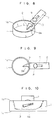
- the blade 3 is inserted in a direction perpendicular to the side wall 21 of the plastic bottle 20, i.e. in the inside-outside direction of the side wall 21, to cut the plastic bottle 20.
- both sides of the blade 3 are gripped by the side wall 21 and a very large frictional force acts on it, and a strong force has been required for the cutting.
- the frictional resistance is large, there has been the problem that wear of the blade edge 3a is severe and it is necessary to replace the blade 3 frequently.
- the present invention was made in view of the problem points of the related art technology described above, and an object of the invention is to provide a plastic bottle cutting implement with which it is possible to reliably cut a plastic bottle efficiently.
- the invention provides a plastic bottle cutting implement comprising a preferably cylindrical or part-cylindrical covering member and a blade disposed projecting from the inside surface of this covering member, wherein the direction in which the blade projects makes any angle other than perpendicular or parallel with respect to the imaginary center axis of the cylindrical part of the covering member.
- a grip member may be attached to the outer side of the covering member.
- the grip member may be bar-shaped and mounted projecting from the outer side of the covering member. There may be a hollow part connecting with the inside surface of the covering member is formed inside the grip member. Inside this hollow part may be disposed a sliding fitting slidable inside the hollow part and fixable in any position inside the hollow part and a blade having one end thereof attached to the sliding fitting.
- the grip member may be formed foldably with respect to the covering member and foldable to inside the covering member.
- the direction in which the blade cuts intersects diagonally with a plane orthogonal to the imaginary center axis of the covering member.
- the edge of the blade may be formed in an arcuate concave shape in the cross-blade direction.
- the plastic bottle cutting implement provided by the invention cuts the side wall of a plastic bottle with the blade inclined with respect to the inside-outside direction of the side wall of the bottle. At this time, because the edge of the blade cuts diagonally with respect to the thickness direction of the side wall of the bottle, although the cut surfaces of the plastic bottle abut with the sides of the blade, because the cut side wall behind the blade can move or escape to the inner side of the blade, the sides of the blade are not strongly gripped by the cut side walls of the plastic bottle.
- a plastic, bar-shaped grip part 2 is provided on the outer side of the covering member 1 adjacent to the upper end face 1a.
- the grip part 2 is attached to the side of the covering member 1 at an incline with respect thereto so as to intersect diagonally with the imaginary center axis of the cylindrical covering member 1 and so that the outer end of the grip part 2 is positioned above the upper end face la of the covering member 1 in the drawings.
- the grip part 2 is hollow and a narrow and long through hole 7 is provided in the center of the face of the grip part 2 facing downward in the drawings and extending in the length direction of the grip part 2, and a screw member 8 is fitted in the through hole 7.
- An opening, not shown in the drawings, connecting with the hollow part of the grip part 2 is provided in the covering member 1, and a narrow and long blade 3 of thin plate shape is inserted into the hollow part of the grip part 2 through this opening.
- the longitudinal direction of this blade 3 is parallel with the grip part 2, and a blade edge 3a having an acutely angled tip is formed on one of the sides of the blade 3 parallel with the length direction.
- a small through hole not shown in the drawings is provided in the blade 3 in the vicinity of the front end of the grip part 2, and the screw of the screw member 8 is fitted into this through hole.
- the blade 3 is protruded inside the covering member 1 to a suitable length and the screw member 8 is tightened to fix the blade 3 to the grip part 2.
- the screw member 8 is loosened the blade 3 becomes slidable in parallel with the grip part 2 and when the screw member 8 is tightened the blade 3 is fixed to the grip part 2.
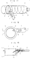
- a plastic bottle 20 is inserted to inside the covering member 1 and the blade 3 is pressed through the side wall 21 of the plastic bottle 20. While the grip part 2 is held, the plastic bottle 20 is then turned in the direction such that the edge 3a cuts into it.
- the cutting direction of the blade 3 at this time is set so that it intersects with a plane perpendicular to the center axis of the covering member 1, the plastic bottle 20 is cut in the form of a spiral.
- the blade 3 is inclined with respect to the inside-outside direction of the side wall 21 as it cuts the side wall 21 of the plastic bottle 20.
- the cut side wall 21 easily opens out along the sides of the blade 3 without applying a pressure to the blade 3.
- no strong frictional forces arise between the blade 3 and the side wall 21, a strong force is not necessary for cutting, and it is possible to cut the plastic bottle efficiently while rotating it relatively easily.
- the edge 3a abuts with the side wall 21 diagonally as it cuts, forces do not concentrate on a part of the edge 3a and there is relatively little wear of the edge 3a.
- a covering member 1 is cylindrical, and the upper end face 1a and the lower end face 1b thereof are formed substantially perpendicular with respect to the center axis of the covering member 1.
- a grip part 2 is attached to the outer side of the covering member 1 on an extension line of the upper end face 1a and in parallel with the upper end face 1a.
- a blade 3 is disposed projecting diagonally with respect to the center axis of the covering member 1, and an edge 3a of the blade 3 is provided in parallel with this projection direction.
- the plastic bottle cutting implement of this preferred embodiment is used in the same way as that of the first preferred embodiment and has a similar effect, but because the grip part 2 is parallel with the upper end face la of the covering member 1 it is easier to use.
- the upper end face 1a and the lower end face 1b of a covering member 1 are formed parallel with each other and inclined with respect to the center axis of the covering member 1.
- a grip part 2 is attached to the outer side of the covering member 1 on an extension line of the upper end face la and in parallel with the upper end face 1a.
- a blade 3 is disposed parallel with the grip part 2, i.e. projecting diagonally with respect to the center axis of the covering member 1.
- the plastic bottle cutting implement of this preferred embodiment is used in the same way as that of the first preferred embodiment described above and has a similar effect.
- the upper end face la and the lower end face 1b of a covering member 1 are formed substantially perpendicular to the center axis of the covering member 1.
- a grip part 2 is attached to the side wall of the covering member 1 at an incline with respect thereto so as to intersect diagonally with the imaginary center axis of the cylindrical covering member 1 and so that the outer end of the grip part 2 is positioned above the upper end face la of the covering member 1 in the drawing.
- a rectangular cutaway 4 is provided in a part of the side wall of the covering member 1 adjacent to the upper end face 1a.
- Plate-shaped receiving parts 5, 5 are formed projecting in parallel with each other from the outer side of the covering member 1, one at each side of the cutaway 4.
- a bar-shaped grip part 2 of a size such that it has slight looseness with respect to the receiving parts 5, 5 is fitted between the receiving parts 5, 5, and side walls of the grip part 2 are pivotally attached to the receiving parts 5, 5 by pins 6.
- the grip part 2 is hollow and a narrow and long through hole 7 is provided in the center of the face of the grip part 2 facing downward in the drawings and extending in the length direction of the grip part 2, and a screw member 8 is fitted in the through hole 7.
- a blade 3 is inserted in the hollow part of the grip part 2, a through hole is provided in the blade 3 near the end of the grip part 2 and the end of the screw member 8 is fitted into this through hole.
- the plastic bottle cutting implement of this preferred embodiment is used in the same way as those of the preferred embodiments described above and has the same effect. Also, when the plastic bottle cutting implement is not being used, it is possible to completely retract the blade 3 into the grip part 2 and fold the grip part 2 to inside the covering member 1 about the pins 6. As a result, the plastic bottle cutting implement takes up little storage space and is easy to carry around.
- a blade 9 of the plastic bottle cutting implement of this preferred embodiment is formed in an arcuate concave shape in the cross-blade direction. Also, as shown in Fig. 10, the blade 9 is disposed slightly inclined with respect to the upper end face 1a and the lower end face 1b of the covering member 1, and the direction of the side surfaces of the blade 9 leading to the blade edge 9a, i.e. the direction in which it cuts the plastic bottle, intersects with a plane perpendicular to the center axis of the covering member 1.
- the direction of projection of the blade 9 intersects with the center axis of the covering member 1 diagonally at an angle other than 90°.
- the blade edge 9a of the blade 9 is formed in a concave shape in the cross-blade direction.
- the upper end face 1a and the lower end face 1b of this covering member 1 are perpendicular to the center axis of the covering member 1.
- the plastic bottle cutting implement of this preferred embodiment is used in the same way as that of the preferred embodiments described above, and has the same effect. Also, because the cut line 22 made by this plastic bottle cutting implement is diagonal with respect to the center axis of the plastic bottle 20, as shown in Fig. 11, the side wall 21 of the plastic bottle is cut in a spiral and is reduced to a band. As a result, the implement is extremely easy to use, and the band-shaped cut plastic bottle side wall 21 can be made compact by being wound into a roll. Also, because the blade edge 9a of the blade 9 is formed in an arcuate concave shape, cutting is easy.
- a grip part 2 is attached to the outer side of the covering member 1 in parallel with the upper end face 1a.
- the grip part 2 is hollow and narrow and long through holes 7 are provided in the centers of the upper and lower faces of the grip part 2 and extending in the length direction of the grip part 2.
- a blade 9 is inserted into the hollow part of the grip part 2, a through hole is provided in the blade 9 in the vicinity of the front end of the grip part 2 and the end of a screw member 8 is fitted through this through hole.
- a square nut 11 is screwed onto the end of the screw member 8.
- the blade 9 is formed in an arcuate concave shape in the cross-blade direction, and is bent downward in the vicinity where it abuts with the inner side of the covering member 1.
- a space 25 for receiving the blade 9 is formed in the base end of the grip part 2 and connecting with the inner side of the covering member 1.
- the plastic bottle cutting implement of this preferred embodiment also has the same effect as those of the preferred embodiments described above.
- the screw member 8 When the screw member 8 is tightened the blade 9 becomes slidable in parallel with the grip part 2 and can be received in the space 25 in the base end part of the grip part 2.
- the plastic bottle cutting implement of this invention is not limited to the preferred embodiments described above, and the shapes and materials of the various parts can be suitably changed, and for example indentations may be provided in the grip part 2 where fingers grip it to make it easier to hold.
- the means for fixing the blade or cutter also may be suitably changed.
- the position and angle at which the blade is attached may also be set according to convenience.
- This invention with a simple construction, makes it possible to cut a plastic bottle easily and efficiently, and makes it possible to reduce a used plastic bottle to a compact form for disposal. Furthermore, there is little wearing of the blade and the life of the blade is long.
Landscapes
- Life Sciences & Earth Sciences (AREA)
- Forests & Forestry (AREA)
- Engineering & Computer Science (AREA)
- Mechanical Engineering (AREA)
- Knives (AREA)
- Details Of Rigid Or Semi-Rigid Containers (AREA)
Applications Claiming Priority (2)
| Application Number | Priority Date | Filing Date | Title |
|---|---|---|---|
| JP296348/95 | 1995-10-07 | ||
| JP29634895 | 1995-10-07 |
Publications (1)
| Publication Number | Publication Date |
|---|---|
| EP0769355A1 true EP0769355A1 (de) | 1997-04-23 |
Family
ID=17832396
Family Applications (1)
| Application Number | Title | Priority Date | Filing Date |
|---|---|---|---|
| EP96307308A Withdrawn EP0769355A1 (de) | 1995-10-07 | 1996-10-07 | Schneidgerät für Kunststoffflaschen |
Country Status (2)
| Country | Link |
|---|---|
| US (1) | US5740612A (de) |
| EP (1) | EP0769355A1 (de) |
Cited By (1)
| Publication number | Priority date | Publication date | Assignee | Title |
|---|---|---|---|---|
| USD957227S1 (en) | 2019-04-01 | 2022-07-12 | The Green Twist LLC | Cutting device |
Families Citing this family (14)
| Publication number | Priority date | Publication date | Assignee | Title |
|---|---|---|---|---|
| US6000262A (en) * | 1997-09-10 | 1999-12-14 | William C. Dries | Apparatus and method for producing open-topped cylindrical containers from closed-topped cylindrical containers |
| US6101720A (en) * | 1998-04-20 | 2000-08-15 | Jones; Benjamin C. | Special can opener |
| US6477775B2 (en) * | 2000-01-14 | 2002-11-12 | Dale Scribner | Device and methods for opening closed containers |
| US6935030B2 (en) | 2001-12-20 | 2005-08-30 | James Loik | Spiral cut craft tool |
| US20060048619A1 (en) * | 2004-09-08 | 2006-03-09 | Graham Packaging Company, L.P. | Four sided cutter with relief |
| US20070261526A1 (en) * | 2005-12-06 | 2007-11-15 | Cunningham Christopher H | Bagel Slicer |
| WO2007100581A2 (en) * | 2006-02-22 | 2007-09-07 | C. R. Bard, Inc. | Growth cuff removal devices and methods of use |
| GB0622398D0 (en) * | 2006-11-09 | 2006-12-20 | Carbonite Corp | Beverage containers |
| US20080190879A1 (en) * | 2007-02-14 | 2008-08-14 | Apothecary Innovations, Llc | Cutting device to disable a childproof container |
| US9566717B2 (en) * | 2013-01-22 | 2017-02-14 | 3M Innovative Properties Company | Apparatus for cutting electronic monitoring bracelet straps |
| US20180326234A1 (en) * | 2017-05-10 | 2018-11-15 | Ronald William Sable, JR. | Neck Tie Cutter |
| US10588449B2 (en) * | 2017-10-16 | 2020-03-17 | Steven Jay Self | Cutting device |
| US11220017B2 (en) * | 2018-08-01 | 2022-01-11 | The Green Twist LLC | Cutting device |
| US12005599B2 (en) * | 2020-11-09 | 2024-06-11 | Armando Zimbrón | Methods and systems for a waste management system |
Citations (5)
| Publication number | Priority date | Publication date | Assignee | Title |
|---|---|---|---|---|
| US3940842A (en) * | 1975-07-28 | 1976-03-02 | Perrinelle Alexandre G | Device for slitting wieners for barbecuing |
| US4333234A (en) * | 1980-09-17 | 1982-06-08 | Smith Dean C | Paper slitting device |
| EP0220850A2 (de) * | 1985-10-22 | 1987-05-06 | Hallen Company | Schneidegerät für Flaschenkapseln |
| EP0279737A2 (de) * | 1987-02-19 | 1988-08-24 | Virax S.A. | Schneidvorrichtung für Kunststoffrohre mit geführtem Messer |
| DE3812336C1 (de) * | 1988-04-14 | 1989-08-24 | Effem Gmbh, 2810 Verden, De |
Family Cites Families (8)
| Publication number | Priority date | Publication date | Assignee | Title |
|---|---|---|---|---|
| DE735641C (de) * | 1939-04-01 | 1943-05-20 | Metallgesellschaft Ag | Entmantelungswerkzeug |
| US3398610A (en) * | 1967-05-15 | 1968-08-27 | James J. Matthews | Insulation end removing tool |
| US3533313A (en) * | 1968-02-02 | 1970-10-13 | James J Matthews | Tool for stripping insulation |
| GB1240288A (en) * | 1968-10-03 | 1971-07-21 | Alfred George Smith | Egg topping device |
| US4532837A (en) * | 1982-09-13 | 1985-08-06 | Cushenbery Terry E | Nipple grooving device |
| US4503612A (en) * | 1983-08-08 | 1985-03-12 | Davis Raymond E | Safety guard equipped cardboard box cutter |
| JPH036155A (ja) * | 1989-06-01 | 1991-01-11 | Nec Corp | バッファ制御方式 |
| JP3006155U (ja) | 1994-07-05 | 1995-01-17 | 光永通商株式会社 | プラスチックボトルの切断器具 |
-
1996
- 1996-09-30 US US08/723,090 patent/US5740612A/en not_active Expired - Fee Related
- 1996-10-07 EP EP96307308A patent/EP0769355A1/de not_active Withdrawn
Patent Citations (5)
| Publication number | Priority date | Publication date | Assignee | Title |
|---|---|---|---|---|
| US3940842A (en) * | 1975-07-28 | 1976-03-02 | Perrinelle Alexandre G | Device for slitting wieners for barbecuing |
| US4333234A (en) * | 1980-09-17 | 1982-06-08 | Smith Dean C | Paper slitting device |
| EP0220850A2 (de) * | 1985-10-22 | 1987-05-06 | Hallen Company | Schneidegerät für Flaschenkapseln |
| EP0279737A2 (de) * | 1987-02-19 | 1988-08-24 | Virax S.A. | Schneidvorrichtung für Kunststoffrohre mit geführtem Messer |
| DE3812336C1 (de) * | 1988-04-14 | 1989-08-24 | Effem Gmbh, 2810 Verden, De |
Cited By (1)
| Publication number | Priority date | Publication date | Assignee | Title |
|---|---|---|---|---|
| USD957227S1 (en) | 2019-04-01 | 2022-07-12 | The Green Twist LLC | Cutting device |
Also Published As
| Publication number | Publication date |
|---|---|
| US5740612A (en) | 1998-04-21 |
Similar Documents
| Publication | Publication Date | Title |
|---|---|---|
| EP0769355A1 (de) | Schneidgerät für Kunststoffflaschen | |
| AU619145B2 (en) | Universal utility knife | |
| KR100377428B1 (ko) | 가위 | |
| US5542184A (en) | Tape measure knife attachment for cutting drywall | |
| EP0819503A2 (de) | Verriegelungsvorrichtung für aufklappbares Werkzeug | |
| US5467497A (en) | Adjustable drywall corner tool | |
| US5638603A (en) | Wrappage cutter | |
| US5490331A (en) | Utility knife for cutting and scraping | |
| KR920019458A (ko) | 드릴 및 그 체결을 위해 사용되는 로크 나사 | |
| KR101083621B1 (ko) | 상이한 반경을 지닌 코너부를 가지는 인덱서블 인서트 | |
| US6745476B2 (en) | Cutting tool | |
| US6006384A (en) | Drywall knife with screwdriver | |
| US20050072004A1 (en) | Opening assist mechanism for a folding knife | |
| US20020004985A1 (en) | Automatically retractable safety utility knife | |
| JP2002508716A (ja) | 手持ち式かんな削り機械 | |
| EP1333950B1 (de) | Schlüssel zum montieren und ausbauen eines schneideinsatzes | |
| US5864954A (en) | Slitter tool | |
| KR970014955A (ko) | 코너컷터 | |
| US6935030B2 (en) | Spiral cut craft tool | |
| US6722044B2 (en) | Sheet material cutting tool | |
| USD360149S (en) | Tool for drawing straight lines, measuring lengths, and cutting in straight lines with hand-held knife-like implements | |
| US20060053641A1 (en) | Pencil shaving device | |
| AU4449199A (en) | Folding combination tool for electricians | |
| KR200170804Y1 (ko) | 손톱깎이 | |
| CA2194635A1 (en) | Metal shears |
Legal Events
| Date | Code | Title | Description |
|---|---|---|---|
| PUAI | Public reference made under article 153(3) epc to a published international application that has entered the european phase |
Free format text: ORIGINAL CODE: 0009012 |
|
| AK | Designated contracting states |
Kind code of ref document: A1 Designated state(s): DE FR GB |
|
| 17P | Request for examination filed |
Effective date: 19971017 |
|
| STAA | Information on the status of an ep patent application or granted ep patent |
Free format text: STATUS: THE APPLICATION IS DEEMED TO BE WITHDRAWN |
|
| 18D | Application deemed to be withdrawn |
Effective date: 19990501 |