EP0769424A2 - Sous-ensemble comprenant un volant, un arbre de colonne de direction et un générateur de gaz - Google Patents
Sous-ensemble comprenant un volant, un arbre de colonne de direction et un générateur de gaz Download PDFInfo
- Publication number
- EP0769424A2 EP0769424A2 EP96115813A EP96115813A EP0769424A2 EP 0769424 A2 EP0769424 A2 EP 0769424A2 EP 96115813 A EP96115813 A EP 96115813A EP 96115813 A EP96115813 A EP 96115813A EP 0769424 A2 EP0769424 A2 EP 0769424A2
- Authority
- EP
- European Patent Office
- Prior art keywords
- gas generator
- steering wheel
- hub
- steering shaft
- steering
- Prior art date
- Legal status (The legal status is an assumption and is not a legal conclusion. Google has not performed a legal analysis and makes no representation as to the accuracy of the status listed.)
- Granted
Links
- 239000011324 bead Substances 0.000 claims description 3
- 230000000295 complement effect Effects 0.000 description 1
- 238000009434 installation Methods 0.000 description 1
- 238000004519 manufacturing process Methods 0.000 description 1
- 230000001681 protective effect Effects 0.000 description 1
- 230000007704 transition Effects 0.000 description 1
Images


Classifications
-
- B—PERFORMING OPERATIONS; TRANSPORTING
- B60—VEHICLES IN GENERAL
- B60R—VEHICLES, VEHICLE FITTINGS, OR VEHICLE PARTS, NOT OTHERWISE PROVIDED FOR
- B60R21/00—Arrangements or fittings on vehicles for protecting or preventing injuries to occupants or pedestrians in case of accidents or other traffic risks
- B60R21/02—Occupant safety arrangements or fittings, e.g. crash pads
- B60R21/16—Inflatable occupant restraints or confinements designed to inflate upon impact or impending impact, e.g. air bags
-
- B—PERFORMING OPERATIONS; TRANSPORTING
- B60—VEHICLES IN GENERAL
- B60R—VEHICLES, VEHICLE FITTINGS, OR VEHICLE PARTS, NOT OTHERWISE PROVIDED FOR
- B60R21/00—Arrangements or fittings on vehicles for protecting or preventing injuries to occupants or pedestrians in case of accidents or other traffic risks
- B60R21/02—Occupant safety arrangements or fittings, e.g. crash pads
- B60R21/16—Inflatable occupant restraints or confinements designed to inflate upon impact or impending impact, e.g. air bags
- B60R21/20—Arrangements for storing inflatable members in their non-use or deflated condition; Arrangement or mounting of air bag modules or components
- B60R21/203—Arrangements for storing inflatable members in their non-use or deflated condition; Arrangement or mounting of air bag modules or components in steering wheels or steering columns
- B60R21/2032—Arrangements for storing inflatable members in their non-use or deflated condition; Arrangement or mounting of air bag modules or components in steering wheels or steering columns the inflator or inflatable member not being rotatable with the steering wheel; Arrangements using the steering column or steering wheel rim for storing, supplying or evacuating the inflation gas or for storing the inflatable member
-
- B—PERFORMING OPERATIONS; TRANSPORTING
- B62—LAND VEHICLES FOR TRAVELLING OTHERWISE THAN ON RAILS
- B62D—MOTOR VEHICLES; TRAILERS
- B62D1/00—Steering controls, i.e. means for initiating a change of direction of the vehicle
- B62D1/02—Steering controls, i.e. means for initiating a change of direction of the vehicle vehicle-mounted
- B62D1/04—Hand wheels
- B62D1/10—Hubs; Connecting hubs to steering columns, e.g. adjustable
Definitions
- the invention relates to an assembly comprising a steering wheel, a steering shaft connected to it in a rotationally fixed manner and a gas generator for deploying an airbag arranged in the steering wheel.
- the gas generator usually arranged inside the steering wheel is ignited, if necessary, so that an airbag also arranged inside the steering wheel is inflated and provides a protective effect for the driver of a motor vehicle in the event of a frontal impact.
- the object of the invention is to reduce the weight of the steering wheel in an assembly of the type mentioned and to save the installation space for accommodating the gas generator in it.
- the steering shaft has a cavity extending along its longitudinal axis, which opens at least at the end of the steering shaft assigned to the steering wheel; that the steering wheel has a hub and in this an opening through which the cavity is in flow communication with the interior of the hub; that the gas generator is inserted into the cavity, which has an elongated housing; and that the gas generator is axially fixed in the cavity of the steering shaft.
- the gas generator inserted into the interior of the steering shaft can be fixed during assembly between a support surface on the steering shaft and an opposite clamping surface. Since the gas generator is no longer part of the steering wheel, this results in a lower weight and a smaller size.
- FIG. 1 a first embodiment of an assembly according to the invention is shown schematically.
- the steering wheel (not shown) contains a partially illustrated hub 10 which is provided with an opening 11 which connects the inside of the hub 10 to the outside.
- a sleeve-like extension 12 is formed concentrically around this opening and is provided with an external thread 14.
- the inside diameter of the extension 12 is larger than the inside diameter of the opening 11, so that an annular clamping surface 16 is formed on the inside of the extension at the transition between the extension 12 and the hub 10.
- the extension 12 has a conical receptacle 18.
- the hub 10 is rotatably connected to a steering shaft 20 which is rotatably mounted in a tubular casing 22.
- the steering shaft 20 is hollow and has a cavity 23 extending along its longitudinal axis.
- the annular end face of the steering shaft 20 at its end assigned to the steering wheel forms a support surface 24.
- a conical extension 26 is formed on the outer circumference of the steering shaft 20, which has an annular contact surface 28 on its side facing away from the steering wheel has, on which the collar of a union nut 30 rests, which is screwed onto the thread 14 and braces the steering shaft non-rotatably with the hub 10.
- a generally cylindrical gas generator 31 is inserted into the cavity of the steering shaft 20 and is provided with a collar 32 which projects radially beyond the outer circumference of the housing. This collar is clamped between the clamping surface 16 and the support surface 24, so that the gas generator is fixed in the axial direction of the steering shaft 20.
- the housing of the gas generator extends through the bore 11 into the interior of the hub 10, and in this area of the housing there are outflow openings 34 through which the gas generation charge (not shown) if necessary, generated gas can flow into the hub 10 of the steering wheel and unfold an airbag arranged there.
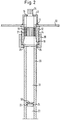
- FIG. 10 A further embodiment of the invention is shown in FIG. With regard to the components known from the previous embodiment, reference is made to the preceding explanations.
- the hub 10 and the extension 12 can also be seen in this embodiment.
- the extension In addition to the cone-like receptacle 18, the extension is provided with a spline profile 19 which is complementary to a spline profile 21 which is formed on the steering shaft 20.
- a cup-like holding part 40 is attached, which is provided with an opening concentric to the bore 11 in the hub 10 and on the inside of which, surrounding this bore, the clamping surface 16 is formed.
- the steering shaft 20 is hollow and, at a certain distance from its end assigned to the steering wheel, has on its inside a radially inwardly projecting bead 25 on which the support surface 24 is formed.
- the gas generator 30 is clamped between the clamping surface 16 and the support surface 24, two disc spring elements 50 being inserted between the end of the gas generator assigned to the support surface 24 and the support surface 24, which can compensate for manufacturing tolerances.
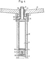
- FIG. 3 shows a further embodiment of the invention.
- the steering shaft has at its end assigned to the hub 10 an extension 60 projecting into the cavity 23, so that an annular shoulder is formed which forms the clamping surface 16.
- the gas generator 31 has an extension 62 which is tapered in diameter, so that Between the extension 62 and the housing of the gas generator 31, a likewise annular shoulder is formed, which rests on the clamping surface 16.
- the support surface 24 is formed by an abutment element 64 which is inserted into the cavity 23 of the steering shaft 20 and is braced axially by means of a screw 66.
- a plate spring element 50 is inserted between the support surface 24 and the gas generator.
- FIG. 4 shows a variant of the embodiment in FIG. 3.
- the gas generator ends in the steering shaft, and (with reference to the figure) above the gas generator 31, a separate tubular element 70 is inserted into the steering shaft 20, which is supported on the clamping surface 16 and extends into the interior of the hub 10.
- the outflow openings 34 at the end of the tubular element 70 arranged inside the hub 10, the inflow direction of the gas possibly generated by the gas generator 31 into an airbag arranged in the hub 10 can be influenced.
- the configuration of the assembly according to the invention results in the following advantages: since the gas generator is no longer arranged in the steering wheel itself, it has a lower weight and a smaller overall size.
- the gas generator is fixed in a particularly simple manner since it only has to be inserted into the interior of the steering shaft.
- the determination in the axial direction of the steering shaft takes place when the steering wheel is attached to the steering shaft, in which the gas generator is clamped between the support surface and the clamping surface.
- a union nut is preferably used to fasten the steering wheel to the steering shaft, which offers further advantages.
- this union nut is accessible from outside the hub, so that those to be arranged in the steering wheel hub Components of the gas bag restraint system can already be installed in the steering wheel before it is connected to the steering shaft.
Landscapes
- Engineering & Computer Science (AREA)
- Mechanical Engineering (AREA)
- Chemical & Material Sciences (AREA)
- Combustion & Propulsion (AREA)
- Transportation (AREA)
- Air Bags (AREA)
- Steering Controls (AREA)
Applications Claiming Priority (2)
| Application Number | Priority Date | Filing Date | Title |
|---|---|---|---|
| DE29516621U DE29516621U1 (de) | 1995-10-20 | 1995-10-20 | Baugruppe aus einem Lenkrad, einer Lenkwelle sowie einem Gasgenerator |
| DE29516621U | 1995-10-20 |
Publications (3)
| Publication Number | Publication Date |
|---|---|
| EP0769424A2 true EP0769424A2 (fr) | 1997-04-23 |
| EP0769424A3 EP0769424A3 (fr) | 1997-10-01 |
| EP0769424B1 EP0769424B1 (fr) | 2001-07-11 |
Family
ID=8014379
Family Applications (1)
| Application Number | Title | Priority Date | Filing Date |
|---|---|---|---|
| EP96115813A Expired - Lifetime EP0769424B1 (fr) | 1995-10-20 | 1996-10-02 | Sous-ensemble comprenant un volant, un arbre de colonne de direction et un générateur de gaz |
Country Status (8)
| Country | Link |
|---|---|
| US (1) | US5700031A (fr) |
| EP (1) | EP0769424B1 (fr) |
| JP (1) | JP2997651B2 (fr) |
| KR (1) | KR970020751A (fr) |
| CN (1) | CN1152513A (fr) |
| CZ (1) | CZ304196A3 (fr) |
| DE (2) | DE29516621U1 (fr) |
| ES (1) | ES2102338T1 (fr) |
Families Citing this family (9)
| Publication number | Priority date | Publication date | Assignee | Title |
|---|---|---|---|---|
| DE29516625U1 (de) * | 1995-10-20 | 1996-01-25 | Trw Occupant Restraint Systems Gmbh, 73551 Alfdorf | Lenkwelle für ein Fahrzeug mit einem Gassack-Rückhaltesystem |
| DE29606830U1 (de) * | 1996-04-15 | 1996-08-08 | Trw Occupant Restraint Systems Gmbh, 73551 Alfdorf | Baugruppe aus einem Lenkrad, einer Lenkwelle und einem Gassack-Modul |
| KR20000057618A (ko) | 1996-12-21 | 2000-09-25 | 볼프강 후텐로커 | 자동차용 스티어링 휠 장착형 구속 시스템 |
| DE59809761D1 (de) | 1997-04-16 | 2003-11-06 | Volkswagen Ag | Lenksäule für Insassenschutzeinrichtungen und Sicherheitslenkungen |
| DE19726260A1 (de) * | 1997-06-20 | 1998-12-24 | Temic Bayern Chem Airbag Gmbh | Gasgenerator für eine Sicherheitseinrichtung |
| US6227571B1 (en) * | 1999-11-03 | 2001-05-08 | Trw Vehicle Safety Systems Inc. | Telescoping vehicle steering column apparatus for helping to protect a vehicle driver |
| EP1211145B1 (fr) | 2000-11-25 | 2004-12-01 | Volkswagen Aktiengesellschaft | Coussin gonflable dans un volant pour un véhicule |
| US6989891B2 (en) * | 2001-11-08 | 2006-01-24 | Optiscan Biomedical Corporation | Device and method for in vitro determination of analyte concentrations within body fluids |
| DE202021106650U1 (de) | 2021-12-07 | 2023-03-08 | ZF Automotive Safety Germany GmbH | Lenkvorrichtung für ein Kraftfahrzeug |
Family Cites Families (12)
| Publication number | Priority date | Publication date | Assignee | Title |
|---|---|---|---|---|
| FR2098804A5 (fr) * | 1970-07-28 | 1972-03-10 | Peugeot & Renault | |
| DE2052357A1 (de) * | 1970-10-24 | 1972-04-27 | Lenkradwerk Gustav Petri Ag, 8750 Aschaffenburg | Lenkrad mit eingebautem Luftkissen |
| DE2143165A1 (de) * | 1971-08-28 | 1973-03-08 | Heckler & Koch Gmbh | Lenkrad fuer ein kraftfahrzeug o. dgl |
| FR2238614A1 (en) * | 1973-07-26 | 1975-02-21 | Eaton Corp | Safety airbag system for steering wheel - has gas distribution chamber fitted to top of steering column under special wheel with folded airbag |
| US5139281A (en) * | 1991-03-11 | 1992-08-18 | General Motors Corporation | Automotive steering column |
| US5342089A (en) * | 1993-01-13 | 1994-08-30 | Ideatech, Inc. | Combined air bag device and steering column for vehicles |
| FR2702724B1 (fr) * | 1993-03-18 | 1995-06-16 | Ecia Equip Composants Ind Auto | Ensemble de colonne de direction muni d'un module à sac gonflable, notamment pour véhicule automobile. |
| DE9407808U1 (de) * | 1994-05-11 | 1994-07-14 | Adam Opel AG, 65428 Rüsselsheim | Kraftfahrzeug |
| US5482315A (en) * | 1994-06-07 | 1996-01-09 | Morton International, Inc. | Large L/D ratio tubular hybrid gas generator for the inflation of air bags |
| JPH08156739A (ja) * | 1994-12-06 | 1996-06-18 | Sensor Technol Kk | エアバッグ装置を備えたステアリング装置 |
| DE19509165A1 (de) | 1995-03-14 | 1996-09-19 | Mst Automotive Gmbh | Gassack-Aufprallschutz-System |
| US5553888A (en) * | 1995-06-26 | 1996-09-10 | Alliedsignal Inc. | Snap-on, removable steering wheel with integral airbag housing |
-
1995
- 1995-10-20 DE DE29516621U patent/DE29516621U1/de not_active Expired - Lifetime
-
1996
- 1996-10-02 EP EP96115813A patent/EP0769424B1/fr not_active Expired - Lifetime
- 1996-10-02 DE DE59607263T patent/DE59607263D1/de not_active Expired - Fee Related
- 1996-10-02 ES ES96115813T patent/ES2102338T1/es active Pending
- 1996-10-15 US US08/729,946 patent/US5700031A/en not_active Expired - Fee Related
- 1996-10-17 CZ CZ963041A patent/CZ304196A3/cs unknown
- 1996-10-18 JP JP8276590A patent/JP2997651B2/ja not_active Expired - Lifetime
- 1996-10-18 KR KR1019960046643A patent/KR970020751A/ko not_active Abandoned
- 1996-10-18 CN CN96112781A patent/CN1152513A/zh active Pending
Also Published As
| Publication number | Publication date |
|---|---|
| DE59607263D1 (de) | 2001-08-16 |
| CN1152513A (zh) | 1997-06-25 |
| US5700031A (en) | 1997-12-23 |
| KR970020751A (ko) | 1997-05-28 |
| DE29516621U1 (de) | 1996-01-25 |
| EP0769424A3 (fr) | 1997-10-01 |
| JP2997651B2 (ja) | 2000-01-11 |
| EP0769424B1 (fr) | 2001-07-11 |
| JPH09123921A (ja) | 1997-05-13 |
| CZ304196A3 (en) | 1997-05-14 |
| ES2102338T1 (es) | 1997-08-01 |
Similar Documents
| Publication | Publication Date | Title |
|---|---|---|
| EP0700810B1 (fr) | Volant de véhicule avec système de retenue à sac gonflable intégré | |
| EP0691245B1 (fr) | Volant de véhicule pour l'implantation d'un système intégré de retenue par sac gonflable | |
| EP0607417B1 (fr) | Agencement prevenant la corrosion par contact dans des roues en magnesium | |
| DE19521937B4 (de) | Sicherheitsvorrichtung | |
| DE9408908U1 (de) | Gassack-Schutzvorrichtung | |
| DE19581552B4 (de) | Lenkrad mit vormontiertem Airbagmodul | |
| EP0802089A1 (fr) | Assemblage d'un volant, d'un arbre de direction et d'un module de coussin gonflable | |
| EP0769443A2 (fr) | Fixation entre le volant de direction d'un véhicule automobile et la colonne de direction | |
| EP0769424B1 (fr) | Sous-ensemble comprenant un volant, un arbre de colonne de direction et un générateur de gaz | |
| EP0769441A2 (fr) | Fixation d'un volant de direction de véhicule automobile sur un arbre de direction | |
| EP0779186B1 (fr) | Volant avec système de retenue pour occupant | |
| DE102017109209A1 (de) | Anzünderträger, baugruppe, gasgenerator sowie verfahren zur herstellung eines gasgenerators | |
| EP1007395A1 (fr) | Ensemble coussin gonflable présentant un boítier de guidage de gaz comportant des zones partielles d'evacuation | |
| EP0832791B1 (fr) | Module de sac gonflable pour système de retenue des passagers d'un véhicule | |
| DE8619591U1 (de) | Gaskissen-Aufprallschutzvorrichtung für Kraftfahrzeuge | |
| DE29613269U1 (de) | Gassack-Modul für ein Fahrzeuginsassen-Rückhaltesystem | |
| DE3527581A1 (de) | Kraftfahrzeug-lenkrad | |
| EP1410971B1 (fr) | Colonne de direction | |
| DE3110807C2 (de) | Einrichtung zur elektrischen Verbindung zwischen wenigstens zwei auf der Lenkradachse eines Kraftfahrzeuges befindlichen, gegeneinander drehbaren Bauteilen | |
| EP0769423A1 (fr) | Colonne de direction pour un véhicule comportant un système de retenue par sac gonflable | |
| EP1012024B1 (fr) | Volant de direction en deux parties | |
| DE19548266A1 (de) | Gasgenerator für ein Airbagsystem | |
| DE19749173C2 (de) | Kombinierte Klebe- und Formschlußverbindung zweier Bauteile | |
| DE10344904B4 (de) | Verbindungsanordnung an einem Kraftfahrzeug zwischen einem Airbagmodul eines Fahrerairbags und einer Lenkradnabe | |
| DE29705753U1 (de) | Anordnung zur Verbindung eines Gassacks mit einem Gasgenerator in einem Airbagmodul |
Legal Events
| Date | Code | Title | Description |
|---|---|---|---|
| PUAI | Public reference made under article 153(3) epc to a published international application that has entered the european phase |
Free format text: ORIGINAL CODE: 0009012 |
|
| AK | Designated contracting states |
Kind code of ref document: A2 Designated state(s): DE ES FR GB IT SE |
|
| ITCL | It: translation for ep claims filed |
Representative=s name: DR. ING. A. RACHELI & C. |
|
| GBC | Gb: translation of claims filed (gb section 78(7)/1977) | ||
| EL | Fr: translation of claims filed | ||
| REG | Reference to a national code |
Ref country code: ES Ref legal event code: BA2A Ref document number: 2102338 Country of ref document: ES Kind code of ref document: T1 |
|
| PUAL | Search report despatched |
Free format text: ORIGINAL CODE: 0009013 |
|
| AK | Designated contracting states |
Kind code of ref document: A3 Designated state(s): DE ES FR GB IT SE |
|
| 17P | Request for examination filed |
Effective date: 19971222 |
|
| RAP1 | Party data changed (applicant data changed or rights of an application transferred) |
Owner name: TRW OCCUPANT RESTRAINT SYSTEMS GMBH & CO. KG |
|
| 17Q | First examination report despatched |
Effective date: 19991025 |
|
| GRAG | Despatch of communication of intention to grant |
Free format text: ORIGINAL CODE: EPIDOS AGRA |
|
| GRAG | Despatch of communication of intention to grant |
Free format text: ORIGINAL CODE: EPIDOS AGRA |
|
| GRAH | Despatch of communication of intention to grant a patent |
Free format text: ORIGINAL CODE: EPIDOS IGRA |
|
| GRAH | Despatch of communication of intention to grant a patent |
Free format text: ORIGINAL CODE: EPIDOS IGRA |
|
| GRAA | (expected) grant |
Free format text: ORIGINAL CODE: 0009210 |
|
| AK | Designated contracting states |
Kind code of ref document: B1 Designated state(s): DE ES FR GB IT SE |
|
| PG25 | Lapsed in a contracting state [announced via postgrant information from national office to epo] |
Ref country code: IT Free format text: LAPSE BECAUSE OF FAILURE TO SUBMIT A TRANSLATION OF THE DESCRIPTION OR TO PAY THE FEE WITHIN THE PRE;WARNING: LAPSES OF ITALIAN PATENTS WITH EFFECTIVE DATE BEFORE 2007 MAY HAVE OCCURRED AT ANY TIME BEFORE 2007. THE CORRECT EFFECTIVE DATE MAY BE DIFFERENT FROM THE ONE RECORDED.SCRIBED TIME-LIMIT Effective date: 20010711 Ref country code: GB Free format text: LAPSE BECAUSE OF FAILURE TO SUBMIT A TRANSLATION OF THE DESCRIPTION OR TO PAY THE FEE WITHIN THE PRESCRIBED TIME-LIMIT Effective date: 20010711 Ref country code: FR Free format text: LAPSE BECAUSE OF FAILURE TO SUBMIT A TRANSLATION OF THE DESCRIPTION OR TO PAY THE FEE WITHIN THE PRESCRIBED TIME-LIMIT Effective date: 20010711 |
|
| REF | Corresponds to: |
Ref document number: 59607263 Country of ref document: DE Date of ref document: 20010816 |
|
| PG25 | Lapsed in a contracting state [announced via postgrant information from national office to epo] |
Ref country code: SE Free format text: LAPSE BECAUSE OF FAILURE TO SUBMIT A TRANSLATION OF THE DESCRIPTION OR TO PAY THE FEE WITHIN THE PRESCRIBED TIME-LIMIT Effective date: 20011011 |
|
| EN | Fr: translation not filed | ||
| GBV | Gb: ep patent (uk) treated as always having been void in accordance with gb section 77(7)/1977 [no translation filed] |
Effective date: 20010711 |
|
| PG25 | Lapsed in a contracting state [announced via postgrant information from national office to epo] |
Ref country code: ES Free format text: LAPSE BECAUSE OF FAILURE TO SUBMIT A TRANSLATION OF THE DESCRIPTION OR TO PAY THE FEE WITHIN THE PRESCRIBED TIME-LIMIT Effective date: 20020131 |
|
| PLBE | No opposition filed within time limit |
Free format text: ORIGINAL CODE: 0009261 |
|
| STAA | Information on the status of an ep patent application or granted ep patent |
Free format text: STATUS: NO OPPOSITION FILED WITHIN TIME LIMIT |
|
| 26N | No opposition filed | ||
| PGFP | Annual fee paid to national office [announced via postgrant information from national office to epo] |
Ref country code: DE Payment date: 20021031 Year of fee payment: 7 |
|
| PG25 | Lapsed in a contracting state [announced via postgrant information from national office to epo] |
Ref country code: DE Free format text: LAPSE BECAUSE OF NON-PAYMENT OF DUE FEES Effective date: 20040501 |