EP0769437A2 - Bremsflüssigkeitsdruck-Steuereinheit - Google Patents
Bremsflüssigkeitsdruck-Steuereinheit Download PDFInfo
- Publication number
- EP0769437A2 EP0769437A2 EP96120624A EP96120624A EP0769437A2 EP 0769437 A2 EP0769437 A2 EP 0769437A2 EP 96120624 A EP96120624 A EP 96120624A EP 96120624 A EP96120624 A EP 96120624A EP 0769437 A2 EP0769437 A2 EP 0769437A2
- Authority
- EP
- European Patent Office
- Prior art keywords
- control unit
- motor
- fluid pressure
- brake fluid
- electronic control
- Prior art date
- Legal status (The legal status is an assumption and is not a legal conclusion. Google has not performed a legal analysis and makes no representation as to the accuracy of the status listed.)
- Withdrawn
Links
- 239000012530 fluid Substances 0.000 title claims abstract description 28
- 239000004020 conductor Substances 0.000 claims 1
- 239000000463 material Substances 0.000 description 5
- 230000004907 flux Effects 0.000 description 4
- 239000011796 hollow space material Substances 0.000 description 2
Images

Classifications
-
- B—PERFORMING OPERATIONS; TRANSPORTING
- B60—VEHICLES IN GENERAL
- B60T—VEHICLE BRAKE CONTROL SYSTEMS OR PARTS THEREOF; BRAKE CONTROL SYSTEMS OR PARTS THEREOF, IN GENERAL; ARRANGEMENT OF BRAKING ELEMENTS ON VEHICLES IN GENERAL; PORTABLE DEVICES FOR PREVENTING UNWANTED MOVEMENT OF VEHICLES; VEHICLE MODIFICATIONS TO FACILITATE COOLING OF BRAKES
- B60T15/00—Construction arrangement, or operation of valves incorporated in power brake systems and not covered by groups B60T11/00 or B60T13/00
- B60T15/02—Application and release valves
-
- B—PERFORMING OPERATIONS; TRANSPORTING
- B60—VEHICLES IN GENERAL
- B60T—VEHICLE BRAKE CONTROL SYSTEMS OR PARTS THEREOF; BRAKE CONTROL SYSTEMS OR PARTS THEREOF, IN GENERAL; ARRANGEMENT OF BRAKING ELEMENTS ON VEHICLES IN GENERAL; PORTABLE DEVICES FOR PREVENTING UNWANTED MOVEMENT OF VEHICLES; VEHICLE MODIFICATIONS TO FACILITATE COOLING OF BRAKES
- B60T8/00—Arrangements for adjusting wheel-braking force to meet varying vehicular or ground-surface conditions, e.g. limiting or varying distribution of braking force
- B60T8/32—Arrangements for adjusting wheel-braking force to meet varying vehicular or ground-surface conditions, e.g. limiting or varying distribution of braking force responsive to a speed condition, e.g. acceleration or deceleration
- B60T8/34—Arrangements for adjusting wheel-braking force to meet varying vehicular or ground-surface conditions, e.g. limiting or varying distribution of braking force responsive to a speed condition, e.g. acceleration or deceleration having a fluid pressure regulator responsive to a speed condition
- B60T8/36—Arrangements for adjusting wheel-braking force to meet varying vehicular or ground-surface conditions, e.g. limiting or varying distribution of braking force responsive to a speed condition, e.g. acceleration or deceleration having a fluid pressure regulator responsive to a speed condition including a pilot valve responding to an electromagnetic force
- B60T8/3615—Electromagnetic valves specially adapted for anti-lock brake and traction control systems
- B60T8/3675—Electromagnetic valves specially adapted for anti-lock brake and traction control systems integrated in modulator units
- B60T8/368—Electromagnetic valves specially adapted for anti-lock brake and traction control systems integrated in modulator units combined with other mechanical components, e.g. pump units, master cylinders
Definitions
- the present invention relates to a brake fluid pressure control unit for controlling the brake fluid pressure in the wheel cylinders in response to commands from an electronic control unit, thereby preventing wheel locking.
- Such a brake fluid pressure control unit is used to add the antilock or traction control function to a vehicle brake device. It comprises a fluid pressure pump, an electric motor for driving the pump, and solenoid valves for opening and closing the fluid passages between the master cylinder and the wheel cylinders and the discharge passages leading from the wheel cylinders.
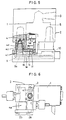
- FIG. 6 shows one of such control units that is disclosed in US Patent No. 4953918.
- a circuit block 2 is mounted to the front part of a motor 1.
- This block houses a hydraulic pump 3 (generally a plunger pump) driven by the motor 1 and fluid passages opened and closed by solenoid valves 4a.
- a hydraulic pump 3 generally a plunger pump driven by the motor 1 and fluid passages opened and closed by solenoid valves 4a.
- a conventional brake fluid pressure control unit has its circuit block 2, which comprises a pump unit 2a and a pressure adjusting unit 2b, disposed in front of the motor 1 and its solenoid valves 4a attached to the pressure adjusting unit 2b so as to extend in a direction perpendicular to the motor.
- SAE PAPER 920647 is disclosed a control unit having its solenoid valves disposed in parallel around the outer periphery of the motor to reduce its overall size. But this arrangement also requires two separate cases, one for the motor and the other for the solenoid valves. Thus, the overall size of the unit is large and the cost high.
- An object of the present invention is to provide a brake fluid pressure control unit which is small in size and inexpensive.
- Another object is to provide a brake fluid pressure control unit which can be easily coupled to an electronic control unit (from which driving signals are given to the fluid pressure control unit) which heretofore had to be mounted on a vehicle separately from the former.
- the pump unit of the circuit block is mounted on one axial end of the motor and the pressure adjusting means is provided to surround the outer periphery of the motor.
- the solenoid valves are provided parallel to the motor shaft.
- the motor is provided with a case having a portion thereof made of a magnetizable material. This portion forms a part of a magnetic circuit through which magnetic fluxes produced in the coil of the solenoid valves pass.
- the motor has a rear cover having a portion protruding outwards from the outer periphery of the motor.
- the solenoid valves are supported on the protruding portion of the rear cover.
- the rear cover is made of a magnetizable material so as to use it as a part of the magnetic circuit of the solenoid valves. Further the body case of the motor, which forms a part of the magnetic circuit of the motor, is also used as a part of the magnetic circuit of the solenoid valves.
- the rear cover of the motor has a housing in which is housed an electronic control unit having a microcomputer. Lead wires from the solenoid valves and the motor are guided into the housing and electrically connected to a control circuit in the electronic control unit.
- the control unit of the present invention is small in size because its pressure adjusting means (2b in Fig. 2) including solenoid valves is disposed around the outer periphery of the motor.
- the solenoid valves are supported on the rear cover of the motor.
- the rear cover and the body cover of the motor are also used as a part of the magnetic circuit of the motor and that of the solenoid valves. This serves to reduce the number of parts and the cost and weight of the entire unit.
- the space for fluid pressure control unit can be utilized efficiently and the entire length of wiring from the solenoid valves and the motor to the electronic control unit can be reduced to a minimum. This leads to a further reduction in size, weight and cost.
- the fluid pressure control unit and the electronic control unit can be integrated into a one-piece unit before shipping. This greatly facilitates handling. Also, such a one-piece unit can be mounted on a car much more easily. This serves to reduce the size, weight and cost of the entire brake system.
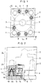
- Figs. 1-5 show a preferred embodiment of the brake fluid pressure control unit according to the present invention.
- a motor 1 is fitted in a recess 5 formed in a circuit block 2 with part of its body case 1a and part of its rear cover 1b protruding from the circuit block 2.
- a pressure adjusting unit 2b including pressure adjusting means 4 and a pump unit 2a.
- the positional relation between the units 2a and 2b are opposite to the conventional arrangement, with the unit 2b surrounding the outer periphery of the motor 1.
- the pressure adjusting means 4 are provided at a radial outer position of the rotor (1d) of the motor 1 and include a flow control valve. Since such a valve is disclosed in US Patent No. 4915459, it is deemed not necessary to describe it in detail.
- Solenoid valves 4a are secured to the rear face of the pressure adjusting unit 2b at its four corners so as to be parallel to the motor 1.
- the motor rear cover 1b is secured to the circuit block 2 by means of bolts 6 so as to protrude outwardly from the body case 1a to support coils 4e of the solenoid valves 4a thereon.
- the solenoid valves 4a are urged by the brake fluid pressure in such a direction as to get out of the circuit block 2.
- the force urging the valves 4a is borne by the rear cover 1b.
- Each solenoid valve has a stator 4b and a yoke 4d that are integral with the coil 4e.
- the body case 1a made of a magnetizable material, serves as a magnetic circuit. Namely, the magnetic flux produced in the coil of the motor 1 flows into the body case 1a.
- the magnetic flux produced in the coils 4e of each solenoid valve 4a flows through the stator 4b, armature 4c, yoke 4d and rear cover 1b. In other words, these parts act as a magnetic circuit.
- the motor body case 1a is reinforced by the circuit block 2, so that the former can be formed of a thin and low-strength material. This leads to a reduction in weight of the entire unit.
- the motor body case 1a may be used as part of the magnetic circuit of each solenoid valve coil 4e shown by arrow.
- the yokes (4d of Fig. 2) provided around each coil can be omitted, so that the number of parts and the overall weight can be reduced still further.
- the circuit block 2 may be formed of a magnetizable material so as to use it as the body case 1a of the motor. As shown in Fig. 4, the circuit block 2 serves as a common magnetic circuit member for all the solenoid valves 4a.
- Fig. 5 shows an embodiment in which an electronic control unit 9 is mounted in the motor rear cover 1b.
- the rear cover 1b has a hollow space 10 in which is mounted the electronic control unit 9, which comprises a circuit board 9a and a microcomputer (not shown).
- the solenoid valves 4a are kept in position by the rear cover 1b against the brake fluid pressure acting thereon. Also, lead pins 4f coupled to both ends of the coil 4e are inserted into the hollow space 10 through holes formed in the cover 1b and electrically connected to an electrical circuit on the circuit board 9a.
- Another lead pin 1f which extends from a brush base 1e coupled to a brush 1c of the motor 1, is electrically connected to a corresponding circuit on the circuit board 9a in the same manner as with the lead pins 4f.
- the pressure adjusting means 4 may not include a flow control valve as disclosed in US Patent 4915459 but may consist of a solenoid valve only as shown in US Patent 3617098.
- the rear cover 1b of the motor also serves as a housing for the electronic control unit, the fluid pressure control unit and the electronic control unit can be easily housed in a single unit. This will save space and simplify the wiring.
- this control unit has input ports 7 communicating with the master cylinder and output ports 8 leading to the wheel cylinders.
- the solenoid valves 4a serve to open and close the discharge circuits between the wheel cylinders and a low-pressure reservoir connected to the intake ports of pumps 3.
Landscapes
- Physics & Mathematics (AREA)
- Engineering & Computer Science (AREA)
- Electromagnetism (AREA)
- Transportation (AREA)
- Mechanical Engineering (AREA)
- Fluid Mechanics (AREA)
- Regulating Braking Force (AREA)
- Valves And Accessory Devices For Braking Systems (AREA)
- Braking Arrangements (AREA)
Applications Claiming Priority (5)
| Application Number | Priority Date | Filing Date | Title |
|---|---|---|---|
| JP228815/92 | 1992-08-27 | ||
| JP22881592 | 1992-08-27 | ||
| JP175219/93 | 1993-07-15 | ||
| JP5175219A JPH06122362A (ja) | 1992-08-27 | 1993-07-15 | ブレーキ液圧制御ユニット |
| EP93113047A EP0584682B1 (de) | 1992-08-27 | 1993-08-14 | Bremsflüssigkeitsdruck-Steuereinheit |
Related Parent Applications (2)
| Application Number | Title | Priority Date | Filing Date |
|---|---|---|---|
| EP93113047.0 Division | 1993-08-14 | ||
| EP93113047A Division EP0584682B1 (de) | 1992-08-27 | 1993-08-14 | Bremsflüssigkeitsdruck-Steuereinheit |
Publications (2)
| Publication Number | Publication Date |
|---|---|
| EP0769437A2 true EP0769437A2 (de) | 1997-04-23 |
| EP0769437A3 EP0769437A3 (de) | 1997-05-02 |
Family
ID=26496552
Family Applications (2)
| Application Number | Title | Priority Date | Filing Date |
|---|---|---|---|
| EP96120624A Withdrawn EP0769437A3 (de) | 1992-08-27 | 1993-08-14 | Bremsflüssigkeitsdruck-Steuereinheit |
| EP93113047A Expired - Lifetime EP0584682B1 (de) | 1992-08-27 | 1993-08-14 | Bremsflüssigkeitsdruck-Steuereinheit |
Family Applications After (1)
| Application Number | Title | Priority Date | Filing Date |
|---|---|---|---|
| EP93113047A Expired - Lifetime EP0584682B1 (de) | 1992-08-27 | 1993-08-14 | Bremsflüssigkeitsdruck-Steuereinheit |
Country Status (5)
| Country | Link |
|---|---|
| US (1) | US5362137A (de) |
| EP (2) | EP0769437A3 (de) |
| JP (1) | JPH06122362A (de) |
| KR (1) | KR0136846B1 (de) |
| DE (1) | DE69312404T2 (de) |
Cited By (2)
| Publication number | Priority date | Publication date | Assignee | Title |
|---|---|---|---|---|
| FR2865983A1 (fr) * | 2004-02-10 | 2005-08-12 | Siemens Vdo Automotive | Groupe electro-hydraulique, en particulier pour dispositif d'antiblocage de roues pour vehicule automobile |
| FR2901758A1 (fr) * | 2006-06-02 | 2007-12-07 | Siemens Vdo Automotive Sas | Groupe electro-hydraulique pour systeme de controle du freinage des roues d'un vehicule automobile |
Families Citing this family (13)
| Publication number | Priority date | Publication date | Assignee | Title |
|---|---|---|---|---|
| DE69123479T2 (de) * | 1990-03-30 | 1997-07-03 | Akebono Brake Ind | Bremssteuereinheit |
| EP0636525B1 (de) * | 1993-07-29 | 2000-06-14 | Sumitomo Wiring Systems, Ltd. | Steckverbindung |
| DE59300165D1 (de) * | 1993-09-08 | 1995-06-08 | Siemens Ag | Motor-Pumpen-Aggregat, insbesondere Kraftfahrzeug-Antiblockier-Bremsvorrichtung. |
| DE4422491A1 (de) * | 1994-06-28 | 1996-01-04 | Teves Gmbh Alfred | Druckregelvorrichtung |
| JPH08295221A (ja) * | 1995-02-27 | 1996-11-12 | Sumitomo Electric Ind Ltd | ブレーキ液圧制御装置 |
| DE19512804C2 (de) * | 1995-04-05 | 2000-06-15 | Lucas Ind Plc | Hydraulikaggregat für eine blockiergeschützte Fahrzeugbremsanlage |
| JPH09254758A (ja) * | 1996-03-21 | 1997-09-30 | Aisin Seiki Co Ltd | 車両用制動力制御装置 |
| DE19716187A1 (de) * | 1997-04-18 | 1998-10-29 | Itt Mfg Enterprises Inc | Motorgetriebenes Aggregat |
| US6739881B2 (en) | 2001-05-31 | 2004-05-25 | Trw Inc. | High integration electronic assembly and method |
| JP4595395B2 (ja) * | 2003-09-26 | 2010-12-08 | 株式会社アドヴィックス | 車両用ブレーキ液圧制御用アクチュエータ及びその検査装置並びに検査方法 |
| DE202007012652U1 (de) * | 2007-09-10 | 2007-11-22 | Bürkert Werke GmbH & Co. KG | Magnetventil |
| CN110944885B (zh) * | 2017-07-20 | 2022-03-08 | 克诺尔轨道车辆系统有限公司 | 节省空间的制动控制单元 |
| JP7444023B2 (ja) | 2020-10-30 | 2024-03-06 | 株式会社アドヴィックス | 車両用制動装置 |
Citations (1)
| Publication number | Priority date | Publication date | Assignee | Title |
|---|---|---|---|---|
| US4953918A (en) | 1988-09-03 | 1990-09-04 | Sumitomo Electric Industries Ltd. | Modulator for use in an anti-lock brake control system |
Family Cites Families (11)
| Publication number | Priority date | Publication date | Assignee | Title |
|---|---|---|---|---|
| SE392435B (sv) * | 1975-02-19 | 1977-03-28 | Blomberg Folke Ivar | Lasningsforhindrande aggregat for inbyggnad i en hydraulfluidkrets |
| JPS5720829Y2 (de) * | 1978-04-28 | 1982-05-06 | ||
| EP0095489A1 (de) * | 1981-12-04 | 1983-12-07 | Garlock Inc. | Antiblockierbremsmodulator, vorrichtung und verfahren |
| GB2225168A (en) * | 1988-10-28 | 1990-05-23 | Akebono Brake Ind | Electromagnetic valve device |
| US5022717A (en) * | 1988-12-12 | 1991-06-11 | Lucas Industries Public Limited Company | Pressure control unit, especially for motor vehicle brake systems |
| DE69123479T2 (de) * | 1990-03-30 | 1997-07-03 | Akebono Brake Ind | Bremssteuereinheit |
| DE4013159A1 (de) * | 1990-04-25 | 1991-10-31 | Bosch Gmbh Robert | Gehaeuseblock fuer ein hydraulisches bremssystem |
| DE4013160A1 (de) * | 1990-04-25 | 1991-10-31 | Bosch Gmbh Robert | Gehaeuseblock fuer ein hydraulisches bremssystem |
| FR2675446A1 (fr) * | 1991-04-17 | 1992-10-23 | Bendix Europ Service Tech | Dispositif hydraulique de freinage. |
| DE4120665A1 (de) * | 1991-06-22 | 1992-12-24 | Teves Gmbh Alfred | Elektromotorisch angetriebene hydraulikpumpe |
| JPH05208672A (ja) * | 1992-01-31 | 1993-08-20 | Sumitomo Electric Ind Ltd | ブレーキ液圧制御装置 |
-
1993
- 1993-07-15 JP JP5175219A patent/JPH06122362A/ja active Pending
- 1993-08-14 EP EP96120624A patent/EP0769437A3/de not_active Withdrawn
- 1993-08-14 DE DE69312404T patent/DE69312404T2/de not_active Expired - Fee Related
- 1993-08-14 EP EP93113047A patent/EP0584682B1/de not_active Expired - Lifetime
- 1993-08-18 KR KR1019930015998A patent/KR0136846B1/ko not_active Expired - Fee Related
- 1993-08-26 US US08/111,787 patent/US5362137A/en not_active Expired - Fee Related
Patent Citations (1)
| Publication number | Priority date | Publication date | Assignee | Title |
|---|---|---|---|---|
| US4953918A (en) | 1988-09-03 | 1990-09-04 | Sumitomo Electric Industries Ltd. | Modulator for use in an anti-lock brake control system |
Cited By (4)
| Publication number | Priority date | Publication date | Assignee | Title |
|---|---|---|---|---|
| FR2865983A1 (fr) * | 2004-02-10 | 2005-08-12 | Siemens Vdo Automotive | Groupe electro-hydraulique, en particulier pour dispositif d'antiblocage de roues pour vehicule automobile |
| WO2005087564A1 (fr) * | 2004-02-10 | 2005-09-22 | Siemens Vdo Automotive | Groupe electro-hydraulique, en particulier pour dispositif d’antiblocage de roues pour vehicule automobile |
| US7368826B2 (en) | 2004-02-10 | 2008-05-06 | Siemens Vdo Automotive | Electro-hydraulic unit, in particular for anti-lock devices for automotive vehicle wheels |
| FR2901758A1 (fr) * | 2006-06-02 | 2007-12-07 | Siemens Vdo Automotive Sas | Groupe electro-hydraulique pour systeme de controle du freinage des roues d'un vehicule automobile |
Also Published As
| Publication number | Publication date |
|---|---|
| JPH06122362A (ja) | 1994-05-06 |
| EP0584682A3 (de) | 1994-11-02 |
| DE69312404D1 (de) | 1997-09-04 |
| DE69312404T2 (de) | 1998-03-05 |
| EP0584682B1 (de) | 1997-07-23 |
| EP0584682A2 (de) | 1994-03-02 |
| KR0136846B1 (ko) | 1998-05-15 |
| US5362137A (en) | 1994-11-08 |
| EP0769437A3 (de) | 1997-05-02 |
| KR940003801A (ko) | 1994-03-12 |
Similar Documents
| Publication | Publication Date | Title |
|---|---|---|
| US5362137A (en) | Brake fluid pressure control unit | |
| US5688028A (en) | Brake pressure controller | |
| JP3031977B2 (ja) | 電気的な接続装置 | |
| US8159098B2 (en) | Motor control apparatus, power steering apparatus and brake control apparatus | |
| US8038423B2 (en) | Electric pump with relief valve | |
| JP3437265B2 (ja) | パイロット形電磁弁の給電装置 | |
| US5482362A (en) | Anti-lock brake control valve control module | |
| US6241489B1 (en) | Internal electrical connector for a hydraulic control unit | |
| EP3337015B1 (de) | Motor und bremsvorrichtung damit | |
| CN110944888B (zh) | 液压控制装置 | |
| US6224169B1 (en) | Integrated brake fluid control electrical connection apparatus | |
| JP5353621B2 (ja) | 車両用ブレーキ液圧制御装置 | |
| US6616249B2 (en) | Device for mounting coil assemblies of solenoid valves in electronically controlled brake systems | |
| CN105818794A (zh) | 线圈组件 | |
| JPH09193788A (ja) | ブレーキ圧力制御装置 | |
| US6616248B2 (en) | Automotive anti-lock brake control system | |
| US6247435B1 (en) | Arrangement for providing electrical connections with an engine control unit | |
| EP0625661B1 (de) | Druckregelvorrichtung | |
| US5755494A (en) | Brake control module | |
| JP3754569B2 (ja) | 車両用ブレーキ液圧制御装置 | |
| JP4741446B2 (ja) | 車載用のブレーキ液圧制御装置 | |
| US7368826B2 (en) | Electro-hydraulic unit, in particular for anti-lock devices for automotive vehicle wheels | |
| JP2004001684A (ja) | 電子的に調整される電気−空気圧制動装置の電磁調整弁を備えかつcanデータバスを介して制御されるたebs車輪変調器制御装置用の電磁石コイルー圧力センサ装置 | |
| KR20200010267A (ko) | 전기 모터를 구비한 차량 브레이크 시스템의 슬립 제어의 유압 유닛 | |
| JPH0719365A (ja) | 電磁制御弁の組立構造 |
Legal Events
| Date | Code | Title | Description |
|---|---|---|---|
| PUAI | Public reference made under article 153(3) epc to a published international application that has entered the european phase |
Free format text: ORIGINAL CODE: 0009012 |
|
| PUAL | Search report despatched |
Free format text: ORIGINAL CODE: 0009013 |
|
| AC | Divisional application: reference to earlier application |
Ref document number: 584682 Country of ref document: EP |
|
| AK | Designated contracting states |
Kind code of ref document: A2 Designated state(s): DE FR GB |
|
| AK | Designated contracting states |
Kind code of ref document: A3 Designated state(s): DE FR GB |
|
| 17P | Request for examination filed |
Effective date: 19970416 |
|
| RAP1 | Party data changed (applicant data changed or rights of an application transferred) |
Owner name: SUMITOMO ELECTRIC INDUSTRIES, LTD. |
|
| 17Q | First examination report despatched |
Effective date: 19981217 |
|
| STAA | Information on the status of an ep patent application or granted ep patent |
Free format text: STATUS: THE APPLICATION IS DEEMED TO BE WITHDRAWN |
|
| 18D | Application deemed to be withdrawn |
Effective date: 19990428 |