EP0769683A2 - Système de surveillance d'un niveau prédéterminé d'un fluide dans un récipient - Google Patents
Système de surveillance d'un niveau prédéterminé d'un fluide dans un récipient Download PDFInfo
- Publication number
- EP0769683A2 EP0769683A2 EP96116314A EP96116314A EP0769683A2 EP 0769683 A2 EP0769683 A2 EP 0769683A2 EP 96116314 A EP96116314 A EP 96116314A EP 96116314 A EP96116314 A EP 96116314A EP 0769683 A2 EP0769683 A2 EP 0769683A2
- Authority
- EP
- European Patent Office
- Prior art keywords
- adapter
- container wall
- arrangement according
- container
- attached
- Prior art date
- Legal status (The legal status is an assumption and is not a legal conclusion. Google has not performed a legal analysis and makes no representation as to the accuracy of the status listed.)
- Withdrawn
Links
- 238000012544 monitoring process Methods 0.000 title claims description 4
- 239000012530 fluid Substances 0.000 title 1
- 239000012528 membrane Substances 0.000 claims abstract description 14
- 239000007788 liquid Substances 0.000 claims abstract description 9
- 239000000463 material Substances 0.000 claims abstract description 8
- 238000007789 sealing Methods 0.000 claims description 13
- 125000006850 spacer group Chemical group 0.000 claims description 8
- 230000006978 adaptation Effects 0.000 claims 1
- 239000006260 foam Substances 0.000 description 12
- 238000011156 evaluation Methods 0.000 description 10
- 230000005284 excitation Effects 0.000 description 10
- 238000004382 potting Methods 0.000 description 9
- WYFCZWSWFGJODV-MIANJLSGSA-N 4-[[(1s)-2-[(e)-3-[3-chloro-2-fluoro-6-(tetrazol-1-yl)phenyl]prop-2-enoyl]-5-(4-methyl-2-oxopiperazin-1-yl)-3,4-dihydro-1h-isoquinoline-1-carbonyl]amino]benzoic acid Chemical compound O=C1CN(C)CCN1C1=CC=CC2=C1CCN(C(=O)\C=C\C=1C(=CC=C(Cl)C=1F)N1N=NN=C1)[C@@H]2C(=O)NC1=CC=C(C(O)=O)C=C1 WYFCZWSWFGJODV-MIANJLSGSA-N 0.000 description 8
- 238000002604 ultrasonography Methods 0.000 description 6
- 239000013078 crystal Substances 0.000 description 4
- 239000000853 adhesive Substances 0.000 description 3
- 230000001070 adhesive effect Effects 0.000 description 3
- 150000001875 compounds Chemical class 0.000 description 3
- 238000013461 design Methods 0.000 description 3
- 238000000034 method Methods 0.000 description 3
- 239000004033 plastic Substances 0.000 description 3
- 230000007704 transition Effects 0.000 description 3
- 239000012790 adhesive layer Substances 0.000 description 2
- 238000005266 casting Methods 0.000 description 2
- 230000002349 favourable effect Effects 0.000 description 2
- 238000009434 installation Methods 0.000 description 2
- 239000010410 layer Substances 0.000 description 2
- 238000001465 metallisation Methods 0.000 description 2
- 230000002093 peripheral effect Effects 0.000 description 2
- 238000004026 adhesive bonding Methods 0.000 description 1
- 239000002390 adhesive tape Substances 0.000 description 1
- 230000015572 biosynthetic process Effects 0.000 description 1
- 238000005352 clarification Methods 0.000 description 1
- 230000006835 compression Effects 0.000 description 1
- 238000007906 compression Methods 0.000 description 1
- 239000004020 conductor Substances 0.000 description 1
- 238000013016 damping Methods 0.000 description 1
- 238000011161 development Methods 0.000 description 1
- 230000018109 developmental process Effects 0.000 description 1
- 230000000694 effects Effects 0.000 description 1
- 238000005538 encapsulation Methods 0.000 description 1
- 238000004880 explosion Methods 0.000 description 1
- 238000010438 heat treatment Methods 0.000 description 1
- 238000003780 insertion Methods 0.000 description 1
- 230000037431 insertion Effects 0.000 description 1
- 239000002184 metal Substances 0.000 description 1
- 239000002991 molded plastic Substances 0.000 description 1
- 238000003825 pressing Methods 0.000 description 1
- 229920001187 thermosetting polymer Polymers 0.000 description 1
- XLYOFNOQVPJJNP-UHFFFAOYSA-N water Substances O XLYOFNOQVPJJNP-UHFFFAOYSA-N 0.000 description 1
- 238000003466 welding Methods 0.000 description 1
Images


Classifications
-
- G—PHYSICS
- G01—MEASURING; TESTING
- G01F—MEASURING VOLUME, VOLUME FLOW, MASS FLOW OR LIQUID LEVEL; METERING BY VOLUME
- G01F23/00—Indicating or measuring liquid level or level of fluent solid material, e.g. indicating in terms of volume or indicating by means of an alarm
- G01F23/22—Indicating or measuring liquid level or level of fluent solid material, e.g. indicating in terms of volume or indicating by means of an alarm by measuring physical variables, other than linear dimensions, pressure or weight, dependent on the level to be measured, e.g. by difference of heat transfer of steam or water
- G01F23/28—Indicating or measuring liquid level or level of fluent solid material, e.g. indicating in terms of volume or indicating by means of an alarm by measuring physical variables, other than linear dimensions, pressure or weight, dependent on the level to be measured, e.g. by difference of heat transfer of steam or water by measuring the variations of parameters of electromagnetic or acoustic waves applied directly to the liquid or fluent solid material
- G01F23/296—Acoustic waves
- G01F23/2961—Acoustic waves for discrete levels
-
- Y—GENERAL TAGGING OF NEW TECHNOLOGICAL DEVELOPMENTS; GENERAL TAGGING OF CROSS-SECTIONAL TECHNOLOGIES SPANNING OVER SEVERAL SECTIONS OF THE IPC; TECHNICAL SUBJECTS COVERED BY FORMER USPC CROSS-REFERENCE ART COLLECTIONS [XRACs] AND DIGESTS
- Y10—TECHNICAL SUBJECTS COVERED BY FORMER USPC
- Y10S—TECHNICAL SUBJECTS COVERED BY FORMER USPC CROSS-REFERENCE ART COLLECTIONS [XRACs] AND DIGESTS
- Y10S367/00—Communications, electrical: acoustic wave systems and devices
- Y10S367/908—Material level detection, e.g. liquid level
Definitions
- the invention relates to an arrangement for monitoring a predetermined level of a liquid in a container with an ultrasonic sensor which is mounted on a measuring point on the level of the level to be monitored on the outside of the container wall and contains an ultrasonic transducer with a membrane abutting the container wall.
- the object of the invention is to provide an arrangement of the type mentioned at the outset, in which the ultrasonic sensor can be attached to containers of different shapes and sizes and from different materials in the most favorable manner in each case, without this requiring structural changes to the ultrasonic sensor.
- the arrangement according to the invention includes an adapter, which is designed so that it can be attached to containers of different shapes and / or different materials in any way, and a sensor block, which contains the components of the ultrasonic sensor including the ultrasonic transducer and is releasably connected to the adapter attached to the container wall.
- the adapter is first attached to the desired location on the container wall without the sensor block.
- the adapter is designed so that it can be attached to both a flat and a curved container wall.
- the sensor block is only connected to the adapter when the adapter is attached to the container.
- the sensor block can therefore, regardless of the shape, size and material of the container and regardless of the chosen method of attachment, always be the same. Even if in a special case the same adapter is not suitable for a specific container, only the adapter needs to be changed in terms of design, which is possible in a simple manner and with little effort, while the sensor block can always remain unchanged.
- the adapter has a frame adapted to the outline of the sensor block, which is provided on the side facing the container wall with a seal running around the circumference.
- the seal protects the contact point between the membrane of the ultrasonic transducer and the container wall from splash water and other influences.
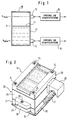
- Fig. 1 shows a container 10 which is filled to a height H with a liquid 11.
- the fill level should not exceed a maximum height H max and a minimum height H min .
- Each of these limit values of the fill level is also called "limit level".
- a fill level sensor 13 is attached to the outside of the container wall 12 and is connected to an excitation and evaluation electronics 14.
- a fill level sensor 15 is attached to the outside of the container wall 12 and is connected to an excitation and evaluation electronics 16.
- Each of the two sensors 13 and 15 is designed so that it can be used to determine through the container wall 12 whether or not the liquid 11 in the container 10 is at the level of the sensor 13 or 15.
- each of the two sensors 13 and 15 is designed as an ultrasonic sensor, which is capable of emitting an ultrasonic pulse toward the container wall 12 when excited by an electrical AC voltage pulse, which is supplied by the associated excitation and evaluation circuit 14 or 16 and convert received ultrasound signals into electrical AC signals that are transmitted to electronics 14 and 16, respectively.
- Electronics 14 and 16 evaluate the received signals and emit a signal at the output which indicates whether the fill level in container 10 is above or below the limit level to be monitored. For this determination it is therefore not necessary to break through the container wall 14 or to insert the sensor into the interior of the container 10. For this reason, the sensors 14 and 16 are also not in direct contact with the liquid 11.
- the two sensors 13 and 15 and the associated electronics 14 and 16 are of completely identical design. Therefore, only sensor 13 and electronics 14 will be described below described in detail. This description applies in the same way to the sensor 15 and the electronics 16.
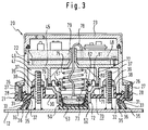
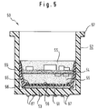
- FIG. 2 shows a perspective view of the sensor 13, and FIGS. 3 and 4 show sectional views of the sensor 13 attached to the container wall 12.
- FIG. 3 shows a longitudinal section of the sensor 13 in the event that the container wall is flat, and 4 shows a cross section through the sensor in the event that the container wall is cylindrical.
- the sensor shown in FIG. 2 consists of a sensor block 20, which contains all components of the ultrasonic sensor and the excitation and evaluation electronics, and an adapter 21, which is used to attach the sensor block 20 to containers of different shapes and sizes and from different materials fasten.
- the sensor block 20 has a sensor housing 22 which is closed by a cover 23 which is fastened on the sensor housing 22 by means of screws 24.
- the sensor block 20 is fastened to the adapter 21 by means of screws 26 which pass through bores in projections 27 on the narrow sides of the sensor housing 22 and are screwed into threaded bores in corresponding projections 28 on the adapter 21. After loosening the two screws 26, the complete sensor block can be removed from the adapter 21 attached to the container wall 12.
- the adapter 21 is fastened in a suitable manner without the sensor block 20 at the desired location on a container wall, and then the sensor block 20 with the ready-to-use mounted ultrasonic sensor is placed on the adapter 21 and fastened by means of the screws 26.
- a connection block 29 projecting laterally from the sensor housing 22 enables the electronics housed in the sensor housing 22 to be connected to external connection conductors.
- the adapter 21 is a molded plastic part which essentially consists of a plate 30, the outline of which corresponds to the outline of the sensor housing 22, that is to say is rectangular in the example shown.
- a frame 31 is formed around the circumference of the plate 30 and is provided on the side facing the container wall with a groove 32 into which a seal 33 is inserted.
- the frame 31 has a constant height on the long sides of the adapter 21, which in the case of a cylindrical container 10 lie along the surface lines on the container wall 12.
- the frame 31 On the transverse sides, which in the case of a cylindrical container 10 abut the container wall 12 along the circumference, the frame 31 has an arcuate recess 34, as can be seen in FIG. 2 on the front transverse side.
- the radius of curvature of the recess 34 corresponds to the radius of the container wall 12 of the container 10 with the smallest diameter to which the adapter 21 is to be attached. If the ultrasonic sensor 13 is intended for containers whose nominal width (diameter) is at least 200 mm, the radius of curvature of the recess 34 is therefore 100 mm.
- the seal 33 is designed such that its sealing surface intended for contact with the container wall lies in one plane when the adapter 21 has not yet been attached to the container wall 12 and the seal 33 has therefore not yet been deformed.
- the seal 33 has a constant height along the longitudinal sides of the frame 31, while its height in the region of each transverse side increases in the shape of an arc toward the center in accordance with the shape of the recess 34.
- the seal 33 is preferably formed with two sealing lips 35, between which there is a notch 36.
- the sealing lips 35 are relatively low along the long sides of the frame 31 (FIG. 4), and the depth of the notch 36 is correspondingly small there.
- the height of the sealing lips 35 and the depth of the notch 36 increase to the same extent as the height of the seal 33. Since the sectional plane of the sectional view of FIG. 3 passes through the locations at which the recesses 34 have their greatest depth, in this sectional view the sealing lips 35 have their greatest height and the notches 36 have their greatest depth.
- the sealing lips 35 in the region of the recesses 34 are compressed to the same extent as in the region of the straight longitudinal sides of the frame 31, that is to say relatively little. If, on the other hand, the adapter 21 is attached to a cylindrical container wall 12 (FIG. 4), the sealing lips in the region of the recesses 34 are deformed more than in the region of the straight longitudinal sides of the frame 31, and the more so, the smaller the radius of curvature of the container wall 12 is. This greater deformation is made possible by the greater height of the sealing lips 35 and the greater depth of the notch 36 in this area. In all cases, however, the sealing lips 35 lie sealingly against the container wall 12 along the entire circumference of the adapter 21.
- FIG. 3 shows a first possibility of fastening the adapter 21 to the container wall 12: threaded bolts 37 are welded to the container wall 12, which protrude through the openings of bushings 38, which are integrally formed on the plate 30 of the adapter 21. Nuts 39 are screwed onto the ends of the threaded bolts 37 which protrude from the bushes 38 and which clamp the plate 30 against the container wall 12 by compressing the seal 31. If appropriate, spacers projecting downward from the plate 30 to the container wall 12 can be formed, which determine a defined distance of the plate 30 from the container wall 12 and thereby a defined position of the adapter 21 with respect to the container wall 12.
- FIG. 4 Another type of attachment of the adapter 21 to the container wall 12 is shown in the left half of FIG. 4.
- a leg of an angle piece 41 made of strong sheet metal is inserted into a lateral slot 40, which is provided in the middle of each long side of the adapter 21, and is fastened therein by means of a screw 42.
- the other leg of the angle piece 40 which is bent upwards at right angles, is bent at the end in a hook shape.
- This hook-shaped bent end comprises a rail 43 which is welded to the container wall 12, and it is clamped to the rail 43 by means of at least one screw 44.
- This type of fastening makes it possible in a simple manner to determine the location at which the sensor 13 is to be attached to the container 10 and, if necessary, to change it subsequently by moving the adapter 21 along the rail 38.
- the hooking of the tension band 49 at the upper ends of the upwardly bent legs of the angle pieces 41 has the result that the points of application of the force exerted by the tension band 49 on the adapter 21 are relatively high. This is advantageous because, particularly in the case of containers with a large radius of curvature, the force component pressing against the container increases significantly with the height of the point of application.
- the threaded bolts 37 or the rails 43 can also be fastened to the container wall 12 by gluing instead of by welding. This type of attachment of the adapter 21 is then also suitable for plastic containers.
- the sensor housing 22 is divided into two rooms 46 and 47 by a transverse wall 45.
- the excitation and evaluation electronics 14 are accommodated, which in the usual way consist of electronic components which are mounted on a circuit board 48.
- the components of the ultrasonic sensor 13 are mounted in the inner space 47 facing the container wall 12 and the adapter 21.
- this includes an electroacoustic transducer 50, which serves to convert an AC voltage pulse supplied by the excitation and evaluation circuit into an ultrasound pulse that is transmitted to the container wall 12, and to convert ultrasound vibrations that it receives from the container wall 12 into an electrical AC voltage , which is transmitted to the excitation and evaluation circuit.
- the electroacoustic transducer 50 is shown in more detail in FIG. 5.
- an active component it contains a piezoelectric element 51, which in a known manner is a disk made of a piezo crystal, on both sides of which metallizations are applied, which serve as electrodes.
- the piezo crystal When an AC voltage is applied to the electrodes, the piezo crystal is excited to mechanical vibrations at the frequency of the AC voltage, and when mechanical vibrations are transmitted to the piezo crystal, it generates an AC voltage at the frequency of the mechanical vibrations between the electrodes.
- the electrodes are not shown in FIG. 5 because they are not visible due to the small thickness of the metallization compared to the thickness of the piezo crystal.
- the piezoelectric element 51 is arranged inside a cup-shaped transducer housing 52 and lies on the Bottom 53 of the transducer housing 52, which also forms the membrane of the ultrasonic transducer 50.
- the converter housing 52 is made of plastic.
- a circuit board 54 On the side of the piezoelectric element 51 facing away from the membrane 53, a circuit board 54 is arranged which carries the components of a circuit which is used to couple the piezoelectric element 51 to the excitation and evaluation electronics 14.
- the circuit board 54 is located at a distance from the piezoelectric element 51, and the space between the circuit board 54 and the piezoelectric element 51 is filled with a potting compound 55, which is filled in in the liquid state and then solidifies.
- the side of the piezoelectric element 51 facing away from the membrane 53 is covered with a disk 56 made of a closed-cell foam which prevents the potting compound 55 from coming into direct contact with the piezoelectric element 51.
- the space above the circuit board 54 is also filled with the potting compound 55 to such a height that all circuit components mounted on the circuit board 54 are embedded in the potting compound 55.
- the potting compound 55 is prescribed for reasons of explosion protection. It also has the effect of damping the ultrasound waves which are emitted on the side opposite the membrane 53.
- a mounting sleeve 60 is provided, which is shown in more detail in FIGS. 6, 7 and 8.
- the mounting sleeve 60 is a molded body made of plastic, which is shown in FIG. 6 in plan view, in FIG. 7 in longitudinal section along broken line AA of FIG. 6 and in FIG. 8 in perspective view.
- the mounting sleeve 60 has a wider cylindrical section 61, a narrower cylindrical section 62 of smaller diameter and a conical section 63 between the two cylindrical sections 61 and 62.
- the outer diameter of the wider one cylindrical section 61 corresponds to the inner diameter of the pot-shaped converter housing 52, and the inner diameter of the narrower cylindrical section 62 corresponds to the diameter of the piezoelectric element 51.
- the narrower cylindrical section 62 and the conical transition section 63 are divided into six segments 64 by cutouts.
- a radially inwardly projecting paw 65 is formed on each segment 64 at the transition between the cylindrical section 61 and the conical section 63.
- a stop nose 66 is formed below each paw 65, which extends downward only over part of the height of the cylindrical section 62 and projects only slightly radially inwards.
- a shoulder 67 is formed at the transition between the conical section 63 and the wider cylindrical section 61.
- an elastic catch 68 is formed at two diametrically opposite locations by cutouts, the free end of which projects slightly inwards and lies at a distance from the shoulder 67 which corresponds to the thickness of the circuit board 54.
- a rib 69 formed on the circumference of the wider cylindrical section 61 engages in a corresponding groove in the converter housing 52, as a result of which the mounting sleeve 60 in the converter housing 52 is secured against rotation.
- the described design of the mounting sleeve 60 allows a simple, quick and precise assembly of the components of the ultrasonic transducer 50 outside the transducer housing 52.
- the piezoelectric element 51 with the disk 56 made of closed-cell foam placed thereon is inserted from below into the narrower cylindrical section 62 until the piezoelectric element 51 abuts the ends of the stop lugs 66.
- the radial and axial position of the piezoelectric element 51 in the mounting sleeve 60 is precisely defined.
- the diameter of the foam disc 56 is slightly smaller than the diameter of the piezoelectric element 51 and corresponds to the distance between two stop lugs 66 diametrically opposite one another, and the thickness of the foam disk 56 corresponds to the height of the stop lugs 66.
- the paws 65 rest on the top of the foam disk 56 when the piezoelectric element 51 is inserted as far as possible into the mounting sleeve 60, and the stop lugs 66 abut the circumference of the foam disc 56.
- the radial and axial position of the foam disc 56 in the mounting sleeve 60 is precisely defined, and the foam disc 56 is held in close contact with the top surface of the piezoelectric element 51 by the paws 65.
- the circuit board 54 is circular with a diameter that corresponds to the inner diameter of the wider cylindrical portion 61 of the mounting sleeve 60. It is inserted into the wider cylindrical section 61 from above until it rests on the shoulder 67. During insertion, the catches 68 are pushed outward from the peripheral edge of the circuit board 54 until the peripheral edge of the circuit board 54 has passed the ends of the catches 68. Then, the catches 68 protrude inward again due to their elasticity, so that they grip over the top of the circuit board 54 and hold it on the shoulder 67. As a result, the circuit board 54 is also fixed in the mounting sleeve 60 in the axial and radial directions.
- the mounting sleeve 60 is ready for installation in the pot-shaped converter housing 52.
- a drop of a thermosetting adhesive is first applied to the bottom 53 of the converter housing 52, and then the mounting sleeve 60 is inserted into the converter housing 52 until the piezoelectric element 51 touches the bottom 53.
- the adhesive is distributed in a thin layer between the mutually facing surfaces of the piezoelectric element 51 and the base 53.
- the adhesive is hardened by heating, the mounting sleeve 60 being weighted down with a weight so that a defined adhesive layer is obtained.
- the adhesive layer ensures the contact between the piezoelectric element 51 and the membrane of the ultrasonic transducer 50 formed by the bottom 53 and prevents the formation of an air layer between these parts.
- potting compound 55 is poured into the mounting sleeve 60 from above.
- This potting compound flows through openings provided for this purpose in the circuit board 54 and also into the space between the circuit board 54 and the foam disk 56.
- the foam disk 56 prevents the potting compound 55 from coming into contact with the upper side of the piezoelectric element 51.
- the paws 65 which press the edge of the foam disc 56 onto the upper side of the piezoelectric element 51, prevent casting compound 55 from creeping between the foam disc 56 and the piezoelectric element 51.
- a mounting part 70 with a flange 71, on which a guide bush 72 is formed, is used to mount the pot-shaped converter housing 52 in the sensor housing 22.
- the converter housing 52 is inserted into the guide bush 72, the inside diameter of which corresponds to the outside diameter of the converter housing 52, so that the converter housing 52 is slidably mounted in the guide bush 72.
- the collar 57 on the converter housing 52 prevents the converter housing 52 from emerging from the guide bush 72.
- a spring cup 73 is inserted into the open end of the converter housing 52, which in turn has a collar 74 which is supported at the end of the converter housing 52.
- the spring cup 73 receives one end of a helical compression spring 75.
- a collar 76 runs around the edge of the flange 71, the inside diameter of which corresponds to the outside diameter of a support tube 77 formed on the transverse wall 45.
- a connecting line 78 which is soldered to the circuit board 54 and is intended for connecting the ultrasound transducer 50 to the excitation and evaluation electronics 16, is passed through one of the transverse walls 45 to the opposite one Side protruding pipe socket 79 performed.
- a sealing ring 80 is placed on the flange 71, to which the outer edge of an annular sleeve 81 is fastened, the inner edge of which is connected to an elastic ring 82 placed around the converter housing 52. Then the collar 76 is pushed over the support tube 77 and the flange 71 is fastened to the support tube 77 by means of screws 83 which are screwed into thickened wall sections of the support tube 77 and one of which is visible in FIG.
- the spring 75 is dimensioned such that it is compressed between the spring cup 73 and the transverse wall 45 to achieve a desired pretension when the holding part 70 is fastened to the carrier tube 77.
- the connecting line 78 can then be soldered to the connection points provided on the circuit board 48, and the outer space 41 can be filled with a casting compound almost up to the height of the pipe socket 79.
- the pipe socket 79 prevents the potting compound from flowing into the inner space 42.
- the sensor block 20 is thus assembled ready for operation, and it can be attached to the adapter 21.
- the guide bush 72 is inserted through an opening in the plate 30 of the adapter 21, so that the bottom of the transducer housing 72, ie the membrane 53 of the ultrasonic transducer 50, is placed against the outside of the container wall 12.
- the converter housing 52 is held by the container wall 12 so that it is pushed into the guide bush 72, whereby the spring 75 is further compressed.
- the membrane 23 is pressed against the container wall 12 with a pressure force determined by the spring 75.
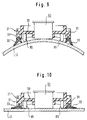
- FIGS. 9 and 10 schematically show a preferred embodiment of the adapter 21 with which this condition is met.
- spacers 85 are attached to the adapter 21, which determine the distance of the plate 30 from the container wall 12 along two lines running parallel to the long sides of the adapter.
- the spacers 85 can be pins that are attached to the four corners of the plate 30 or strips that extend along the long sides of the frame 31.
- the spacers 85 ensure that the adapter 21 has a defined position with respect to the container wall 12, even if the force acting on one side is greater than the force acting on the other side when the tension band is fastened, or if the bolts are not when fastened by means of threaded bolts are precisely aligned or the forces exerted by the nuts are unequal.
- the converter housing 52 shown schematically in FIGS. 9 and 10 shows that, as a result of the spacers 85 in the case of a cylindrical container wall 12, the membrane is aligned exactly tangentially and symmetrically to the container wall 12 and, in the case of a flat container wall 12, rests parallel to the container wall 12.
Landscapes
- Physics & Mathematics (AREA)
- Acoustics & Sound (AREA)
- Electromagnetism (AREA)
- Thermal Sciences (AREA)
- Fluid Mechanics (AREA)
- General Physics & Mathematics (AREA)
- Measurement Of Levels Of Liquids Or Fluent Solid Materials (AREA)
Applications Claiming Priority (2)
| Application Number | Priority Date | Filing Date | Title |
|---|---|---|---|
| DE19538677 | 1995-10-17 | ||
| DE19538677A DE19538677C2 (de) | 1995-10-17 | 1995-10-17 | Anordnung zur Überwachung eines vorbestimmten Füllstands einer Flüssigkeit in einem Behälter |
Publications (2)
| Publication Number | Publication Date |
|---|---|
| EP0769683A2 true EP0769683A2 (fr) | 1997-04-23 |
| EP0769683A3 EP0769683A3 (fr) | 1998-03-04 |
Family
ID=7775099
Family Applications (1)
| Application Number | Title | Priority Date | Filing Date |
|---|---|---|---|
| EP96116314A Withdrawn EP0769683A3 (fr) | 1995-10-17 | 1996-10-11 | Système de surveillance d'un niveau prédéterminé d'un fluide dans un récipient |
Country Status (6)
| Country | Link |
|---|---|
| US (1) | US5778726C1 (fr) |
| EP (1) | EP0769683A3 (fr) |
| JP (1) | JP3007303B2 (fr) |
| CA (1) | CA2187846C (fr) |
| DE (1) | DE19538677C2 (fr) |
| ZA (1) | ZA968358B (fr) |
Cited By (1)
| Publication number | Priority date | Publication date | Assignee | Title |
|---|---|---|---|---|
| WO2023285184A1 (fr) * | 2021-07-14 | 2023-01-19 | Endress+Hauser Flowtec Ag | Dispositif d'automatisation de terrain |
Families Citing this family (19)
| Publication number | Priority date | Publication date | Assignee | Title |
|---|---|---|---|---|
| US5844491A (en) * | 1997-04-30 | 1998-12-01 | Endress + Hauser Gmbh + Co. | Apparatus for establishing and/or monitoring a predetermined filling level in a container |
| US6801575B1 (en) * | 1997-06-09 | 2004-10-05 | Sharp Laboratories Of America, Inc. | Audio/video system with auxiliary data |
| US6128967A (en) * | 1999-04-20 | 2000-10-10 | Seh America, Inc. | Level transmitter connector |
| US20050183346A1 (en) * | 2003-07-28 | 2005-08-25 | Dudley William E. | Air conditioning condensation drainage system |
| US7117738B2 (en) * | 2003-10-02 | 2006-10-10 | Denso Corporation | Liquid level detecting apparatus |
| US7245059B2 (en) * | 2004-05-17 | 2007-07-17 | Xtero Datacom Inc. | Method of exciting a piezoelectric crystal |
| US7287425B2 (en) * | 2004-05-17 | 2007-10-30 | Xtero Datacom Inc. | Ultrasonic fuel level monitoring device |
| JP4981328B2 (ja) * | 2006-02-16 | 2012-07-18 | リコーエレメックス株式会社 | 水準器 |
| US7905143B2 (en) * | 2007-07-23 | 2011-03-15 | Schmitt Measurement Systems, Inc. | Ultrasonic fuel level monitoring system incorporating an acoustic lens |
| US8104341B2 (en) * | 2009-03-25 | 2012-01-31 | Schmitt Measurement Systems, Inc. | Ultrasonic liquid level monitoring system |
| US8412473B2 (en) | 2011-04-11 | 2013-04-02 | Schmitt Industries, Inc. | Event monitoring and detection in liquid level monitoring system |
| FR3033040B1 (fr) * | 2015-02-24 | 2017-03-17 | Electricite De France | Dispositif de fixation d'un capteur a un objet et son procede de montage |
| US11946790B2 (en) | 2015-08-29 | 2024-04-02 | Mopeka Products Llc | Sensor arrangements, sensor systems, and methods for determining height of liquids in tanks |
| US12174053B1 (en) | 2015-08-29 | 2024-12-24 | Mopeka Products Llc | Tank sensors |
| US10571328B2 (en) * | 2015-08-29 | 2020-02-25 | Mopeka Products Llc | Sensor arrangements, sensor systems, and methods for determining height of liquids in tanks |
| SE540928C2 (en) * | 2017-06-20 | 2018-12-27 | Acosense Ab | A holding arrangement for an acoustic transmitter in an acoustic spectroscopy system |
| FR3092168B1 (fr) * | 2019-01-24 | 2021-08-06 | Dehon Sa | Système et procédé de mesure par ondes acoustiques du niveau de remplissage d’un réservoir de fluide |
| AT17018U1 (fr) * | 2019-10-29 | 2021-02-15 | Tdk Electronics Ag | |
| CN112747798B (zh) * | 2021-02-05 | 2024-10-25 | 北京市计量检测科学研究院(北京市能源计量监测中心) | 一种超声流量计探头的安装夹具及其安装方法 |
Family Cites Families (15)
| Publication number | Priority date | Publication date | Assignee | Title |
|---|---|---|---|---|
| US3296586A (en) * | 1965-05-18 | 1967-01-03 | Lab For Electronics Inc | Transducer and housing assembly |
| JPS5212860A (en) * | 1975-07-21 | 1977-01-31 | Sanko Kuki Sochi Kk | Level detector |
| US4144517A (en) * | 1977-08-05 | 1979-03-13 | Joseph Baumoel | Single transducer liquid level detector |
| DE2743394C3 (de) * | 1977-09-27 | 1980-06-26 | Endress U. Hauser Gmbh U. Co, 7867 Maulburg | Vorrichtung zur Befestigung eines für die Füllstandsmessung bestimmten Schall- oder Ultraschallwandlers an einem Behälter |
| US4320659A (en) * | 1978-02-27 | 1982-03-23 | Panametrics, Inc. | Ultrasonic system for measuring fluid impedance or liquid level |
| DE3431741A1 (de) * | 1984-08-29 | 1986-03-13 | Siemens AG, 1000 Berlin und 8000 München | Vorrichtung zur messung des fuellstandes von fluessigkeiten |
| IT8453987U1 (it) * | 1984-10-31 | 1986-05-01 | Hospal Dasco Spa | Dispositivo rivelatore della presenza di fluido in corrispondenza di un prefissato livello di un contenitore di liquido |
| DE3609461A1 (de) * | 1986-03-20 | 1987-09-24 | Siemens Ag | Elektroakustischer wandler |
| DE3633047A1 (de) * | 1986-09-29 | 1988-04-07 | Endress Hauser Gmbh Co | Fuellstandmessgeraet zur messung des fuellstandes von explosiblen oder aggresiven medien in einem behaelter |
| DE3933474C2 (de) * | 1989-10-06 | 1994-01-27 | Endress Hauser Gmbh Co | Füllstandsmeßgerät |
| DE4008135A1 (de) * | 1990-03-14 | 1991-09-19 | Endress Hauser Gmbh Co | Vorrichtung zur feststellung und/oder ueberwachung eines vorbestimmten fuellstands in einem behaelter |
| US5586085A (en) * | 1991-10-31 | 1996-12-17 | Lichte; Leo J. | Container and adaptor for use with fluid volume sensor |
| DE4240690C2 (de) * | 1992-03-24 | 1995-03-16 | Endress Hauser Gmbh Co | Ultraschallwandler |
| US5201222A (en) * | 1992-05-29 | 1993-04-13 | Edo Corporation | Vessel level sensor mounting structure with positive mechanical lock |
| US5438868A (en) * | 1993-11-01 | 1995-08-08 | Zevex, Inc. | Noninvasive ultrasonic liquid level indicator |
-
1995
- 1995-10-17 DE DE19538677A patent/DE19538677C2/de not_active Expired - Fee Related
-
1996
- 1996-10-04 ZA ZA9608358A patent/ZA968358B/xx unknown
- 1996-10-11 EP EP96116314A patent/EP0769683A3/fr not_active Withdrawn
- 1996-10-15 CA CA002187846A patent/CA2187846C/fr not_active Expired - Fee Related
- 1996-10-16 US US08733098 patent/US5778726C1/en not_active Expired - Fee Related
- 1996-10-17 JP JP8274893A patent/JP3007303B2/ja not_active Expired - Fee Related
Cited By (1)
| Publication number | Priority date | Publication date | Assignee | Title |
|---|---|---|---|---|
| WO2023285184A1 (fr) * | 2021-07-14 | 2023-01-19 | Endress+Hauser Flowtec Ag | Dispositif d'automatisation de terrain |
Also Published As
| Publication number | Publication date |
|---|---|
| US5778726C1 (en) | 2001-09-11 |
| DE19538677C2 (de) | 1998-12-17 |
| JPH09126868A (ja) | 1997-05-16 |
| CA2187846C (fr) | 2000-09-26 |
| ZA968358B (en) | 1997-12-29 |
| DE19538677A1 (de) | 1997-04-24 |
| JP3007303B2 (ja) | 2000-02-07 |
| CA2187846A1 (fr) | 1997-04-18 |
| EP0769683A3 (fr) | 1998-03-04 |
| US5778726A (en) | 1998-07-14 |
Similar Documents
| Publication | Publication Date | Title |
|---|---|---|
| EP0769683A2 (fr) | Système de surveillance d'un niveau prédéterminé d'un fluide dans un récipient | |
| DE19538696C2 (de) | Anordnung zur Überwachung eines vorbestimmten Füllstands einer Flüssigkeit in einem Behälter | |
| EP0769685A2 (fr) | Système de surveillance d'un niveau prédéterminé d'un fluide dans un récipient | |
| EP0769682A2 (fr) | Système de surveillance d'un niveau prédéterminé d'un fluide dans un récipient | |
| DE3215040C2 (de) | Resonanzstab | |
| DE69502027T2 (de) | Schwingungsdämpfende, hydraulische stütze | |
| EP0182013A2 (fr) | Dispositif pour la fixation d'un premier élément de construction | |
| DE102021127943B3 (de) | Magnetisch-induktives Durchflussmessgerät | |
| DE3234060C2 (de) | Elektrostatischer Wandler | |
| EP1471341A1 (fr) | Fixation d'un capteur à petite construction sur un réservoir au moyen d'une vis de pression concentrique | |
| DE3837419A1 (de) | Bremsgeraet fuer eine hydraulische fahrzeugbremsanlage | |
| EP0909223B1 (fr) | Transducteur ultrasonique avec element de contact | |
| EP1117151A1 (fr) | Cosse de câble | |
| DE4232457C2 (de) | Elektroakustischer Wandler | |
| DE19639075B4 (de) | Befestigungseinrichtung für einen Sensor | |
| CH680625A5 (fr) | ||
| DE10019082B4 (de) | Träger für eine Vorrichtung zum Messen des Reifendrucks zur Verwendung in einem auf einer Felge montierten Luftreifen und damit ausgestattetes Rad | |
| DE2331752C2 (de) | Einrichtung zur druckdichten Durchführung eines Verbindungsrohres durch zwei miteinander verspannbare Bauteile | |
| DE60009401T2 (de) | Vorrichtung zum Befestigen eines Hitzeschildes für eine Ölpumpe | |
| DE9310630U1 (de) | An einer Montagefläche befestigtes elektrisches Gerät | |
| DE19758008B4 (de) | Anordnung zur Abstützung und Fixierung einer Schraubenfeder auf einem Achslenker einer Fahrzeugachse | |
| DE19928302B4 (de) | Vorrichtung zum Befestigen von Seilzugelementen | |
| EP0877458A2 (fr) | Dispositif de connexion et de montage | |
| EP0266656A2 (fr) | Dispositif de suspension pouvant être monté automatiquement | |
| EP1592601A1 (fr) | Fixation d'une piece de vehicule sur une structure de carrosserie de vehicule |
Legal Events
| Date | Code | Title | Description |
|---|---|---|---|
| PUAI | Public reference made under article 153(3) epc to a published international application that has entered the european phase |
Free format text: ORIGINAL CODE: 0009012 |
|
| AK | Designated contracting states |
Kind code of ref document: A2 Designated state(s): DE FR GB IT |
|
| PUAL | Search report despatched |
Free format text: ORIGINAL CODE: 0009013 |
|
| AK | Designated contracting states |
Kind code of ref document: A3 Designated state(s): DE FR GB IT |
|
| 17P | Request for examination filed |
Effective date: 19980623 |
|
| RAP1 | Party data changed (applicant data changed or rights of an application transferred) |
Owner name: ENDRESS + HAUSER GMBH + CO.KG. |
|
| 17Q | First examination report despatched |
Effective date: 20070808 |
|
| STAA | Information on the status of an ep patent application or granted ep patent |
Free format text: STATUS: THE APPLICATION IS DEEMED TO BE WITHDRAWN |
|
| 18D | Application deemed to be withdrawn |
Effective date: 20071219 |