EP0769752A2 - Löschgerät für magnetische Anzeige - Google Patents
Löschgerät für magnetische Anzeige Download PDFInfo
- Publication number
- EP0769752A2 EP0769752A2 EP96307591A EP96307591A EP0769752A2 EP 0769752 A2 EP0769752 A2 EP 0769752A2 EP 96307591 A EP96307591 A EP 96307591A EP 96307591 A EP96307591 A EP 96307591A EP 0769752 A2 EP0769752 A2 EP 0769752A2
- Authority
- EP
- European Patent Office
- Prior art keywords
- magnetic
- erasing head
- erasing
- card
- magnetic field
- Prior art date
- Legal status (The legal status is an assumption and is not a legal conclusion. Google has not performed a legal analysis and makes no representation as to the accuracy of the status listed.)
- Withdrawn
Links
Images


Classifications
-
- G—PHYSICS
- G06—COMPUTING OR CALCULATING; COUNTING
- G06K—GRAPHICAL DATA READING; PRESENTATION OF DATA; RECORD CARRIERS; HANDLING RECORD CARRIERS
- G06K7/00—Methods or arrangements for sensing record carriers, e.g. for reading patterns
- G06K7/08—Methods or arrangements for sensing record carriers, e.g. for reading patterns by means detecting the change of an electrostatic or magnetic field, e.g. by detecting change of capacitance between electrodes
- G06K7/082—Methods or arrangements for sensing record carriers, e.g. for reading patterns by means detecting the change of an electrostatic or magnetic field, e.g. by detecting change of capacitance between electrodes using inductive or magnetic sensors
-
- G—PHYSICS
- G09—EDUCATION; CRYPTOGRAPHY; DISPLAY; ADVERTISING; SEALS
- G09F—DISPLAYING; ADVERTISING; SIGNS; LABELS OR NAME-PLATES; SEALS
- G09F9/00—Indicating arrangements for variable information in which the information is built-up on a support by selection or combination of individual elements
- G09F9/30—Indicating arrangements for variable information in which the information is built-up on a support by selection or combination of individual elements in which the desired character or characters are formed by combining individual elements
- G09F9/37—Indicating arrangements for variable information in which the information is built-up on a support by selection or combination of individual elements in which the desired character or characters are formed by combining individual elements being movable elements
- G09F9/375—Indicating arrangements for variable information in which the information is built-up on a support by selection or combination of individual elements in which the desired character or characters are formed by combining individual elements being movable elements the position of the elements being controlled by the application of a magnetic field
Definitions
- the present invention relates to a magnetic display erasing apparatus for a medium such as a magnetic card, having a magnetic display portion for displaying visible information by the action of a magnetic field.
- magnetic cards in which magnetic stripes elongate along the longitudinal direction thereof are widely used in various fields such as bank cards, credit cards and ID cards.
- a magnetic stripe is recorded, for example, an identification code of a user of the card, as patterns of orientations or strengths of magnetization.
- a magnetic card of another type in which a magnetic display sheet which contains a micro capsule sensitive to a magnetic field is formed at a position other than the position of a magnetic stripe (for example, Japanese Unexamined Patent Publication JP-A 6-168369 (1994)).
- a magnetic display sheet which contains a micro capsule sensitive to a magnetic field is formed at a position other than the position of a magnetic stripe
- flat magnetic sensitive flakes are encapsulated together with a liquid.
- the magnetic sensitive flakes are oriented in parallel, so that the optical reflectivity is increased with the result that the magnetic display sheet becomes bright.
- a magnetic field vertical to the card substrate is applied to the micro capsule, the magnetic sensitive flakes are vertically oriented, so that the optical reflectivity is reduced with the result that the magnetic display sheet becomes dark.
- the magnetic display sheet can display visible information such as characters and symbols in accordance with the applied magnetic field. Consequently, the magnetic card is remarkably improved in ease of use.
- a recording head for writing is such constructed that a number of cores, on each of which a coil is wound, are arranged at regular pitches.
- the coils of the recording head are selectively energized in accordance with an external signal.
- a beam-like magnetic flux is produced from the front end of each core and spot-like vertical magnetic fields are applied to the magnetic display sheet.
- the portions to which the vertical magnetic field is applied are dark and those to which the vertical magnetic field is not applied remain bright.
- an erasing operation will be described.
- an erasing head for example, permanent magnets are arranged so that both the N- and S-poles face the card, thereby producing magnetic fields parallel to the card substrate.
- the magnetic card is conveyed by a conveyor or the like so as to be moved in the proximity of the erasing head.
- the magnetic fields produced by the permanent magnets constitute a magnetic field parallel to the magnetic display sheet. Therefore, the magnetic sensitive flakes in the micro capsules are laterally directed, so that the whole of the magnetic display sheet becomes bright and the information is erased.
- a magnetic card in which a magnetic display sheet and a magnetic recording portion such as a magnetic stripe are formed, there is a case where invisible information of the magnetic recording portion is read out or rewritten while preserving visible information of the magnetic display sheet as they are.
- the operation of adding the new visible information must be performed in a manner that the existing visible information is not erased. Therefore, in the magnetic display erasing apparatus having the erasing head in which the permanent magnets continually producing an erasing magnetic field are arranged, since the erasing operation is always performed, such a mechanism or the like is required which allows the unerasing operation to be selectively performed.
- the apparatus of Japanese Unexamined Patent Publication JP-A 6-168369 (1994) has a configuration in which an arm supporting the erasing head is vertically movable so that the erasing head is downward retracted from the card convey path, whereby the magnetic display sheet is prevented from being affected by the erasing magnetic field of the erasing head.
- the retracting distance of the erasing head is not sufficiently long, however, there arises a possibility that the magnetic display sheet is partly erased or erroneous characters are written into the magnetic display sheet. In order to ensure the reliability, therefore, it is required to provide the erasing head with a sufficiently long retracting distance. This means the miniaturization of the whole of the apparatus is a problem.
- the apparatus When a magnetic card having both a magnetic stripe and a magnetic display sheet is to be handled, moreover, the apparatus must be configured so that the operation of retracting the erasing head does not adversely affect also the magnetic stripe. This imposes further restrictions on the design of such an apparatus.
- the invention provides a magnetic display erasing apparatus comprising an erasing head which produces a magnetic field and erases visible information written into a magnetic display medium which is conveyed relatively with respect to the erasing head, by an action of the magnetic field, the magnetic display erasing apparatus further comprising: magnetic shielding means for weakening the magnetic field produced by the erasing head during a non-erasing operation to an extent that display contents of the magnetic display medium are not affected by the magnetic field.
- the erasing magnetic field of the erasing head is weakened by the magnetic shielding means to an extent that the magnetic field does not affect visible information of a magnetic display portion. Therefore, it is not required to reserve a long moving distance of the erasing head. Consequently, the apparatus can be miniaturized and restrictions on the design are relaxed.
- the magnetic shielding means can house the erasing head.
- the erasing magnetic field of the erasing head is surely weakened. Therefore, it is not required to reserve a long moving distance of the erasing head. Consequently, the apparatus can be miniaturized and restrictions on the design are relaxed.
- the apparatus further comprises moving means for moving at least one of the erasing head and the magnetic shielding means.
- One or both of the erasing head and the magnetic shielding means can be moved, and hence the erasing magnetic field may be weakened by a small-sized and simple mechanism.
- the magnetic shielding means is attached to the erasing head.
- a part of the erasing magnetic field produced by the erasing head may be weakened also during an erasing operation, the erasing magnetic field part being irrelevant to the erasure of the magnetic display portion.
- the erasing magnetic field can be weakened by the magnetic shielding means attached to the erasing head. Consequently, the erasing apparatus can be realized by a small-sized and simple mechanism.
- the erasing head comprises a portion which produces the magnetic field and another portion where the magnetic shielding means is disposed, and one of the portions selectively opposes the magnetic display medium by inversion or movement of the erasing head.
- the space required for moving the erasing head can be very small, and hence the erasing magnetic field can be weakened by a small-sized and simple mechanism.
- the movement direction of the erasing head or magnetic shielding means is parallel to a magnetic display medium conveying plane.
- the invention provides a magnetic display erasing apparatus comprising an erasing head which produces a magnetic field and erases visible information written into a magnetic display medium which is conveyed relatively with respect to the erasing head, by an action of the magnetic field, wherein the erasing head is retracted in the direction parallel to the magnetic display medium conveying plane.
- the apparatus by setting a movement direction of the erasing head or magnetic shielding means to the direction parallel to the magnetic display medium conveying plane, the apparatus can be reduced in thickness.
- the magnetic field can be weakened by using the magnetic shielding means to an extent that display information of the magnetic display portion is not affected by the magnetic field, whereby the action of the erasing head can be effectively eliminated. Therefore, it is not required to reserve a large moving mechanism for the erasing head and the like. Consequently, the apparatus can be miniaturized and restrictions on the design are relaxed.
- Fig. 1A is a perspective view showing a first embodiment of the invention
- Fig. 1B is a sectional view of the embodiment
- Fig. 1C is a sectional view showing a state where an erasing head is housed.
- a magnetic card 4 comprises a rectangular substrate which is made of plastics or the like.
- a magnetic stripe 6 is formed on a back face of the substrate adjacent one of the long edges.
- the magnetic stripe 6 is elongate in the longitudinal direction.
- a magnetic display sheet 3 is formed on the other face of the substrate arranged displaced from the longitudinal center of the sheet toward other long edge of the magnetic stripe 6.
- An erasing head 1 is disposed opposite the back face of the magnetic card 4 which is conveyed.
- a plurality of, for example, four permanent magnets 2a to 2d are arranged on the surface of the erasing head 1.
- the N- and S-poles of the permanent magnets 2a to 2d are oriented in the card conveying direction.
- the permanent magnets 2a to 2d are positioned slightly laterally progressively shifted in a sequential manner across the width of the magnetic display sheet 3 as it passes the head 1. According to this arrangement, a magnetic field directed from the N-pole to the S-pole is produced for each of the permanent magnets 2a to 2d, and erasing magnetic fields which are substantially parallel to each other are formed at a position where the magnetic display sheet 3 passes the erasing head 1.
- the operation of erasing the magnetic display sheet 3 will be described.
- the magnetic card 4 is conveyed by a belt conveyor or the like so as to be moved in the proximity of the erasing head 1
- the magnetic display sheet 3 passes through the parallel magnetic fields produced by the permanent magnets 2a to 2d.
- magnetic sensitive flakes in the micro capsules contained in the magnetic display sheet 3 are magnetized and laterally directed, so that the whole of the magnetic display sheet 3 becomes bright, and the erasing operation is thus completed.
- the erasing head 1 is moved laterally in a direction parallel to the card conveying plane by a moving mechanism which is not shown, so as to be retracted from the card path.
- a box-like magnetic shield 5 which is openable is disposed at the side of the card path.
- the erasing head 1 is housed in the magnetic shield 5 so as to be hermetically sealed.
- the magnetic shield 5 is made of a high-permeability ferromagnetic substance such as Fe, Ni, Co, or an alloy of these metals; Permalloy (trade name); or silicon steel so that flux from the erasing head 1 is substantially blocked and does not escape to the outside. Accordingly, the magnetic field from the erasing head 1 is weakened and cannot reach the magnetic display sheet 3.
- the disposition of the magnetic shield 5 in the vicinity of the card path can shorten the moving distance of the erasing head 1, thereby allowing the whole of the apparatus to be miniaturized.
- the retracting position of the erasing head 1 must be determined with regard also to the effect on the magnetic stripe 6.
- the use of the magnetic shield 5 can eliminate this consideration.
- the erasing head 1 can be retracted toward the magnetic stripe 6.
- the magnetic shield 5 may be moved, or both the erasing head 1 and the magnetic shield 5 are moved and then the former may be housed in the latter.
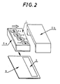
- Fig. 2 is a perspective view showing a second embodiment of the invention.
- the magnetic card 4 and the erasing head 1 are configured in the same manner as those shown in Fig. 1 and hence duplication of description is omitted.
- magnetic shields 5a and 5b are separated from each other.
- the one magnetic shield Sa is attached by an adhesive to the bottom face and one side face of the rectangular parallelopiped erasing head 1.
- the other magnetic shield 5b is configured so that, when the magnetic shield 5a is inserted, the shields form a flux blocking box.
- the operation of erasing the magnetic display sheet 3 is performed in the same manner as described above. Namely, when the magnetic card 4 is moved in the proximity of the erasing head 1, the visible information recorded on the magnetic display sheet 3 is erased by the parallel magnetic field produced by the permanent magnets 2a to 2d.
- the erasing head 1 is moved in a direction parallel to the card conveying plane by a moving mechanism which is not shown, so as to be retracted from the card path.
- the magnetic shields 5a and 5b are magnetically joined together so as to form one shield structure.
- leakage fluxes from the erasing head 1 are interrupted and hardly escape to the outside. Accordingly, the magnetic field from the erasing head 1 is weakened and cannot reach the magnetic display sheet 3.
- the moving distance of the erasing head 1 can be set to be short, with the result that the apparatus can be miniaturized and the degree of freedom of design is increased.
- the number of the separated magnetic shields is not limited to two and may be three or more. A configuration in which one or both of the magnetic shields 5a and 5b are moved may be employed.
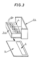
- Fig. 3 is a perspective view showing a third embodiment of the invention.
- the magnetic card 4 and the erasing head 1 are configured in the same manner as those shown in Fig. 1 and hence duplication of description is omitted.
- the magnetic shields 5a and 5b are rotatably supported so as to be openable.
- the one magnetic shield 5a is attached by an adhesive to the bottom face and one side face of the rectangular parallelopiped erasing head 1.
- the other magnetic shield 5b is configured in such a manner that, when the magnetic shield 5a is closed, the shields form a flux blocking box.
- the operation of erasing the magnetic display sheet 3 is performed in the same manner as described above. Namely, when the magnetic card 4 is moved in the proximity of the erasing head 1, the visible information recorded on the magnetic display sheet 3 is erased by the parallel magnetic fields produced by the permanent magnets 2a to 2d.
- the erasing head 1 is caused to be angularly displaced in the direction of the arrow by a moving mechanism which is not shown, so as to be retracted from the convey path.
- the magnetic shields 5a and 5b are magnetically joined together so as to form one shield structure.
- leakage fluxes from the erasing head 1 are interrupted and hardly escape to the outside. Accordingly, the magnetic field from the erasing head 1 is weakened and cannot reach the magnetic display sheet 3.
- the moving distance of the erasing head 1 can be set to be short, with the result that the apparatus can be miniaturized and restrictions on the design are relaxed.
- the number of the separated magnetic shields is not limited to two and may be three or more. A configuration in which one or both of the magnetic shields 5a and 5b are moved may be employed.
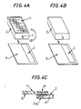
- Figs. 4A to 4C show a fourth embodiment of the invention
- Fig. 4A is a perspective view showing an erasing state
- Fig. 4B is a perspective view showing an non-erasing state
- Fig. 4C is a sectional view of Fig. 4B.
- the magnetic card 4 and the erasing head 1 are configured in the same manner as those shown in Fig. 1 and hence duplication of description is omitted.
- the erasing head 1 is formed so as to have a rectangular parallelopiped shape.
- the magnetic shield 5 is attached to the bottom face and four side faces of the erasing head.
- the erasing head 1 is disposed on the side of the back face of the card convey path, and supported by a rotating mechanism which is not shown, in such a manner that the erasing head 1 can be rotated about a shaft 7 about 180 degrees.
- the erasing head 1 When the magnetic display sheet 3 is to be erased, the erasing head 1 is positioned so that the erasing face thereof faces the card path. In the same manner as described above, when the magnetic card 4 is moved in the proximity of the erasing head 1, the visible information recorded on the magnetic display sheet 3 is erased by the parallel magnetic fields produced by the permanent magnets 2a to 2d.
- the erasing head 1 is turned over and then positioned so that the bottom face of the erasing head 1 is adjacent the card path, thereby attaining a posture in which the erasing face is most remote from the convey path.
- magnetic force emitted from the erasing face cannot reach the convey path.
- the existence of the magnetic shield 5 largely attenuates the magnetic field to such a degree that the magnetic field in the card path leaves the magnetic display sheet 3 substantially unaffected to any practical extent.
- the moving distance of the erasing head 1 can be set to be short, with the result that the apparatus can be miniaturized and the degree of freedom of the design is increased.
- Fig. 5 is a sectional view showing a fifth embodiment of the invention.
- the magnetic card 4 and the erasing head 1 are configured in the same manner as those shown in Fig. 1 and hence duplication of description is omitted.
- the erasing head 1 is formed so as to have a rectangular parallelopiped shape.
- the magnetic shield 5a is attached to the bottom face and four side faces of the erasing head 1.
- the erasing head 1 is disposed on the side of the back face of the card path in such a manner that the flat magnetic shield 5b can be inserted between the erasing head 1 and the card path.
- the magnetic shield 5b is moved by a moving mechanism which is not shown. so as to cover the erasing face of the erasing head 1.
- the magnetic shields 5a and 5b are magnetically joined together, thereby blocking the magnetic field extending from the erasing face of the erasing head 1.
- the magnetic field is largely attenuated to a degree at which the magnetic field in the card path leaves the magnetic display sheet 3 substantially unaffected to any practical extent.
- Fig. 6 is a sectional view showing a sixth embodiment of the invention.
- the magnetic card 4 and the erasing head 1 are configured in the same manner as those shown in Fig. 1 and hence duplication of description is omitted.
- the erasing head 1 is formed so as to have a rectangular parallelopiped shape.
- the magnetic shield 5 is attached to the bottom face and four side faces of the erasing head 1.
- the erasing head 1 is supported by a moving mechanism which is not shown, so as to be positioned on the side of the back face of the card path during an erasing operation, and on the side of the front face of the card path during an unerasing operation.
- the erasing head 1 When the magnetic display sheet 3 is to be erased, the erasing head 1 is positioned so that the erasing face thereof opposes the card convey path. When the magnetic card 4 is moved in the proximity of the erasing head 1, the visible information recorded on the magnetic display sheet 3 is erased by the parallel magnetic fields produced by the permanent magnets 2a to 2d.
- the erasing head 1 is moved upward and then positioned so that the bottom face of the erasing head 1 faces the card path, thereby arranging the erasing face most remote from the card path.
- magnetic force emitted from the erasing face cannot reach the card path.
- the existence of the magnetic shield 5 largely attenuates the magnetic field to an extent that the magnetic field in the card path leaves the magnetic display sheet 3 substantially unaffected to any practical extent.
- the use of the magnetic shield can shorten the moving distance of the erasing head 1, with the result that the apparatus can be miniaturized and the degree of freedom of design is increased.
- Figs. 7A to 7C show a seventh embodiment of the invention
- Fig. 7A is a perspective view showing the whole of the embodiment
- Fig. 7B is an exploded perspective view of an erasing head
- Fig. 7C is a perspective view showing a rotation mechanism for the erasing head
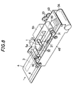
- Fig. 8 is a perspective view showing main portions of the whole of the embodiment as seen from the rear.
- the magnetic card 4 is configured in the same manner as that shown in Fig. 1 and hence duplication of description is omitted.
- a flat permanent magnet 10 in which a V-groove is formed is attached by an adhesive to one end face of a holder which has a slit la and which is formed into a U-like shape.
- the holder is made of plastics or the like.
- a rectangular permanent magnet 11 is embedded into the holder.
- the permanent magnets 10 and 11 are disposed in such a manner that the N- and S-poles are aligned in the card conveying direction.
- the permanent magnet 11 produces a magnetic field which is substantially vertical to the card conveying direction
- the permanent magnet 10 produces a magnetic field which is substantially parallel to the card conveying direction.
- the thus configured erasing head 1 is fixed to the magnetic shield 5a which has a shape configured by three faces of a rectangular parallelopiped shape and in which a slit 12 is formed so as to coincide with the slit 1a.
- a partial gear 13 having a support shaft 13a is integrally attached to the magnetic shield 5a.
- conveying rollers 30 and 31, etc. are attached to the side walls of a chassis 40 so as to function as a card conveying mechanism.
- the conveying rollers 30 and 31 are embraced by an endless belt 32.
- the one conveying roller 31 is driven by a motor 34 via a gear train 33.
- the erasing head 1 is rotatably attached to one of the side walls of the chassis 40.
- the partial gear 13 of the erasing head 1 meshes with a drive gear 14 which is driven by a motor or the like (not shown).
- the erasing head 1 can be angularly displaced about the support shaft 13a of the partial gear 13.
- the magnetic shield 5b defines a space for housing the erasing head 1.
- a recording head 20 in which many electromagnetic coils for producing a spot-like magnetic field are formed is disposed so as to magnetically print visible information on the magnetic display sheet 3 of the magnetic card 4.
- a recording head 21 which records invisible information is disposed at a position corresponding to the magnetic stripe 6 of the magnetic card 4.
- the erasing head 1 When the magnetic display sheet 3 is to be erased, the erasing head 1 is angularly displaced about the support shaft 13a of the partial gear 13 and protrudes into the convey path. Then, the erasing head 1 is positioned so that the conveyed magnetic card 4 passes through the slits 12 and la. When the conveyed magnetic card 4 passes through the slit 12 of the erasing head 1 under this state, black is once written into the whole of the magnetic display sheet 3 by the vertical magnetic field of the permanent magnet 11 of the erasing head 1. Thereafter, the visible information recorded on the magnetic display sheet 3 is erased by the parallel magnetic field of the permanent magnet 10 of the erasing head 1.
- the erasing head 1 is angularly displaced in the direction of the arrow A, namely, in the direction parallel to the card conveying plane, so as to be retracted from the card convey path and then housed in the magnetic shield 5b attached to the chassis 40. Under this state, the magnetic shields 5a and 5b are magnetically joined together so as to block the magnetic field produced by the erasing head 1. As a result, the magnetic fields produced by the permanent magnets 10 and 11 cannot reach the card path, and the magnetic fields are largely attenuated to an extent that the magnetic field in the card path leaves the magnetic display sheet 3 substantially unaffected to any practical extent.
- the use of the magnetic shield can shorten the moving distance of the erasing head 1, with the result that the apparatus can be miniaturised and the degree of freedom of the design is increased.
- the invention provides magnetic display erasing apparatus that has an erasing head and a shield, the head and the shield being operable for relative movement between a first position in an erasing mode of the apparatus in which the erasing head is operable to produce a magnetic field which erases information in a magnetic display arranged in an erasing position relative to the head, and a second position in a non-erasing mode of the apparatus in which the shield is arranged to weaken the magnetic field such that the said information in the magnetic display is substantially unaffected.
Landscapes
- Engineering & Computer Science (AREA)
- Physics & Mathematics (AREA)
- General Physics & Mathematics (AREA)
- Theoretical Computer Science (AREA)
- Artificial Intelligence (AREA)
- Computer Vision & Pattern Recognition (AREA)
- Electrochromic Elements, Electrophoresis, Or Variable Reflection Or Absorption Elements (AREA)
- Credit Cards Or The Like (AREA)
Applications Claiming Priority (2)
| Application Number | Priority Date | Filing Date | Title |
|---|---|---|---|
| JP270263/95 | 1995-10-18 | ||
| JP7270263A JPH09114941A (ja) | 1995-10-18 | 1995-10-18 | 磁気表示消去装置 |
Publications (2)
| Publication Number | Publication Date |
|---|---|
| EP0769752A2 true EP0769752A2 (de) | 1997-04-23 |
| EP0769752A3 EP0769752A3 (de) | 1999-04-07 |
Family
ID=17483822
Family Applications (1)
| Application Number | Title | Priority Date | Filing Date |
|---|---|---|---|
| EP96307591A Withdrawn EP0769752A3 (de) | 1995-10-18 | 1996-10-18 | Löschgerät für magnetische Anzeige |
Country Status (4)
| Country | Link |
|---|---|
| US (1) | US5787619A (de) |
| EP (1) | EP0769752A3 (de) |
| JP (1) | JPH09114941A (de) |
| KR (1) | KR100231476B1 (de) |
Cited By (1)
| Publication number | Priority date | Publication date | Assignee | Title |
|---|---|---|---|---|
| GB2453918A (en) * | 2007-06-29 | 2009-04-29 | Paluku Lusi | Erasing magnetically held information |
Families Citing this family (9)
| Publication number | Priority date | Publication date | Assignee | Title |
|---|---|---|---|---|
| JP3631540B2 (ja) * | 1995-11-28 | 2005-03-23 | スター精密株式会社 | 磁気表示消去装置 |
| US6731491B2 (en) * | 2001-06-15 | 2004-05-04 | Data Security, Inc. | Bulk degausser with fixed arrays of magnet poles |
| US7164569B1 (en) | 2004-06-30 | 2007-01-16 | Data Security, Inc. | Mechanism for automated permanent magnet degaussing |
| US20060018075A1 (en) * | 2004-07-23 | 2006-01-26 | Data Security, Inc. | Permanent magnet bulk degausser |
| EP1988545B1 (de) * | 2006-02-17 | 2012-04-11 | Nidec Sankyo Corporation | Medium-verarbeitende vorrichtung und an diese anpassbarer magnetkopf |
| US7715166B2 (en) * | 2006-07-14 | 2010-05-11 | Data Security, Inc. | Method and reciprocating apparatus for permanent magnet erasure of magnetic storage media |
| US7701656B2 (en) * | 2006-07-14 | 2010-04-20 | Data Security, Inc. | Method and apparatus for permanent magnet erasure of magnetic storage media |
| US20090284890A1 (en) * | 2008-05-16 | 2009-11-19 | Thiel Leroy D | Mechanism and Method for Permanent Magnet Degaussing |
| US8134435B2 (en) * | 2008-09-29 | 2012-03-13 | Rockwell Automation Technologies, Inc. | Flux mitigation |
Family Cites Families (7)
| Publication number | Priority date | Publication date | Assignee | Title |
|---|---|---|---|---|
| JPS5645060Y2 (de) * | 1976-09-01 | 1981-10-21 | ||
| JPS5429895A (en) * | 1977-08-11 | 1979-03-06 | Inoue Japax Res Inc | Carbon material |
| US4675476A (en) * | 1984-10-11 | 1987-06-23 | Nec Corporation | Magnetophoresis type display and graphic input/output device using the same |
| US5317340A (en) * | 1990-08-23 | 1994-05-31 | Mody Hemant K | Method and device for erasing and writing on magnetic recording media suitable for direct viewing |
| US5359183A (en) * | 1992-04-06 | 1994-10-25 | Rafael Skodlar | Payment card with display |
| JP3035071B2 (ja) * | 1992-05-01 | 2000-04-17 | 日本信号株式会社 | 磁気記録媒体の水平磁化装置 |
| JPH06168369A (ja) * | 1992-11-30 | 1994-06-14 | Star Micronics Co Ltd | 磁気表示カードの磁気表示消去装置 |
-
1995
- 1995-10-18 JP JP7270263A patent/JPH09114941A/ja active Pending
-
1996
- 1996-10-17 KR KR1019960046591A patent/KR100231476B1/ko not_active Expired - Fee Related
- 1996-10-18 US US08/733,781 patent/US5787619A/en not_active Expired - Fee Related
- 1996-10-18 EP EP96307591A patent/EP0769752A3/de not_active Withdrawn
Non-Patent Citations (1)
| Title |
|---|
| None |
Cited By (1)
| Publication number | Priority date | Publication date | Assignee | Title |
|---|---|---|---|---|
| GB2453918A (en) * | 2007-06-29 | 2009-04-29 | Paluku Lusi | Erasing magnetically held information |
Also Published As
| Publication number | Publication date |
|---|---|
| EP0769752A3 (de) | 1999-04-07 |
| US5787619A (en) | 1998-08-04 |
| KR100231476B1 (en) | 1999-11-15 |
| JPH09114941A (ja) | 1997-05-02 |
Similar Documents
| Publication | Publication Date | Title |
|---|---|---|
| US5359183A (en) | Payment card with display | |
| US5787619A (en) | Magnetic display erasing apparatus | |
| EP0093410A2 (de) | Gerät zum Abtasten eines Magnetstreifens auf einem Datenträger | |
| EP0242126A2 (de) | IC-Karte und zugehöriges System | |
| EP0317201A2 (de) | Tragbares Speichermedium | |
| CN102725766A (zh) | 读卡机 | |
| CA2228615A1 (en) | Secure credit card | |
| US4459679A (en) | Magnetic bubble memory device cassette | |
| HK1009613A (en) | Magnetic display erasing apparatus | |
| JPH0678037B2 (ja) | 認証識別媒体の認証装置 | |
| US7891568B2 (en) | Media processing device and magnetic head applicable to it | |
| WO2004034837A1 (en) | Device for storing and protecting a data carrier | |
| JPH09114938A (ja) | 磁気表示書込装置および磁気表示消去装置 | |
| JP2005129183A (ja) | 記録媒体、記録媒体の判別方法及びカードリーダ | |
| JPH06168369A (ja) | 磁気表示カードの磁気表示消去装置 | |
| JP3111455U (ja) | 磁気テープ担持体用収容具 | |
| JP2005100150A (ja) | 磁気表示部を有したカード | |
| EP0528927B1 (de) | Kartenleser | |
| JPH043283A (ja) | 磁気記録カード | |
| JPH02212194A (ja) | カード表示方法 | |
| JPH0516129Y2 (de) | ||
| JP2000187807A (ja) | マルチ磁気ヘッド | |
| JPH0737027A (ja) | 磁性コード印刷物、その読取り方法および装置 | |
| JPH06286368A (ja) | 記録担体カードとその真偽判定装置 | |
| JPH07182606A (ja) | 磁気ヘッド装置 |
Legal Events
| Date | Code | Title | Description |
|---|---|---|---|
| PUAI | Public reference made under article 153(3) epc to a published international application that has entered the european phase |
Free format text: ORIGINAL CODE: 0009012 |
|
| AK | Designated contracting states |
Kind code of ref document: A2 Designated state(s): DE GB |
|
| PUAL | Search report despatched |
Free format text: ORIGINAL CODE: 0009013 |
|
| AK | Designated contracting states |
Kind code of ref document: A3 Designated state(s): DE GB |
|
| 17P | Request for examination filed |
Effective date: 19990707 |
|
| GRAH | Despatch of communication of intention to grant a patent |
Free format text: ORIGINAL CODE: EPIDOS IGRA |
|
| STAA | Information on the status of an ep patent application or granted ep patent |
Free format text: STATUS: THE APPLICATION IS DEEMED TO BE WITHDRAWN |
|
| 18D | Application deemed to be withdrawn |
Effective date: 20030325 |
|
| REG | Reference to a national code |
Ref country code: HK Ref legal event code: WD Ref document number: 1009613 Country of ref document: HK |