EP0769854A1 - System zur richtigen Binärformatdekodierung eines auf einer magnetischen Spur gespeicherten magnetischen Codes - Google Patents
System zur richtigen Binärformatdekodierung eines auf einer magnetischen Spur gespeicherten magnetischen Codes Download PDFInfo
- Publication number
- EP0769854A1 EP0769854A1 EP96402208A EP96402208A EP0769854A1 EP 0769854 A1 EP0769854 A1 EP 0769854A1 EP 96402208 A EP96402208 A EP 96402208A EP 96402208 A EP96402208 A EP 96402208A EP 0769854 A1 EP0769854 A1 EP 0769854A1
- Authority
- EP
- European Patent Office
- Prior art keywords
- bits
- magnetic
- length
- message
- code
- Prior art date
- Legal status (The legal status is an assumption and is not a legal conclusion. Google has not performed a legal analysis and makes no representation as to the accuracy of the status listed.)
- Granted
Links
Images
Classifications
-
- G—PHYSICS
- G06—COMPUTING OR CALCULATING; COUNTING
- G06K—GRAPHICAL DATA READING; PRESENTATION OF DATA; RECORD CARRIERS; HANDLING RECORD CARRIERS
- G06K7/00—Methods or arrangements for sensing record carriers, e.g. for reading patterns
- G06K7/08—Methods or arrangements for sensing record carriers, e.g. for reading patterns by means detecting the change of an electrostatic or magnetic field, e.g. by detecting change of capacitance between electrodes
- G06K7/082—Methods or arrangements for sensing record carriers, e.g. for reading patterns by means detecting the change of an electrostatic or magnetic field, e.g. by detecting change of capacitance between electrodes using inductive or magnetic sensors
- G06K7/083—Methods or arrangements for sensing record carriers, e.g. for reading patterns by means detecting the change of an electrostatic or magnetic field, e.g. by detecting change of capacitance between electrodes using inductive or magnetic sensors inductive
- G06K7/084—Methods or arrangements for sensing record carriers, e.g. for reading patterns by means detecting the change of an electrostatic or magnetic field, e.g. by detecting change of capacitance between electrodes using inductive or magnetic sensors inductive sensing magnetic material by relative movement detecting flux changes without altering its magnetised state
-
- G—PHYSICS
- G11—INFORMATION STORAGE
- G11B—INFORMATION STORAGE BASED ON RELATIVE MOVEMENT BETWEEN RECORD CARRIER AND TRANSDUCER
- G11B20/00—Signal processing not specific to the method of recording or reproducing; Circuits therefor
- G11B20/10—Digital recording or reproducing
- G11B20/18—Error detection or correction; Testing, e.g. of drop-outs
- G11B20/1833—Error detection or correction; Testing, e.g. of drop-outs by adding special lists or symbols to the coded information
-
- H—ELECTRICITY
- H03—ELECTRONIC CIRCUITRY
- H03M—CODING; DECODING; CODE CONVERSION IN GENERAL
- H03M13/00—Coding, decoding or code conversion, for error detection or error correction; Coding theory basic assumptions; Coding bounds; Error probability evaluation methods; Channel models; Simulation or testing of codes
- H03M13/03—Error detection or forward error correction by redundancy in data representation, i.e. code words containing more digits than the source words
- H03M13/05—Error detection or forward error correction by redundancy in data representation, i.e. code words containing more digits than the source words using block codes, i.e. a predetermined number of check bits joined to a predetermined number of information bits
- H03M13/09—Error detection only, e.g. using cyclic redundancy check [CRC] codes or single parity bit
Definitions
- Magnetic recordings on media such as tickets, cards, etc. are subject, due to public use, to deterioration and alteration of the magnetically recorded messages. This is particularly the case for flexible supports which sometimes undergo folds most often resulting in the alteration of the magnetic material and therefore the alteration of the recorded information.
- a known technique for overcoming such a drawback consists in repeating the recorded message a second time. It is however necessary to provide the two messages with additional information making it possible to detect in the event of an error on one of the messages, and only on one, which is false in order to retain the other.
- This technique has the disadvantage of doubling, for a given linear density of bits, the length necessary to record a message, or of significantly limiting the possible length of a message on a magnetic strip medium of given length.
- the object of the present invention is to overcome such a drawback and proposes a system which makes it possible to reconstruct a missing or erroneous block of information provided that such a block called "erroneous packet" of bits is unique and localizable. Otherwise, the invention makes it possible to detect that the message is false, but not to correct it.
- the principle of the invention is to use a cyclic redundancy code called CRC which is a known redundancy code having particular properties, associated with a particular technique, applicable to magnetic recordings, for error localization.
- CRC cyclic redundancy code
- redundancy codes consists in supplementing a block of binary information with a set of control bits defined by a law, or application, on the bits of useful information.
- Error detection consists in checking whether the present message of n bits is indeed a word of the redundancy code by applying to the m useful message bits the law of generation of the k control bits and in comparing these k bits found by application of the law to those actually present in the word read by n bits.
- redundancy codes there are the cyclic redundancy codes.
- a cyclic redundancy code is a particular redundancy code of course meeting the general definition given above of redundancy codes, but having the remarkable characteristic property that any circular permutation of a word of the code also constitutes a word of the code.
- This remarkable property makes it possible to correct, if it can be located, a packet error, that is to say an error constituted by a continuous series of bits. Indeed, this remarkable property means that there is no pair of code words having, outside of any packet of k successive bits (k being the number of bits of the control structure), the same structure. This therefore makes it possible to correct an error of a bit packet of length ⁇ k, with certainty, if however it can be located.
- the degree n i of consecutive terms decreases by one from left to right from the degree n - 1 to reach degree 0.
- the degree n i of a term is therefore representative of the location of the bit it represents in the structure of n bits.
- the coefficient a i of a term is equal to 0 or 1 depending on the value 0 or 1 of the bit represented by this term.
- a word of n bit belongs to a cyclic redundancy code having k bits of control structure if the polynomial representing these n bits is divisible, in algebra modulo 2, without restraint, by a generator polynomial G (x) of degree k .
- This generator polynomial G (x) of degree k must also be a divisor of the polynomial x n -1.
- n bits are preceded in logic by n 'null bits.
- a word of the cyclic redundancy code comprises n '+ n bits and this must be taken into account in the circular permutations.
- the remainder is a polynomial of degree k - 1, we mean that it represents k bits but it may be that, in fact, the representative polynomial is of lower degree for example of degree k - 2, that means say that the term degree k - 1 is absent and therefore represents a 0.
- the polynomial x 3 + x + 1 is therefore a G (x) generator of a code C (7, 4).
- 0001011 this is a word of the cyclic redundancy code C (7, 4) and in this word, the k bits 011 constitute the control structure of the useful message 0001.
- the location of the erroneous packet is only carried out by seeking its start and it is assumed that the packet is erroneous on k bits.
- these m4 bits are logical 0s, but this is not necessary.
- the order of recording of the n bits on the magnetic track is as follows: m1, m2, k, m3.
- adaptation bits m4 when there are adaptation bits m4, they are placed before the bits m1, whether they are magnetically recorded or only logically present.
- the law of generation of the cyclic redundancy code C (n, n - k) is a generator polynomial G (x) of degree k divisor of the polynomial x n - 1 in the algebra modulo 2 without detention.
- the invention therefore consists in using a cyclic redundancy code CRC associated with an error localization technique.
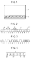
- Figure 1 shows a magnetic title
- FIG. 2 represents the coding of the magnetic stripe.
- FIG. 3 represents the decoded signal from the reading of the track.
- G (x) x 3 + x + 1 which represents 1011.
- a circular permutation will be carried out so as to place the three control bits 001 between m2 and m3.
- FIG. 1 shows a card 1 carrying a magnetic strip 2.
- FIG. 2 represents the magnetic coding of the magnetic track 2.
- FIG. 3 represents the signal resulting from the reading of the magnetic strip.
- Figure 4 shows the decoded message
- FIG. 3 shows the signal resulting from the reading of the magnetic strip 2.
- Figure 4 shows the binary message broken down into its parts: m1 message start bits, m2 useful message bits, k control bits and m3 message end bits.
- the duration between two magnetic transitions is therefore proportional to the length l 1 or l 2 .
- the packet of non-decoded bits is logically placed at the end of the message by giving a zero value to these bits, and the law G (x) is applied to find the value of these bits. It only remains to place these bits in the right place by circular permutation.
- the correct word is then searched for by a likelihood criterion. Here it is the first.
- G (x) exists, it is x 3 + x + 1 ⁇ 1011.
- the invention does not allow, taking into account the adopted localization technique, to correct an error in which there is no anomaly of the magnetic structure by which then, the error cannot be located. This is the case if a 0 becomes a 1 or vice versa.
Landscapes
- Engineering & Computer Science (AREA)
- Physics & Mathematics (AREA)
- Theoretical Computer Science (AREA)
- Signal Processing (AREA)
- Artificial Intelligence (AREA)
- Computer Vision & Pattern Recognition (AREA)
- General Physics & Mathematics (AREA)
- Probability & Statistics with Applications (AREA)
- Error Detection And Correction (AREA)
- Signal Processing For Digital Recording And Reproducing (AREA)
Applications Claiming Priority (2)
| Application Number | Priority Date | Filing Date | Title |
|---|---|---|---|
| FR9512368 | 1995-10-20 | ||
| FR9512368A FR2740280B1 (fr) | 1995-10-20 | 1995-10-20 | Systeme permettant un decodage correct, sous forme d'un message binaire, d'un code magnetique enregistre sur une piste magnetique |
Publications (2)
| Publication Number | Publication Date |
|---|---|
| EP0769854A1 true EP0769854A1 (de) | 1997-04-23 |
| EP0769854B1 EP0769854B1 (de) | 2002-02-20 |
Family
ID=9483752
Family Applications (1)
| Application Number | Title | Priority Date | Filing Date |
|---|---|---|---|
| EP96402208A Expired - Lifetime EP0769854B1 (de) | 1995-10-20 | 1996-10-16 | System zur richtigen Binärformatdekodierung eines auf einer magnetischen Spur gespeicherten magnetischen Codes |
Country Status (5)
| Country | Link |
|---|---|
| US (1) | US5748649A (de) |
| EP (1) | EP0769854B1 (de) |
| DE (1) | DE69619329T2 (de) |
| ES (1) | ES2173261T3 (de) |
| FR (1) | FR2740280B1 (de) |
Families Citing this family (5)
| Publication number | Priority date | Publication date | Assignee | Title |
|---|---|---|---|---|
| US6128528A (en) * | 1999-03-18 | 2000-10-03 | Medtronics, Inc. | Error code calculations for data stored in an implantable medical device |
| US6526530B1 (en) * | 1999-12-22 | 2003-02-25 | Marvell International, Ltd. | Method and apparatus for encoding data incorporating check bits and maximum transition run constraint |
| JP2009094605A (ja) * | 2007-10-04 | 2009-04-30 | Oki Semiconductor Co Ltd | 符号誤り検出装置および誤り検出符号生成装置 |
| GB2482735A (en) * | 2010-08-13 | 2012-02-15 | Alexandru Ion Sovu | Data recovery for a magnetic stripe reader |
| JP7135657B2 (ja) | 2018-09-25 | 2022-09-13 | 株式会社デンソー | 車両制御装置 |
Citations (5)
| Publication number | Priority date | Publication date | Assignee | Title |
|---|---|---|---|---|
| JPS62271261A (ja) * | 1986-05-20 | 1987-11-25 | Sanyo Electric Co Ltd | Pcmオ−デイオのマルチトラツク記録再生方法 |
| JPS63126080A (ja) * | 1986-11-14 | 1988-05-30 | Fujitsu Ltd | 記録媒体読取装置 |
| JPS6444627A (en) * | 1987-08-12 | 1989-02-17 | Fujitsu Ltd | Data correction system |
| EP0407101A2 (de) * | 1989-06-28 | 1991-01-09 | Digital Equipment Corporation | Fehlererkennungs- und Fehlerkorrektursystem für Burstfehler |
| US5251077A (en) * | 1990-06-15 | 1993-10-05 | Teac Corporation | Method of reading digital data on magnetic tape |
Family Cites Families (1)
| Publication number | Priority date | Publication date | Assignee | Title |
|---|---|---|---|---|
| US5390195A (en) * | 1992-04-03 | 1995-02-14 | Ampex Corporation | Miller-squared decoder with erasure flag output |
-
1995
- 1995-10-20 FR FR9512368A patent/FR2740280B1/fr not_active Expired - Fee Related
-
1996
- 1996-10-16 EP EP96402208A patent/EP0769854B1/de not_active Expired - Lifetime
- 1996-10-16 ES ES96402208T patent/ES2173261T3/es not_active Expired - Lifetime
- 1996-10-16 DE DE69619329T patent/DE69619329T2/de not_active Expired - Fee Related
- 1996-10-18 US US08/733,452 patent/US5748649A/en not_active Expired - Fee Related
Patent Citations (5)
| Publication number | Priority date | Publication date | Assignee | Title |
|---|---|---|---|---|
| JPS62271261A (ja) * | 1986-05-20 | 1987-11-25 | Sanyo Electric Co Ltd | Pcmオ−デイオのマルチトラツク記録再生方法 |
| JPS63126080A (ja) * | 1986-11-14 | 1988-05-30 | Fujitsu Ltd | 記録媒体読取装置 |
| JPS6444627A (en) * | 1987-08-12 | 1989-02-17 | Fujitsu Ltd | Data correction system |
| EP0407101A2 (de) * | 1989-06-28 | 1991-01-09 | Digital Equipment Corporation | Fehlererkennungs- und Fehlerkorrektursystem für Burstfehler |
| US5251077A (en) * | 1990-06-15 | 1993-10-05 | Teac Corporation | Method of reading digital data on magnetic tape |
Non-Patent Citations (3)
| Title |
|---|
| PATENT ABSTRACTS OF JAPAN vol. 12, no. 154 (P - 700) 12 May 1988 (1988-05-12) * |
| PATENT ABSTRACTS OF JAPAN vol. 12, no. 380 (P - 769) 12 October 1988 (1988-10-12) * |
| PATENT ABSTRACTS OF JAPAN vol. 13, no. 243 (P - 768) 7 June 1989 (1989-06-07) * |
Also Published As
| Publication number | Publication date |
|---|---|
| FR2740280A1 (fr) | 1997-04-25 |
| EP0769854B1 (de) | 2002-02-20 |
| DE69619329D1 (de) | 2002-03-28 |
| ES2173261T3 (es) | 2002-10-16 |
| DE69619329T2 (de) | 2002-10-24 |
| US5748649A (en) | 1998-05-05 |
| FR2740280B1 (fr) | 1997-11-21 |
Similar Documents
| Publication | Publication Date | Title |
|---|---|---|
| EP0484259B1 (de) | Binärkodierungsverfahren mit gleichmässiger Umschaltung-Verteilung der binären Elemente und Inkrementierungs-Dekrementierungsverfahren dafür | |
| EP0436251B1 (de) | System zur Kodierung/Dekodierung von digitalen Signalen zur Übertragung und/oder Speicherung | |
| EP0078218B1 (de) | Identifizierungsverfahren für unerlaubte Schallaufzeichnungen und Kopiergerät zur Durchführung des Verfahrens | |
| EP0995272B1 (de) | Iterative dekodierung von produktkoden | |
| EP0654910A1 (de) | Verfahren zur Detektion von durch verkettete Blockcodes verarbeitete Informationsbits | |
| FR2504755A1 (fr) | Procede et appareil de codage d'un signal numerique sans retour a zero inverse avec une faible composante continue | |
| EP0329533B1 (de) | Kodierungs- und Dekodierungsverfahren variabler Länge, Kodierungs- und Dekodierungsvorrichtung zur Ausführung dieses Verfahrens | |
| EP0204635B1 (de) | Verfahren zur Übertragung von digitaler Information in Wörterblöcken | |
| EP0553050B1 (de) | Verfahren zur Maximalwahrscheinlichkeitsdekodierung mit unterabgetastetem Dekodierungstrellis und entsprechende Dekodierungsvorrichtung | |
| EP0769854B1 (de) | System zur richtigen Binärformatdekodierung eines auf einer magnetischen Spur gespeicherten magnetischen Codes | |
| EP0066512A1 (de) | Kodierungsverfahren für binäre Daten und Anwendung des Verfahrens in einem Magnetband-Transfer-System für ein digitales Videosignal | |
| US6347390B1 (en) | Data encoding method and device, data decoding method and device, and data supply medium | |
| EP0549412A1 (de) | Zeittaktschaltung für Lesegerät für sequentielle Daten | |
| EP0012880A1 (de) | Verfahren zum Dekodieren phasenkodierter, frequenzmoduliert kodierter oder in modifizierter Frequenzmodulation kodierter Binärdaten | |
| FR2863794A1 (fr) | Procedes et dispositifs de localisation d'erreurs pour les codes de geometrie algebrique | |
| CH659555A5 (fr) | Procede et dispositif de codage d'une information digitale codee sous forme binaire. | |
| EP0604311A1 (de) | Dateienverwaltungsverfahren, Aufzeichnungsmedium und Rechnersystem dafür | |
| EP0982866B1 (de) | Verfahren zur Faltungskodierung und Uebertragung von digitalen Datenpaketen, Gerät und Verfahren zur entsprechenden Dekodierung | |
| FR2891419A1 (fr) | Decodage d'une pluralite de flux d'informations codees selon un algorithme de codage par blocs. | |
| JP3658395B2 (ja) | 信号復調装置及び方法 | |
| EP0715430B1 (de) | Übertragungssystem mit fehlerkorrigierendem Paritätskode | |
| EP0772303B1 (de) | Viterbi-Detektor mit verkleinertem Pfadspeicher | |
| EP0438340A1 (de) | Verfahren und Vorrichtung zur Datenkompression | |
| JP3991348B2 (ja) | 符号化装置および方法、復号装置および方法、並びに記録媒体 | |
| EP0211757A1 (de) | Verfahren zur Basisband-Modulation eines Datensignals, Modulationsgerät und Demodulationsgerät dafür |
Legal Events
| Date | Code | Title | Description |
|---|---|---|---|
| PUAI | Public reference made under article 153(3) epc to a published international application that has entered the european phase |
Free format text: ORIGINAL CODE: 0009012 |
|
| AK | Designated contracting states |
Kind code of ref document: A1 Designated state(s): DE ES FR GB IT |
|
| 17P | Request for examination filed |
Effective date: 19970822 |
|
| GRAG | Despatch of communication of intention to grant |
Free format text: ORIGINAL CODE: EPIDOS AGRA |
|
| 17Q | First examination report despatched |
Effective date: 20010430 |
|
| GRAG | Despatch of communication of intention to grant |
Free format text: ORIGINAL CODE: EPIDOS AGRA |
|
| GRAH | Despatch of communication of intention to grant a patent |
Free format text: ORIGINAL CODE: EPIDOS IGRA |
|
| GRAH | Despatch of communication of intention to grant a patent |
Free format text: ORIGINAL CODE: EPIDOS IGRA |
|
| REG | Reference to a national code |
Ref country code: GB Ref legal event code: IF02 |
|
| GRAA | (expected) grant |
Free format text: ORIGINAL CODE: 0009210 |
|
| AK | Designated contracting states |
Kind code of ref document: B1 Designated state(s): DE ES FR GB IT |
|
| REF | Corresponds to: |
Ref document number: 69619329 Country of ref document: DE Date of ref document: 20020328 |
|
| RAP2 | Party data changed (patent owner data changed or rights of a patent transferred) |
Owner name: THALES E-TRANSACTIONS S.A. |
|
| RAP2 | Party data changed (patent owner data changed or rights of a patent transferred) |
Owner name: THALES E-TRANSACTIONS CGA S.A. |
|
| GBT | Gb: translation of ep patent filed (gb section 77(6)(a)/1977) |
Effective date: 20020614 |
|
| REG | Reference to a national code |
Ref country code: ES Ref legal event code: FG2A Ref document number: 2173261 Country of ref document: ES Kind code of ref document: T3 |
|
| PLBE | No opposition filed within time limit |
Free format text: ORIGINAL CODE: 0009261 |
|
| STAA | Information on the status of an ep patent application or granted ep patent |
Free format text: STATUS: NO OPPOSITION FILED WITHIN TIME LIMIT |
|
| 26N | No opposition filed |
Effective date: 20021121 |
|
| PGFP | Annual fee paid to national office [announced via postgrant information from national office to epo] |
Ref country code: ES Payment date: 20071120 Year of fee payment: 12 Ref country code: DE Payment date: 20071011 Year of fee payment: 12 |
|
| PGFP | Annual fee paid to national office [announced via postgrant information from national office to epo] |
Ref country code: IT Payment date: 20071027 Year of fee payment: 12 |
|
| PGFP | Annual fee paid to national office [announced via postgrant information from national office to epo] |
Ref country code: GB Payment date: 20071010 Year of fee payment: 12 Ref country code: FR Payment date: 20071009 Year of fee payment: 12 |
|
| GBPC | Gb: european patent ceased through non-payment of renewal fee |
Effective date: 20081016 |
|
| REG | Reference to a national code |
Ref country code: FR Ref legal event code: ST Effective date: 20090630 |
|
| PG25 | Lapsed in a contracting state [announced via postgrant information from national office to epo] |
Ref country code: IT Free format text: LAPSE BECAUSE OF NON-PAYMENT OF DUE FEES Effective date: 20081016 Ref country code: DE Free format text: LAPSE BECAUSE OF NON-PAYMENT OF DUE FEES Effective date: 20090501 |
|
| PG25 | Lapsed in a contracting state [announced via postgrant information from national office to epo] |
Ref country code: FR Free format text: LAPSE BECAUSE OF NON-PAYMENT OF DUE FEES Effective date: 20081031 |
|
| PG25 | Lapsed in a contracting state [announced via postgrant information from national office to epo] |
Ref country code: GB Free format text: LAPSE BECAUSE OF NON-PAYMENT OF DUE FEES Effective date: 20081016 |
|
| REG | Reference to a national code |
Ref country code: ES Ref legal event code: FD2A Effective date: 20081017 |
|
| PG25 | Lapsed in a contracting state [announced via postgrant information from national office to epo] |
Ref country code: ES Free format text: LAPSE BECAUSE OF NON-PAYMENT OF DUE FEES Effective date: 20081017 |