EP0770154B1 - Procede de moulage utilisant des amas de fibres - Google Patents
Procede de moulage utilisant des amas de fibres Download PDFInfo
- Publication number
- EP0770154B1 EP0770154B1 EP95926624A EP95926624A EP0770154B1 EP 0770154 B1 EP0770154 B1 EP 0770154B1 EP 95926624 A EP95926624 A EP 95926624A EP 95926624 A EP95926624 A EP 95926624A EP 0770154 B1 EP0770154 B1 EP 0770154B1
- Authority
- EP
- European Patent Office
- Prior art keywords
- mold
- automated process
- clusters
- fiber clusters
- loading
- Prior art date
- Legal status (The legal status is an assumption and is not a legal conclusion. Google has not performed a legal analysis and makes no representation as to the accuracy of the status listed.)
- Expired - Lifetime
Links
- 239000000835 fiber Substances 0.000 title claims abstract description 74
- 238000000034 method Methods 0.000 title claims abstract description 51
- 238000000465 moulding Methods 0.000 title claims abstract description 19
- 238000010438 heat treatment Methods 0.000 claims abstract description 19
- 229920000728 polyester Polymers 0.000 claims abstract description 16
- 238000001816 cooling Methods 0.000 claims abstract description 14
- 239000000853 adhesive Substances 0.000 claims abstract description 12
- 230000001070 adhesive effect Effects 0.000 claims abstract description 12
- 238000005538 encapsulation Methods 0.000 claims description 12
- 239000000463 material Substances 0.000 claims description 11
- 239000011230 binding agent Substances 0.000 claims description 9
- 229920000642 polymer Polymers 0.000 claims description 7
- 239000010985 leather Substances 0.000 claims description 6
- 229920001169 thermoplastic Polymers 0.000 claims description 5
- 239000004416 thermosoftening plastic Substances 0.000 claims description 5
- 239000011248 coating agent Substances 0.000 claims description 3
- 238000000576 coating method Methods 0.000 claims description 3
- 238000009434 installation Methods 0.000 claims description 3
- 238000004064 recycling Methods 0.000 claims description 3
- 238000002844 melting Methods 0.000 claims description 2
- 230000008018 melting Effects 0.000 claims description 2
- 238000005507 spraying Methods 0.000 claims 1
- 230000008901 benefit Effects 0.000 description 6
- 239000004744 fabric Substances 0.000 description 4
- 229910052751 metal Inorganic materials 0.000 description 4
- 239000002184 metal Substances 0.000 description 4
- 239000002313 adhesive film Substances 0.000 description 3
- 150000001336 alkenes Chemical class 0.000 description 3
- 229920005830 Polyurethane Foam Polymers 0.000 description 2
- 239000012790 adhesive layer Substances 0.000 description 2
- 229910052782 aluminium Inorganic materials 0.000 description 2
- XAGFODPZIPBFFR-UHFFFAOYSA-N aluminium Chemical compound [Al] XAGFODPZIPBFFR-UHFFFAOYSA-N 0.000 description 2
- 239000003795 chemical substances by application Substances 0.000 description 2
- 230000005294 ferromagnetic effect Effects 0.000 description 2
- 238000005429 filling process Methods 0.000 description 2
- 239000006260 foam Substances 0.000 description 2
- 239000010410 layer Substances 0.000 description 2
- 238000004519 manufacturing process Methods 0.000 description 2
- 239000000155 melt Substances 0.000 description 2
- JRZJOMJEPLMPRA-UHFFFAOYSA-N olefin Natural products CCCCCCCC=C JRZJOMJEPLMPRA-UHFFFAOYSA-N 0.000 description 2
- -1 polyethylene Polymers 0.000 description 2
- 239000011496 polyurethane foam Substances 0.000 description 2
- 238000002360 preparation method Methods 0.000 description 2
- 239000007921 spray Substances 0.000 description 2
- OKTJSMMVPCPJKN-UHFFFAOYSA-N Carbon Chemical compound [C] OKTJSMMVPCPJKN-UHFFFAOYSA-N 0.000 description 1
- 229910000975 Carbon steel Inorganic materials 0.000 description 1
- 239000004698 Polyethylene Substances 0.000 description 1
- 239000004772 Sontara Substances 0.000 description 1
- 230000001133 acceleration Effects 0.000 description 1
- 238000004873 anchoring Methods 0.000 description 1
- 238000010923 batch production Methods 0.000 description 1
- 239000010962 carbon steel Substances 0.000 description 1
- 230000005465 channeling Effects 0.000 description 1
- 230000006835 compression Effects 0.000 description 1
- 238000007906 compression Methods 0.000 description 1
- 238000010276 construction Methods 0.000 description 1
- 238000010924 continuous production Methods 0.000 description 1
- 230000001419 dependent effect Effects 0.000 description 1
- 238000009826 distribution Methods 0.000 description 1
- 230000000694 effects Effects 0.000 description 1
- 230000008030 elimination Effects 0.000 description 1
- 238000003379 elimination reaction Methods 0.000 description 1
- 239000006261 foam material Substances 0.000 description 1
- 229910021397 glassy carbon Inorganic materials 0.000 description 1
- 230000005484 gravity Effects 0.000 description 1
- 150000002739 metals Chemical class 0.000 description 1
- 238000006140 methanolysis reaction Methods 0.000 description 1
- 238000012544 monitoring process Methods 0.000 description 1
- 239000000178 monomer Substances 0.000 description 1
- 229920000573 polyethylene Polymers 0.000 description 1
- 239000002994 raw material Substances 0.000 description 1
- 230000002787 reinforcement Effects 0.000 description 1
- 239000010935 stainless steel Substances 0.000 description 1
- 229910001220 stainless steel Inorganic materials 0.000 description 1
- 238000003860 storage Methods 0.000 description 1
- 238000009966 trimming Methods 0.000 description 1
- 239000002699 waste material Substances 0.000 description 1
- 238000005303 weighing Methods 0.000 description 1
Images


Classifications
-
- B—PERFORMING OPERATIONS; TRANSPORTING
- B29—WORKING OF PLASTICS; WORKING OF SUBSTANCES IN A PLASTIC STATE IN GENERAL
- B29C—SHAPING OR JOINING OF PLASTICS; SHAPING OF MATERIAL IN A PLASTIC STATE, NOT OTHERWISE PROVIDED FOR; AFTER-TREATMENT OF THE SHAPED PRODUCTS, e.g. REPAIRING
- B29C70/00—Shaping composites, i.e. plastics material comprising reinforcements, fillers or preformed parts, e.g. inserts
- B29C70/04—Shaping composites, i.e. plastics material comprising reinforcements, fillers or preformed parts, e.g. inserts comprising reinforcements only, e.g. self-reinforcing plastics
- B29C70/28—Shaping operations therefor
- B29C70/54—Component parts, details or accessories; Auxiliary operations, e.g. feeding or storage of prepregs or SMC after impregnation or during ageing
- B29C70/542—Placing or positioning the reinforcement in a covering or packaging element before or during moulding, e.g. drawing in a sleeve
-
- B—PERFORMING OPERATIONS; TRANSPORTING
- B29—WORKING OF PLASTICS; WORKING OF SUBSTANCES IN A PLASTIC STATE IN GENERAL
- B29C—SHAPING OR JOINING OF PLASTICS; SHAPING OF MATERIAL IN A PLASTIC STATE, NOT OTHERWISE PROVIDED FOR; AFTER-TREATMENT OF THE SHAPED PRODUCTS, e.g. REPAIRING
- B29C70/00—Shaping composites, i.e. plastics material comprising reinforcements, fillers or preformed parts, e.g. inserts
- B29C70/04—Shaping composites, i.e. plastics material comprising reinforcements, fillers or preformed parts, e.g. inserts comprising reinforcements only, e.g. self-reinforcing plastics
- B29C70/28—Shaping operations therefor
- B29C70/30—Shaping by lay-up, i.e. applying fibres, tape or broadsheet on a mould, former or core; Shaping by spray-up, i.e. spraying of fibres on a mould, former or core
- B29C70/305—Spray-up of reinforcing fibres with or without matrix to form a non-coherent mat in or on a mould
-
- D—TEXTILES; PAPER
- D04—BRAIDING; LACE-MAKING; KNITTING; TRIMMINGS; NON-WOVEN FABRICS
- D04H—MAKING TEXTILE FABRICS, e.g. FROM FIBRES OR FILAMENTARY MATERIAL; FABRICS MADE BY SUCH PROCESSES OR APPARATUS, e.g. FELTS, NON-WOVEN FABRICS; COTTON-WOOL; WADDING ; NON-WOVEN FABRICS FROM STAPLE FIBRES, FILAMENTS OR YARNS, BONDED WITH AT LEAST ONE WEB-LIKE MATERIAL DURING THEIR CONSOLIDATION
- D04H1/00—Non-woven fabrics formed wholly or mainly of staple fibres or like relatively short fibres
- D04H1/02—Cotton wool; Wadding
-
- D—TEXTILES; PAPER
- D04—BRAIDING; LACE-MAKING; KNITTING; TRIMMINGS; NON-WOVEN FABRICS
- D04H—MAKING TEXTILE FABRICS, e.g. FROM FIBRES OR FILAMENTARY MATERIAL; FABRICS MADE BY SUCH PROCESSES OR APPARATUS, e.g. FELTS, NON-WOVEN FABRICS; COTTON-WOOL; WADDING ; NON-WOVEN FABRICS FROM STAPLE FIBRES, FILAMENTS OR YARNS, BONDED WITH AT LEAST ONE WEB-LIKE MATERIAL DURING THEIR CONSOLIDATION
- D04H1/00—Non-woven fabrics formed wholly or mainly of staple fibres or like relatively short fibres
- D04H1/40—Non-woven fabrics formed wholly or mainly of staple fibres or like relatively short fibres from fleeces or layers composed of fibres without existing or potential cohesive properties
- D04H1/54—Non-woven fabrics formed wholly or mainly of staple fibres or like relatively short fibres from fleeces or layers composed of fibres without existing or potential cohesive properties by welding together the fibres, e.g. by partially melting or dissolving
- D04H1/558—Non-woven fabrics formed wholly or mainly of staple fibres or like relatively short fibres from fleeces or layers composed of fibres without existing or potential cohesive properties by welding together the fibres, e.g. by partially melting or dissolving in combination with mechanical or physical treatments other than embossing
-
- B—PERFORMING OPERATIONS; TRANSPORTING
- B29—WORKING OF PLASTICS; WORKING OF SUBSTANCES IN A PLASTIC STATE IN GENERAL
- B29C—SHAPING OR JOINING OF PLASTICS; SHAPING OF MATERIAL IN A PLASTIC STATE, NOT OTHERWISE PROVIDED FOR; AFTER-TREATMENT OF THE SHAPED PRODUCTS, e.g. REPAIRING
- B29C35/00—Heating, cooling or curing, e.g. crosslinking or vulcanising; Apparatus therefor
- B29C35/02—Heating or curing, e.g. crosslinking or vulcanizing during moulding, e.g. in a mould
- B29C35/04—Heating or curing, e.g. crosslinking or vulcanizing during moulding, e.g. in a mould using liquids, gas or steam
- B29C35/045—Heating or curing, e.g. crosslinking or vulcanizing during moulding, e.g. in a mould using liquids, gas or steam using gas or flames
-
- B—PERFORMING OPERATIONS; TRANSPORTING
- B29—WORKING OF PLASTICS; WORKING OF SUBSTANCES IN A PLASTIC STATE IN GENERAL
- B29K—INDEXING SCHEME ASSOCIATED WITH SUBCLASSES B29B, B29C OR B29D, RELATING TO MOULDING MATERIALS OR TO MATERIALS FOR MOULDS, REINFORCEMENTS, FILLERS OR PREFORMED PARTS, e.g. INSERTS
- B29K2067/00—Use of polyesters or derivatives thereof, as moulding material
-
- B—PERFORMING OPERATIONS; TRANSPORTING
- B29—WORKING OF PLASTICS; WORKING OF SUBSTANCES IN A PLASTIC STATE IN GENERAL
- B29K—INDEXING SCHEME ASSOCIATED WITH SUBCLASSES B29B, B29C OR B29D, RELATING TO MOULDING MATERIALS OR TO MATERIALS FOR MOULDS, REINFORCEMENTS, FILLERS OR PREFORMED PARTS, e.g. INSERTS
- B29K2105/00—Condition, form or state of moulded material or of the material to be shaped
- B29K2105/06—Condition, form or state of moulded material or of the material to be shaped containing reinforcements, fillers or inserts
- B29K2105/20—Inserts
-
- B—PERFORMING OPERATIONS; TRANSPORTING
- B29—WORKING OF PLASTICS; WORKING OF SUBSTANCES IN A PLASTIC STATE IN GENERAL
- B29K—INDEXING SCHEME ASSOCIATED WITH SUBCLASSES B29B, B29C OR B29D, RELATING TO MOULDING MATERIALS OR TO MATERIALS FOR MOULDS, REINFORCEMENTS, FILLERS OR PREFORMED PARTS, e.g. INSERTS
- B29K2267/00—Use of polyesters or derivatives thereof as reinforcement
-
- B—PERFORMING OPERATIONS; TRANSPORTING
- B29—WORKING OF PLASTICS; WORKING OF SUBSTANCES IN A PLASTIC STATE IN GENERAL
- B29K—INDEXING SCHEME ASSOCIATED WITH SUBCLASSES B29B, B29C OR B29D, RELATING TO MOULDING MATERIALS OR TO MATERIALS FOR MOULDS, REINFORCEMENTS, FILLERS OR PREFORMED PARTS, e.g. INSERTS
- B29K2711/00—Use of natural products or their composites, not provided for in groups B29K2601/00 - B29K2709/00, for preformed parts, e.g. for inserts
- B29K2711/08—Leather
-
- B—PERFORMING OPERATIONS; TRANSPORTING
- B29—WORKING OF PLASTICS; WORKING OF SUBSTANCES IN A PLASTIC STATE IN GENERAL
- B29L—INDEXING SCHEME ASSOCIATED WITH SUBCLASS B29C, RELATING TO PARTICULAR ARTICLES
- B29L2031/00—Other particular articles
- B29L2031/58—Upholstery or cushions, e.g. vehicle upholstery or interior padding
Definitions
- This invention concerns cushions or seating for furniture pieces, such as armchairs, chairs, car seats and the like, and more particularly to a process and apparatus providing molded bonded polyester fiber articles from fiber clusters of the polyester fiber blended with binder fibers.
- Thermally-bonded polyester fiber structures are well known for use in furnishings such as mattresses, chairs and car seats where high support and durability are required. For example, see U.S Pat. No. 4,668,562 and 4,753,693.
- One advantage of using such polyester fiber structures is that they can be depolymerized into basic monomers by known methods, such as methanolysis, for reuse. Polyester fibers can also be directly recycled as raw materials for new parts.
- a typical five passenger vehicle contains 7.46 kilograms (twenty pounds) of polyurethane foam for seating while molded seats using the present invention weigh 5.23 kilograms (14 pounds), a savings of thirty percent for equivalent performance.
- U.S. Patent No. 5,294,392 discloses a process for molding cushions comprising the steps of loading a continuous fiber cluster web into a mold, placing the mold in an oven, placing the mold in a cooling chamber, and removing a molded cushion from the mold.
- the fiber clusters must be in the form of a continuous web, which leads to the time consuming steps of trimming and recycling waste.
- the continuous web also makes it difficult to vary the density of the cushion along an asymmetrical axis.
- the entire mold must be placed in an oven in order to bond the fiber clusters, which requires a larger oven having increased capital and operating costs.
- the entire mold must be placed in a cooling chamber, which again requires oversized cooling equipment resulting in increased capital costs and wasted energy.
- Applicants have disclosed and claimed herein an improved process for molding loose fiber clusters wherein heated air from an oven is ducted to the mold such that the binder fibers are melted without placing the mold in the oven.
- the exhaust air is recovered from the mold and recycled to the oven. Cool air is then ducted to the mold to cool the cushion. Again, the exhaust air is recovered from the mold and recycled to the oven.
- Applicants process is energy efficient and easily automated, thereby leading to cost and cycle time advantages over alternative processes for molding seat cushions.
- a process and apparatus are provided for molding recyclable cushions from fiber clusters comprised of polyester fibers with thermally-bondable binder fibers.
- the process of forming such cushions involves the steps of positioning a mold at a loading station, loading fiber clusters into the mold, advancing the mold to a heating station where heated air is forced through the mold to activate the binder fibers within the cluster assembly, advancing the mold to a cooling station where cool air is forced through the mold, and removing the molded article when cooled.
- a scrim sheet or an adhesive may be used to encapsulate the fiber clusters prior to closing of the mold and heating of the fibers.
- Sprayed fibers may also be used as an encapsulation agent in lieu of a scrim sheet or a scrim bag. The fibers are sprayed prior to the closing of the mold.
- the fiber clusters may be encapsulated within individual scrim bags prior to being loaded in the mold. Adhesive is placed on the individual bags prior to closing the mold to ensure good contact of the materials in molding.
- the molded fiber cluster pad may be encapsulated within a heat shrinkable polyester "bag" subsequent to cushion molding.
- the bag upon heating outside a mold, would conform to the shape of the pad and provide the benefits of durability and appearance.
- FIG. 1 is a top plan view of a rotary table and operating stations.
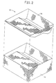
- FIG. 2 is a view of a base and lid of a porous mold having a non-regular shape.
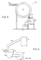
- FIG. 3 is a view of a vortex accumulator.
- FIG. 4 is a side view of filling means.
- FIG. 5a and 5b are views of stationary hoses for loading the mold.
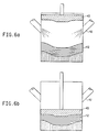
- FIG. 6a and 6b are side views of directed inlets with an associated ram for loading the mold.
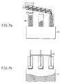
- FIG. 7a and 7b are views of a loss-in-weight device and an associated ram for loading the mold.
- FIG. 8 is a side view of the lid installation station.
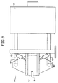
- FIG. 9 is a side view of the heating station.
- FIG. 10 is a side view of the cooling station.
- Fiber clusters are polyester fibers that are randomly arranged and entangled to form a three-dimensional nominally spherical shape, preferably with a minimum of hair extending from the surface, so as to be air-transportable. Such a shape contributes to load support and compression resistance in a molded part.
- a process according to the present invention is provided which uses rotary table 10 to convey a mold filled with polyester fiber clusters along a series of operating stations to provide a continuous process as illustrated in Fig. 1.
- Arm 9 of Fig. 4 attached to table 10 of Fig. 1, carries the lower portion of mold 12 of Fig. 2, as it is conveyed to each subsequent station.
- a rotary table has an advantage of minimizing the space required for the process.
- the process could be accomplished in a linear fashion with the operating stations located in series.
- Yet another alternative is to hold a mold stationary and bring the operating stations to the mold.
- Mold 12 is fabricated from perforated metal as shown in Fig. 2. Any material which can withstand the molding pressures inherent in the molding process, typically 6.89 - 13.79 kPa (1-2 pounds per square inch), can be used.
- molds can be fabricated from aluminum, carbon steel or stainless steel. Air flow through the mold is permitted by the open area of the perforated metal sheet. Frequently, the fiber cluster material being molded is more restrictive to air flow than is the perforated metal sheet. If the molded part has areas that have a higher concentration of fiber clusters and are thereby thicker or more dense, the air will not flow through as easily and those areas will not be readily and quickly bonded.
- the air flow is further controlled by the use of baffles or deflectors which are located adjacent the mold, the heating chamber, or both. Mold deflectors are positioned on the exterior of the top of the mold, the bottom, or both. When the deflectors are placed over those areas which would normally bond well, the heated air is redirected to those areas that are difficult to bond. Since the use of deflectors serves to restrict air flow, it is surprising that the total bonding is completed in less time versus not using deflectors.
- molds can also be used, e.g., DUOCEL® aluminum foam or reticulated vitreous carbon, both available from Energy Research and Generation, Inc., Oakland, CA. Molds can also be fabricated using fixed or removable porous inserts. Mold 12 is fabricated in two or more parts, with base 14 and lid 16 designed as required to provide the final desired shape of the cushion molded. Separate parts of the mold can be hinged for easier closing and opening of the molds.
- Typical devices such as mechanical pin type belts and rollers to open fiber clusters have a tendency to damage the clusters.
- a centrifugal blower device can be used to open the clusters prior to placement in the mold to avoid operator fatigue and increase time savings.
- a blower feeds clusters into the mold after pulling them out of a shipping container through a fill tube.
- the clusters can be opened using vortex accumulator 22 of Fig. 3.
- the clusters are brought from supply source 21 through blower 23 which reduces their density and propels them from outlet duct 24 into inlet 25 of vortex accumulator 22.
- a vortex air flow tumbles the clusters in the accumulator.
- a volume of clusters may be held in the accumulator and discharged at any time through the discharge port of the accumulator to fill the mold.
- the air stream which carries the clusters within the vortex accumulator circulates and then is vented to the outside though a vent designed to prevent discharge of the clusters.
- the vent valve is closed and the discharge valve is opened to allow the air stream to carry the clusters out through discharge port 26 to the fill station in a uniform flow.
- Vortex accumulator 22 can be positioned in either a vertical or horizontal orientation. A horizontal position is preferred since clusters can tend to become trapped by gravity in the lowest point of a vertically-oriented accumulator.
- a fiber cushion with an outer wrapping of fabric i.e. a scrim.
- This provides durability in handling the cushion prior to assembly within the final cover.
- the scrim provides integrity to minimize peeling or individual cluster flaking.
- a lightweight polyester spun bonded sheet such as DuPont SONTARA®, can be used, with a fine layer of polyester adhesive applied to the side contacting the clusters to adhere the scrim sheet to the clusters.
- the material can be precut and/or pre-sewn before its placement into the mold. Clusters are then placed on top of this scrim sheet.
- a second scrim sheet can optionally be placed over the clusters prior to the molding operation to provide complete encapsulation of the clusters.
- a spray polyester adhesive can be used instead of the scrim sheeting.
- Such an adhesive would be sprayed onto the molded article after removal from mold 12. The adhesive would harden and toughen the outside layer of clusters of the cushion. Sprayed fibers within an adhesive spray may also be used as an encapsulation agent in lieu of a scrim sheet or a scrim bag.
- variable firmness within the seat cushion.
- the sides, or bolsters of the seat have to be durable enough to withstand the abuse of entry and exit. Extra side firmness is also desirable during cornering when lateral acceleration during driving causes the occupant to be pushed against the outside of the cushion.
- a lower density is desired in the middle of the cushion to provide comfortable support for the occupant.
- the amount of clusters deposited within each section of the mold is varied.
- clusters are introduced into mold 12 of Fig. 2. Placement of the fiber clusters within mold 12 can be accomplished by several means. As noted above, clusters can be manually unloaded from a storage container and placed within the mold. Preferably, clusters are introduced into the mold automatically.
- a programmable positioning device such as a programmable robot 32 of Fig. 1, or powered x-y-z positioning device, not shown, is used to manipulate a mold fill hose through which clusters are conveyed in an air stream. The air hose is manipulated so that it is positioned over various zones of the mold for specific periods of time.
- Time in position would be dependent upon the amount of firmness desired in that particular zone of the cushion.
- Using a programmable robot or powered positioning device would enable use of several cushion profiles having unique density requirements. In addition, this would enable great savings in labor as well as creating consistency for a particular seat profile.
- Conveying loose clusters to mold 12 via an airstream creates a turbulent air flow at the discharge outlet of fill hose 38 of Fig. 4, which disturbs the desired placement of clusters.
- a vacuum is pulled on the underside of mold 12 by blower 34 of Fig. 4 through vacuum duct 35.
- the mold can be filled using stationary hoses positioned over the mold to feed specific zones of Fig. 5a and Fig. 5b.
- Fiber clusters are fed into each hose and are released into mold 12 by manipulation of gate 36 on each hose.
- Air tubes 37 allow a stream of air to be used to drive the clusters out of the hose or into the next gated section.
- Each hose will have its individual weighing and conveying apparatus attached or could be used in series in conjunction with one overall feeder system.
- Yet another alternative for variable filling of the mold is to utilize vertical pins which protrude through the bottom surface of the perforated mold to different heights in the mold cavity. This dense pack of pin heights will program a surface which allows clusters to fall in and around that surface. The greater the amount of pins within an area, the lesser the volume of clusters required to fill that zone. After the clusters have been placed in the mold, the pin device is retracted from the perforated mold and the clusters are allowed to settle prior to the molding process.
- An alternative method of gating within the mold is to utilize retractable gating rods which protrude through the side surfaces of the perforated mold. These gating rods define fill zones within the mold. Gating rods have the advantage of preventing the fiber clusters from traveling between fill zones but allowing the fiber clusters in the various fill zones to communicate and mingle, thereby eliminating shear lines between the various sections of the molded article. By varying the amount of clusters charged to various fill zones, a variable density article can be produced. For example, a seat cushion can be produced having a relatively low density seating area and a relatively high density bolster area, thereby providing a soft seat having firm lateral support. The use of fill zones eliminates the need for additional steps to achieve fill uniformity, and fill zones can be combined with any of the previously or subsequently described methods of placing the fiber clusters into the mold.
- Another alternative is to use a closed mold filling process having multiple cluster flow inlets which direct the clusters to a zone within the mold, as shown in Fig. 6a and Fig. 6b.
- Clusters are conveyed to inlets of the flow inlet 42 by an air stream or other method.
- an air stream different flow rates of clusters can be used to give different fill densities within the mold.
- Ram 43 is lowered onto the clusters after loading to compress the clusters within mold 12 to a final geometry prior to heating.
- Using a closed mold filling process eliminates the disturbance effects of turbulent air flow associated with using an air stream to convey the clusters to the mold.
- a loss-in-weight material feeder Fig. 7a and Fig. 7b
- Fig. 7a and Fig. 7b would dispense clusters to individual fill tubes 44 connected to mold 12 in amounts required by the final desired firmness of that particular zone.
- ram 45 pushes the clusters out of fill tube 44 and packs the clusters into mold 12.
- Such a device eliminates the turbulent air flow associated with using an air stream to convey the clusters to the mold.
- Another alternative is to use pre-sewn individual bags of pre-weighed clusters which are placed within the mold. Since each bag can be filled with varying amounts of clusters, different densities can be used to achieve desired firmness in various locations within the cushion. An adhesive layer must be present on the external surface of the bag as well as the internal side to ensure that the bags will adhere to each other and create a unified cushion out of the individual bags.
- wires can be places within the mold to serve as anchor points for upholstery or as reinforcement for such areas as the bolsters.
- the wires are commonly ferromagnetic to facilitate positioning in the mold by magnets, but non-ferromagnetic wire could be used where other positioning means are available.
- the wire can be coated with a polymer which has a melting point below the bonding temperature for the fiber clusters and which is sufficiently viscous at the bonding temperature so as to remain as a coating on the wire.
- the polymer melts and the clusters become imbedded in the melt. Olefins are especially advantages for coating the wire.
- the attachment between the coated wire and the bonded clusters is greater than the typical wire to polyurethane foam bond in current automotive seating.
- the olefin wire can be embedded in a polymer netting to form an anchor wire netting assembly.
- the polymer netting is preferably polyethylene.
- the anchor wire netting assembly can be placed in the mold prior to cluster bonding and thereby provides additional anchoring support.
- mold 12 After mold 12 has been charged with the clusters, mold 12 is rotated to lid installation station 40, as shown in Figs. 1 and 8.
- a second scrim sheet is placed over the cluster assembly prior to the closing of mold 12.
- Hydraulic cylinder 51 of Fig. 8 with large supporting plate 52 activates under mold 12 to support mold base 14 of Fig. 2, and reduce pressure on the rotating table assembly.
- Mold lid 16 is placed on top of mold base 14.
- Hydraulic cylinder 53 with large distribution plate 55 activates above mold 12 and applies sufficient pressure to close and latch mold 12.
- Top and bottom hydraulic cylinders 51 and 53 retract their respective supporting plates 52 and 55 and mold 12 is rotated into heating station 50 as illustrated in Fig. 1.
- hydraulic cylinders 61 and 62 are activated to position air ducts 63 and 64 into contact with mold 12 to provide a route of air circulation between the mold and the heat source.
- Forced hot air between 150-245 degrees C, is supplied to mold 12.
- the heated air activates the binder fibers within the fiber clusters which provides the adhesive to provide form to the molded part.
- the air is heated by use of commercial oven 66 which has been modified to include hydraulically operated ducts for directing the air flow.
- hot air enters the mold cavity from the bottom and exits at the top of the mold.
- heated air can be fed through the top surface of the mold, or can be directed alternately through the top and bottom mold surfaces.
- the heating cycle depends on many factors, including the density of the fiber clusters mass, the air temperature, and the resistance of the perforated mold surface to air flow. For economic reasons it is preferable to work with a high air flow and thus minimize the duration of the heating cycle.
- fiber clusters are thermoplastic and will become less capable of resisting the crushing forces of the bonding air as the bonding temperature is reached. In order to reduce molding time, it is desirable to reduce the air flow rate during a bonding cycle so as to keep the crushing force of the forced air below the crush resistance of the heated clusters.
- Air pressure on the molded surface is controlled by an electrically controlled variable speed blower. The pressure drop across the molded part is monitored using a pressure reading or recording device, such as a manometer, not shown.
- hydraulic cylinders 61 and 62 are activated to release their contact with mold 12.
- Mold 12 is rotated to cooling station 70, as shown in Figs. 1 and 10.
- Hydraulic cylinders 71 and 72 are activated to position air ducts 73 and 74 into contact with mold 12 to provide a route of air circulation between the mold and the source of cooling air.
- Cool air is forced through mold 12 using electrically controlled variable speed blower 75 as indicated in Fig. 10. Again, the air flow can be through the bottom of mold 12, through the top of mold 12, or a combination of both directions.
- a substantial part of the energy can be recovered in the cooling zone and used to heat the air intake of the heating system by channeling the cooling air from mold 12 to oven 66 using air duct 62.
- this air stream can be directed to preheat station 80 of Fig. 1, where the preheated air is forced into mold 12 prior to the full heating cycle. This "preheating" will lower molding time at the heating station.
- hydraulic cylinders 71 and 72 are activated to release their contact with mold 12 and the mold is rotated away from cooling station 70.
- the molded part is removed from mold 12. Removal can be accomplished manually or through automated means.
- the bottom of mold 12 should preferably have a movable base, which can be pushed upwards to free the molded piece.
- the molded part may be encapsulated within a heat shrinkable polyester "bag” after molding.
- the encapsulating bag upon heating, will conform to the shape of the molded part and provide durability and improved appearance to the part.
- an end use covering can be molded directly onto the article.
- an automotive seat cushion having the desired final fabric, upholstery, or leather covering can be integrally molded with a seat cushion made from fiber clusters.
- porous fabrics have been bonded to foam material by methods employing superheated steam to melt a polymer adhesive layer, thereby bonding the seat covering to the foam seat.
- a steam process is limited in that it cannot be used to mold non-porous fabrics such as leather, and also has the disadvantages of utilizing expensive superheated steam and requiring condensate removal.
- the desired final seat covering for example leather
- a thermoplastic adhesive film such as the one manufactured by Bemis Associates, Shirley, MA is cut to conform to the shape of the mold.
- the leather covering is then placed in the mold, and the thermoplastic adhesive film is subsequently placed in the mold atop the leather covering.
- the mold is charged with fiber clusters, closed, and heated as discussed previously. Heating time can be determined by monitoring the air flow through the mold. A pressure drop indicates that the thermoplastic adhesive film has melted.
- a seat cushion having a final covering is obtained. The value of this integral seat cushion and covering process is obvious in light of the elimination of the subsequent and costly additional steps required to cover seat cushions.
Landscapes
- Engineering & Computer Science (AREA)
- Mechanical Engineering (AREA)
- Chemical & Material Sciences (AREA)
- Composite Materials (AREA)
- Textile Engineering (AREA)
- Nonwoven Fabrics (AREA)
- Casting Or Compression Moulding Of Plastics Or The Like (AREA)
- Moulds For Moulding Plastics Or The Like (AREA)
- Processing And Handling Of Plastics And Other Materials For Molding In General (AREA)
- Separation, Recovery Or Treatment Of Waste Materials Containing Plastics (AREA)
- Mattresses And Other Support Structures For Chairs And Beds (AREA)
- Treatment Of Fiber Materials (AREA)
Abstract
Claims (23)
- Procédé automatisé de moulage de coussins recyclables à partir d'amas de fibres détachés, composés de fibres de polyester et de fibres de liaison thermoliables, le procédé connu comprenant les étapes de chargement d'une nappe continue d'amas de fibres dans un moule, de placement du moule dans un four, de placement du moule dans une chambre de refroidissement et d'enlèvement du coussin moulé du moule, l'amélioration comprenant les étapes suivantes:a) chargement d'amas de fibres détachés dans le moule;b) guidage d'air chauffé d'un four vers le moule, de sorte à faire fondre les fibres de liaison thermoliables, sans placer le moule dans le four, récupération de l'air d'échappement du moule et recyclage de l'air d'échappement vers le four; etc) guidage d'air froid vers le moule pour refroidir le coussin, récupération de l'air d'échappement du moule et recyclage de l'air d'échappement vers un refroidisseur d'air, le four ou une station de préchauffage.
- Procédé automatisé selon la revendication 1, comprenant en outre l'étape d'établissement d'un vide sur le côté inférieur du moule, de sorte que les amas de fibres détachés sont reçus et confinés dans le moule.
- Procédé automatisé selon la revendication 1, comprenant en outre l'étape d'agencement d'un matériau de couverture du siège dans le moule avant le chargement des amas de fibres détachés, et d'agencement d'un adhésif thermoplastique au-dessus du matériau de couverture du siège.
- Procédé automatisé selon la revendication 3, dans lequel le matériau de couverture du siège est non poreux.
- Procédé automatisé selon la revendication 4, dans lequel le matériau de couverture du siège est du cuir.
- Procédé automatisé selon la revendication 1, comprenant en outre l'étape d'encapsulage des amas de fibres détachés dans le moule.
- Procédé automatisé selon la revendication 6, dans lequel l'étape d'encapsulage comprend en outre la garniture d'une partie du moule d'une feuille de gaze.
- Procédé automatisé selon la revendication 6, dans lequel l'étape d'encapsulage comprend en outre la garniture d'une partie du moule d'un adhésif d'encapsulage.
- Procédé automatisé selon la revendication 6, dans lequel l'étape d'encapsulage comprend en outre la vaporisation de fibres d'encapsulage dans le moule.
- Procédé automatisé selon la revendication 6, dans lequel l'étape d'encapsulage comprend en outre l'agencement des amas de fibres dans des sacs en gaze individuels.
- Procédé automatisé selon la revendication 1, dans lequel le moule comporte plusieurs zones de remplissage.
- Procédé automatisé selon la revendication 11, dans lequel l'étape de chargement comprend en outre la variation de la quantité d'amas de fibres détachés introduite dans les différentes zones de remplissage du moule, de sorte à produire un article à densité variable.
- Procédé automatisé selon la revendication 12, dans lequel l'étape de chargement comprend en outre l'introduction automatique d'amas de fibres détachés dans le moule par l'intermédiaire d'un dispositif de positionnement programmable.
- Procédé automatisé selon la revendication 12, dans lequel l'étape de chargement comprend en outre l'utilisation de tuyaux stationnaires positionnés au-dessus du moule pour alimenter des zones de remplissage spécifiques.
- Procédé automatisé selon la revendication 12, dans lequel l'étape de chargement comprend en outre l'utilisation d'ergots verticaux débordant à travers une surface inférieure du moule, à des hauteurs différentes dans la cavité du moule, pour définir et séparer ainsi davantage les zones de remplissage.
- Procédé automatisé selon la revendication 12, dans lequel l'étape de chargement comprend en outre l'utilisation de plusieurs tiges d'obturation débordant à travers une surface latérale du moule, pour définir et séparer ainsi davantage les zones de remplissage.
- Procédé automatisé selon la revendication 12, dans lequel l'étape de chargement comprend en outre la fermeture du moule et le remplissage ultérieur du moule par l'intermédiaire de plusieurs entrées d'écoulement d'amas de fibres dirigés vers les différentes zones de remplissage dans le moule.
- Procédé automatisé selon la revendication 12, dans lequel l'étape de chargement comprend en outre l'agencement de plusieurs sacs individuels d'amas de fibres prépesés dans le moule.
- Procédé automatisé selon la revendication 1, comprenant en outre l'étape d'encapsulage du coussin moulé.
- Procédé automatisé selon la revendication 1, comprenant en outre l'étape d'agencement d'un fil d'ancrage dans le moule avant le chauffage.
- Procédé automatisé selon la revendication 20, comprenant en outre l'étape de revêtement du fil d'ancrage d'un polymère ayant un point de fusion inférieur à la température de liaison des amas de fibres.
- Procédé automatisé selon la revendication 21, comprenant en outre l'étape d'enrobage du fil revêtu dans un réseau polymère.
- Procédé automatisé selon la revendication 1, comprenant en outre les étapes ci-dessous:(a) positionnement d'une base d'un moule sur une plaque de retenue connectée à un bras d'un assemblage de table rotative;(b) ouverture des amas de fibres tassés, d'un état dense vers un état détaché à densité réduite;(c) agencement d'une feuille d'encapsulage sur la base du moule avant le chargement des amas de fibres, ladite feuille d'encapsulage comportant un adhésif sur sa surface interne;(d) chargement des amas de fibres détachés, composés de fibres de polyester et de fibres de liaison thermoliables sur la feuille d'encapsulage dans la base du moule pour former un assemblage d'amas de fibres;(e) transfert par rotation de la base du moule vers une station d'installation du couvercle dans laquelle un couvercle du moule est agencé sur le moule pour former un moule fermé;(f) transfert par rotation du moule fermé vers une station de chauffage, dans laquelle de l'air chaud est guidé à partir d'un four et entraíné à travers l'assemblage d'amas de fibres dans ledit moule, de sorte à faire fondre les fibres de liaison thermoliables;(g) transfert par rotation du moule fermé vers une station de refroidissement, dans laquelle de l'air froid est entraíné à travers ledit assemblage d'amas de fibres dans le moule; et(h) enlèvement du coussin moulé du moule.
Applications Claiming Priority (5)
| Application Number | Priority Date | Filing Date | Title |
|---|---|---|---|
| US08/274,501 US5454992A (en) | 1994-07-13 | 1994-07-13 | Fiber clusters molding process and equipment |
| US274501 | 1994-07-13 | ||
| US49587595A | 1995-06-28 | 1995-06-28 | |
| US495875 | 1995-06-28 | ||
| PCT/US1995/008439 WO1996002693A1 (fr) | 1994-07-13 | 1995-07-10 | Procede et equipement de moulage utilisant des amas de fibres |
Publications (2)
| Publication Number | Publication Date |
|---|---|
| EP0770154A1 EP0770154A1 (fr) | 1997-05-02 |
| EP0770154B1 true EP0770154B1 (fr) | 1998-09-23 |
Family
ID=26956866
Family Applications (1)
| Application Number | Title | Priority Date | Filing Date |
|---|---|---|---|
| EP95926624A Expired - Lifetime EP0770154B1 (fr) | 1994-07-13 | 1995-07-10 | Procede de moulage utilisant des amas de fibres |
Country Status (8)
| Country | Link |
|---|---|
| US (1) | US5942175A (fr) |
| EP (1) | EP0770154B1 (fr) |
| JP (1) | JP3571724B2 (fr) |
| CA (1) | CA2192945C (fr) |
| DE (1) | DE69504987T2 (fr) |
| ES (1) | ES2122662T3 (fr) |
| MX (1) | MX9700357A (fr) |
| WO (1) | WO1996002693A1 (fr) |
Families Citing this family (11)
| Publication number | Priority date | Publication date | Assignee | Title |
|---|---|---|---|---|
| SE515814C2 (sv) * | 2000-10-11 | 2001-10-15 | Nila I Naessjoe Ab | Sätt och medel vid framställning av formade kuddar med fodral |
| DE10324735B3 (de) * | 2003-05-30 | 2004-11-11 | Fiber Engineering Gmbh | Verfahren und Vorrichtung zur Herstellung von dreidimensional ausgeprägten Formteilen sowie Formteil |
| US7144813B2 (en) * | 2004-11-12 | 2006-12-05 | Semitool, Inc. | Method and apparatus for thermally processing microelectronic workpieces |
| US20080203083A1 (en) * | 2007-02-28 | 2008-08-28 | Wirth Paul Z | Single wafer anneal processor |
| FR2921941A1 (fr) | 2007-10-03 | 2009-04-10 | Charles Weiskopf | Dispositif de fabrication d'une nappe de fibres non tissees |
| DE102007054424A1 (de) * | 2007-11-13 | 2009-05-28 | Robert Bürkle GmbH | Vorrichtung zum Herstellen von Formteilen aus Fasermaterial |
| DE102008035611A1 (de) | 2008-07-31 | 2010-02-04 | Johnson Controls Gmbh | Polsterelement, insbesondere ein Sitzpolsterelement unterschiedlicher Härtezonen zur Verwendung in einem Kraftfahrzeug, Verfahren zur Herstellung eines Polsterelements und Fahrzeugsitz |
| US9144943B2 (en) | 2012-02-15 | 2015-09-29 | Olbrich Gmbh | Fiber mold filling system and method |
| EP2695980A1 (fr) | 2012-08-06 | 2014-02-12 | Oskar Dilo Maschinenfabrik KG | Dispositif d'acheminement pour fibres ou flocons |
| CA2967507C (fr) * | 2015-01-16 | 2019-03-19 | Schukra Geratebau Gmbh | Procede, outil et systeme de production d'un produit a partir d'un materiau fibreux |
| JP7124032B2 (ja) * | 2020-10-28 | 2022-08-23 | 本田技研工業株式会社 | 成型品の製造方法 |
Family Cites Families (23)
| Publication number | Priority date | Publication date | Assignee | Title |
|---|---|---|---|---|
| US3032774A (en) * | 1955-11-30 | 1962-05-08 | American Viscose Corp | Seamless garment |
| US4794038A (en) * | 1985-05-15 | 1988-12-27 | E. I. Du Pont De Nemours And Company | Polyester fiberfill |
| US5238612A (en) * | 1985-05-15 | 1993-08-24 | E. I. Du Pont De Nemours And Company | Fillings and other aspects of fibers |
| EP0217883B1 (fr) * | 1985-04-09 | 1990-09-19 | Messerschmitt-Bölkow-Blohm Gesellschaft mit beschränkter Haftung | Ame de rembourrage, en particulier pour un siege d'avion, et son procede de fabrication |
| US5194311A (en) * | 1985-04-09 | 1993-03-16 | Deutsche Airbus Gmbh | Cushioning core and seat construction especially for an aircraft seat |
| US4940502A (en) * | 1985-05-15 | 1990-07-10 | E. I. Du Pont De Nemours And Company | Relating to bonded non-woven polyester fiber structures |
| US5169580A (en) * | 1985-05-15 | 1992-12-08 | E. I. Du Pont De Nemours And Company | Bonded non-woven polyester fiber structures |
| US5500295A (en) * | 1985-05-15 | 1996-03-19 | E. I. Du Pont De Nemours And Company | Fillings and other aspects of fibers |
| US5294392A (en) * | 1985-05-15 | 1994-03-15 | E. I. Du Pont De Nemours And Company | Method of making bonded non-woven polyester fiber structures using fiberballs |
| DE3700680A1 (de) * | 1987-01-12 | 1988-07-21 | Breveteam Sa | Faserkugeln enthaltendes fuellgut, insbesondere fuer decken oder als polstermaterial |
| CA1303837C (fr) * | 1987-01-12 | 1992-06-23 | Gunter Tesch | Granulat a base de fibres et procede de fabrication connexe |
| JPS63218316A (ja) * | 1987-03-06 | 1988-09-12 | Inoue Mtp Co Ltd | 異硬度座席クツシヨンの製造方法 |
| JP2513500B2 (ja) * | 1988-10-03 | 1996-07-03 | 株式会社ブリヂストン | 自動車用内装材 |
| JP2909112B2 (ja) * | 1989-11-30 | 1999-06-23 | 日本発条株式会社 | クッション材の製造方法 |
| FI86537C (fi) * | 1990-06-08 | 1992-09-10 | Juha Vesa | Anordning foer framstaellning av formkroppar. |
| EP0538372B1 (fr) * | 1990-07-09 | 1995-07-26 | E.I. Du Pont De Nemours And Company | Ameliorations relatives a des structures de fibres de polyester non tissees collees |
| JPH05177066A (ja) * | 1991-07-30 | 1993-07-20 | Toyo Kutsushiyon Kk | パット材の製造方法 |
| JP2944833B2 (ja) * | 1991-10-07 | 1999-09-06 | ヒクマ株式会社 | クッション材、防音材およびその製造方法 |
| JPH05220278A (ja) * | 1992-02-12 | 1993-08-31 | Nhk Spring Co Ltd | クッション体およびその製造方法 |
| JP2882179B2 (ja) * | 1992-04-24 | 1999-04-12 | トヨタ自動車株式会社 | クッション材の製造方法 |
| JPH0623771A (ja) * | 1992-07-03 | 1994-02-01 | Araco Corp | 木質系成形基材の製造方法 |
| JPH0649760A (ja) * | 1992-07-28 | 1994-02-22 | Iwamoto Seisakusho:Kk | ラップの熱接着による立体的形状の成形方法及びその装置 |
| JP3365838B2 (ja) * | 1993-10-29 | 2003-01-14 | しげる工業株式会社 | 車両用シートの製造方法 |
-
1995
- 1995-07-10 DE DE69504987T patent/DE69504987T2/de not_active Expired - Fee Related
- 1995-07-10 ES ES95926624T patent/ES2122662T3/es not_active Expired - Lifetime
- 1995-07-10 CA CA002192945A patent/CA2192945C/fr not_active Expired - Fee Related
- 1995-07-10 MX MX9700357A patent/MX9700357A/es not_active IP Right Cessation
- 1995-07-10 EP EP95926624A patent/EP0770154B1/fr not_active Expired - Lifetime
- 1995-07-10 WO PCT/US1995/008439 patent/WO1996002693A1/fr not_active Ceased
- 1995-07-10 JP JP50506596A patent/JP3571724B2/ja not_active Expired - Fee Related
-
1996
- 1996-09-06 US US08/706,629 patent/US5942175A/en not_active Expired - Fee Related
Also Published As
| Publication number | Publication date |
|---|---|
| US5942175A (en) | 1999-08-24 |
| EP0770154A1 (fr) | 1997-05-02 |
| ES2122662T3 (es) | 1998-12-16 |
| CA2192945C (fr) | 2005-05-24 |
| DE69504987T2 (de) | 1999-03-25 |
| WO1996002693A1 (fr) | 1996-02-01 |
| JP3571724B2 (ja) | 2004-09-29 |
| JPH10504067A (ja) | 1998-04-14 |
| CA2192945A1 (fr) | 1996-02-01 |
| DE69504987D1 (de) | 1998-10-29 |
| MX9700357A (es) | 1997-04-30 |
Similar Documents
| Publication | Publication Date | Title |
|---|---|---|
| US5885693A (en) | Shaped plastic foam part having portions of different density | |
| EP0770154B1 (fr) | Procede de moulage utilisant des amas de fibres | |
| CN100586344C (zh) | 由弹性结构树脂成型品构成的缓冲材料及其制造方法以及在所述制造方法中使用的模具 | |
| TW387954B (en) | Forming of fiber assembly | |
| JP3348172B2 (ja) | 繊維弾性体の成形方法 | |
| EP0591553B1 (fr) | Produit de moulage avec croute a base de resine de polypropylene et a expansion dans le moule, et procede de production correspondant | |
| EP0672771A2 (fr) | Procédé et dispositif pour la fabrication de coussins en fibres | |
| JPH08118520A (ja) | 永久変形に対する抵抗を改良した車両シート部品の製造方法 | |
| US6221292B1 (en) | Apparatus and method for molding polymeric fibers into products | |
| US6379595B1 (en) | Multiple density interior trim substrate and method of making same | |
| EP2628588B1 (fr) | Système de remplissage de moule par des fibres et méthode | |
| US6576172B1 (en) | Method of manufacturing sound-proof products | |
| JPH01198314A (ja) | 複合成形体の製造方法及びその製造装置 | |
| US5454992A (en) | Fiber clusters molding process and equipment | |
| JP2003251089A (ja) | スプリング構造樹脂成形品から成るクッション材の製造方法 | |
| JP2001060090A (ja) | 防音材の製造方法 | |
| US7682141B2 (en) | Production apparatus for forming plastic molded articles | |
| US3211600A (en) | Method of making composite contoured carpeting | |
| JP3827995B2 (ja) | 繊維成形体の製造方法及び製造装置 | |
| DK181939B1 (en) | PILLOW AND METHOD FOR MANUFACTURING A PILLOW | |
| CN119138730A (zh) | 衬垫及制造系统和方法 | |
| CN119217760A (zh) | 一种形成网状结构的系统和方法 | |
| JP3643269B2 (ja) | 防音材の製造方法 | |
| JPH10280265A (ja) | 繊維集合体によるクッション成形品 | |
| JPH09109164A (ja) | カーペット廃材熱プレス成形品及びその製造方法 |
Legal Events
| Date | Code | Title | Description |
|---|---|---|---|
| PUAI | Public reference made under article 153(3) epc to a published international application that has entered the european phase |
Free format text: ORIGINAL CODE: 0009012 |
|
| 17P | Request for examination filed |
Effective date: 19961219 |
|
| AK | Designated contracting states |
Kind code of ref document: A1 Designated state(s): DE ES FR GB IT |
|
| GRAG | Despatch of communication of intention to grant |
Free format text: ORIGINAL CODE: EPIDOS AGRA |
|
| 17Q | First examination report despatched |
Effective date: 19971119 |
|
| GRAG | Despatch of communication of intention to grant |
Free format text: ORIGINAL CODE: EPIDOS AGRA |
|
| GRAH | Despatch of communication of intention to grant a patent |
Free format text: ORIGINAL CODE: EPIDOS IGRA |
|
| GRAH | Despatch of communication of intention to grant a patent |
Free format text: ORIGINAL CODE: EPIDOS IGRA |
|
| GRAA | (expected) grant |
Free format text: ORIGINAL CODE: 0009210 |
|
| AK | Designated contracting states |
Kind code of ref document: B1 Designated state(s): DE ES FR GB IT |
|
| REF | Corresponds to: |
Ref document number: 69504987 Country of ref document: DE Date of ref document: 19981029 |
|
| ET | Fr: translation filed | ||
| REG | Reference to a national code |
Ref country code: ES Ref legal event code: FG2A Ref document number: 2122662 Country of ref document: ES Kind code of ref document: T3 |
|
| PLBE | No opposition filed within time limit |
Free format text: ORIGINAL CODE: 0009261 |
|
| STAA | Information on the status of an ep patent application or granted ep patent |
Free format text: STATUS: NO OPPOSITION FILED WITHIN TIME LIMIT |
|
| 26N | No opposition filed | ||
| REG | Reference to a national code |
Ref country code: GB Ref legal event code: IF02 |
|
| REG | Reference to a national code |
Ref country code: GB Ref legal event code: 732E |
|
| REG | Reference to a national code |
Ref country code: GB Ref legal event code: 732E |
|
| PGFP | Annual fee paid to national office [announced via postgrant information from national office to epo] |
Ref country code: GB Payment date: 20050706 Year of fee payment: 11 |
|
| PGFP | Annual fee paid to national office [announced via postgrant information from national office to epo] |
Ref country code: DE Payment date: 20050707 Year of fee payment: 11 |
|
| PGFP | Annual fee paid to national office [announced via postgrant information from national office to epo] |
Ref country code: FR Payment date: 20050708 Year of fee payment: 11 |
|
| PGFP | Annual fee paid to national office [announced via postgrant information from national office to epo] |
Ref country code: ES Payment date: 20050818 Year of fee payment: 11 |
|
| PG25 | Lapsed in a contracting state [announced via postgrant information from national office to epo] |
Ref country code: GB Free format text: LAPSE BECAUSE OF NON-PAYMENT OF DUE FEES Effective date: 20060710 |
|
| PGFP | Annual fee paid to national office [announced via postgrant information from national office to epo] |
Ref country code: IT Payment date: 20060731 Year of fee payment: 12 |
|
| PG25 | Lapsed in a contracting state [announced via postgrant information from national office to epo] |
Ref country code: DE Free format text: LAPSE BECAUSE OF NON-PAYMENT OF DUE FEES Effective date: 20070201 |
|
| GBPC | Gb: european patent ceased through non-payment of renewal fee |
Effective date: 20060710 |
|
| REG | Reference to a national code |
Ref country code: FR Ref legal event code: ST Effective date: 20070330 |
|
| REG | Reference to a national code |
Ref country code: ES Ref legal event code: FD2A Effective date: 20060711 |
|
| PG25 | Lapsed in a contracting state [announced via postgrant information from national office to epo] |
Ref country code: ES Free format text: LAPSE BECAUSE OF NON-PAYMENT OF DUE FEES Effective date: 20060711 |
|
| PG25 | Lapsed in a contracting state [announced via postgrant information from national office to epo] |
Ref country code: FR Free format text: LAPSE BECAUSE OF NON-PAYMENT OF DUE FEES Effective date: 20060731 |
|
| PG25 | Lapsed in a contracting state [announced via postgrant information from national office to epo] |
Ref country code: IT Free format text: LAPSE BECAUSE OF NON-PAYMENT OF DUE FEES Effective date: 20070710 |