EP0770418A1 - Procédé pour la purification d'une natte filtrante non-tissée - Google Patents
Procédé pour la purification d'une natte filtrante non-tissée Download PDFInfo
- Publication number
- EP0770418A1 EP0770418A1 EP96116415A EP96116415A EP0770418A1 EP 0770418 A1 EP0770418 A1 EP 0770418A1 EP 96116415 A EP96116415 A EP 96116415A EP 96116415 A EP96116415 A EP 96116415A EP 0770418 A1 EP0770418 A1 EP 0770418A1
- Authority
- EP
- European Patent Office
- Prior art keywords
- filter mat
- filter
- mat
- thickness
- rollers
- Prior art date
- Legal status (The legal status is an assumption and is not a legal conclusion. Google has not performed a legal analysis and makes no representation as to the accuracy of the status listed.)
- Ceased
Links
- 238000000034 method Methods 0.000 title claims abstract description 16
- 238000004140 cleaning Methods 0.000 title claims description 6
- 239000002245 particle Substances 0.000 claims abstract description 24
- 239000003973 paint Substances 0.000 claims abstract description 18
- 230000005484 gravity Effects 0.000 claims description 5
- 239000002904 solvent Substances 0.000 claims description 4
- 238000001914 filtration Methods 0.000 claims description 2
- 239000007921 spray Substances 0.000 abstract description 2
- 101100495270 Caenorhabditis elegans cdc-26 gene Proteins 0.000 description 35
- 239000000428 dust Substances 0.000 description 7
- 238000010422 painting Methods 0.000 description 7
- 101150054854 POU1F1 gene Proteins 0.000 description 3
- 239000000443 aerosol Substances 0.000 description 3
- 238000012423 maintenance Methods 0.000 description 3
- 238000000926 separation method Methods 0.000 description 3
- 239000002699 waste material Substances 0.000 description 3
- XLYOFNOQVPJJNP-UHFFFAOYSA-N water Substances O XLYOFNOQVPJJNP-UHFFFAOYSA-N 0.000 description 3
- 230000009471 action Effects 0.000 description 2
- 230000008859 change Effects 0.000 description 1
- 239000013043 chemical agent Substances 0.000 description 1
- 230000000694 effects Effects 0.000 description 1
- 239000007788 liquid Substances 0.000 description 1
- 230000000737 periodic effect Effects 0.000 description 1
- 230000009467 reduction Effects 0.000 description 1
- 230000008929 regeneration Effects 0.000 description 1
- 238000011069 regeneration method Methods 0.000 description 1
- 230000003716 rejuvenation Effects 0.000 description 1
- 230000000717 retained effect Effects 0.000 description 1
- 239000007787 solid Substances 0.000 description 1
Images

Classifications
-
- B—PERFORMING OPERATIONS; TRANSPORTING
- B01—PHYSICAL OR CHEMICAL PROCESSES OR APPARATUS IN GENERAL
- B01D—SEPARATION
- B01D46/00—Filters or filtering processes specially modified for separating dispersed particles from gases or vapours
- B01D46/18—Particle separators, e.g. dust precipitators, using filtering belts
- B01D46/22—Particle separators, e.g. dust precipitators, using filtering belts the belts travelling during filtering
-
- B—PERFORMING OPERATIONS; TRANSPORTING
- B01—PHYSICAL OR CHEMICAL PROCESSES OR APPARATUS IN GENERAL
- B01D—SEPARATION
- B01D46/00—Filters or filtering processes specially modified for separating dispersed particles from gases or vapours
- B01D46/66—Regeneration of the filtering material or filter elements inside the filter
- B01D46/74—Regeneration of the filtering material or filter elements inside the filter by forces created by movement of the filter element
-
- B—PERFORMING OPERATIONS; TRANSPORTING
- B05—SPRAYING OR ATOMISING IN GENERAL; APPLYING FLUENT MATERIALS TO SURFACES, IN GENERAL
- B05B—SPRAYING APPARATUS; ATOMISING APPARATUS; NOZZLES
- B05B14/00—Arrangements for collecting, re-using or eliminating excess spraying material
- B05B14/40—Arrangements for collecting, re-using or eliminating excess spraying material for use in spray booths
- B05B14/43—Arrangements for collecting, re-using or eliminating excess spraying material for use in spray booths by filtering the air charged with excess material
Definitions
- the invention relates to a method for cleaning a fleece-like filter mat of a filter device according to the preamble of claim 1 and to a device for performing the method.
- the air containing the paint particles is passed through a water spray curtain.
- the paint particles washed out by the water must then be separated from the water again using chemical agents and the waste that arises must be disposed of as special waste.
- the aerosol extracted from the paint room is passed through a filter mat in which the filtered paint particles accumulate.
- the paint particles are usually already in solid form, but even if the filter mat is arranged in the area immediately behind the workpiece to be painted and the paint particles still hit the filter mat in liquid form, the paint particles do not form a stronger bond with the filter mat and dry out immediately.
- the paint particles are sucked off with a vacuum cleaner. This extracted paint dust has dried out, is no longer chemically reactive and therefore does not have to be disposed of as special waste. This results in significant cost advantages over the wet separation process.
- the object of the invention is to provide a method of the type mentioned above, which is significantly simplified compared to the known methods. According to the invention, this is achieved by tapering the thickness of the filter mat in some areas and then allowing it to expand again to its thickness, the area in which the filter mat is tapered being successively changed over essentially the entire extent of the filter mat.
- the regionally tapering of the thickness of the filter mat is achieved by guiding the filter mat around a roller whose diameter is in the region of the thickness of the filter mat or is smaller than this.
- the regionally tapering of the thickness of the filter mat is achieved by guiding the filter mat between two rollers, which are arranged at a fixed distance from one another, which is smaller than the thickness of the filter mat.
- the filter device illustrated schematically in FIG. 1 is installed in a pit 1 of a painting room, not shown, which is covered with a grid 3.
- the air of the painting room enriched with paint particles or solvent particles is drawn off by an air suction device 2 through a fleece-like filter mat 4, the color particles or solvent particles being largely retained by the filter mat 4 and being deposited in or on the latter.
- This fleece-like filter mat 4 is fixed on an endless, air-permeable carrier belt 5, which is guided in the manner of a conveyor belt around two stationary rollers 6 and 7 by which at least one roller is driven.
- the drive can work continuously or periodically.
- the filter belt is moved at a speed of approx. 0.05 to 2 m / sec, the selected speed depending on the scope of the painting operation.
- This carrier tape 5 absorbs tensile forces and ensures the frictional connection to the driven roller 6. It is essential that these rollers 6 and 7 or at least one of these rollers have a diameter which is in the region of the thickness s of the filter mat 4 or is smaller than this. If the filter mat 4 is moved by the driven roller 6, for example in the direction of the arrow 12, it is stretched in the areas which run around the rollers 6 and 7 due to the small diameter d of these rollers 6 and 7 and thereby in their strength s significantly rejuvenated. As soon as these areas have passed, the filter mat 4 expands again to its original thickness s owing to the inherent elasticity. As a result of these mechanical effects during the tapering and due to the subsequent expansion, a large part of the particle dust located in the filter mat 4 is released from the affected areas and, due to the action of gravity, falls into the collecting container 8 provided below these rollers 6 and 7.
- each point of the filter mat 4 has passed one of the rollers 6, 7.
- the area in which the filter mat 4 was tapered and then allowed to expand again has thus been successively changed over the entire extent of the filter mat 4. A large part of the particle dust in the filter mat 4 was thereby removed.
- the cleaning of the filter mat 4 can be carried out continuously by the filter mat 4 constantly rotating during the painting work in the manner of an endless belt. However, one or more cleaning cycles can also be carried out during a break in the painting work.
- the entire carrier tape 5 is provided over its width and length with a filter mat 4, which therefore has approximately twice the length of the pit 1. But it would also be possible to provide only about half of the carrier tape 5 with a filter mat 4 having the simple length of the pit. After cleaning the filter mat 4, the correct position of the carrier tape in which the filter mat is directly adjacent to the grating 3 in its entire length would then have to be ensured.
- FIG. 2 Another embodiment of the invention is shown in FIG. 2.
- the filter mat 4 shown here only partially or its carrier tape 5 is guided over rollers 9, 10, 11, the diameter of which is greater than the thickness s of the filter mat 4, the one roller 10 being driven by a drive device. Due to the size of the diameter of the rollers 9, 10 and 11, the filter mat 4 is hardly tapered in its thickness when it rotates around it, so that no paint dust is separated out in these areas.
- the filter mat 4 is guided around a further roller 16, the diameter d of which is less than or equal to the thickness s of the filter mat 4. In the area of the filter mat 4 adjacent to this roller 16, the thickness of the filter mat is reduced as it runs around the roller 16 and then expands again to its original thickness, with a large part of the dust stored in the filter mat 4 coming down from the filter mat falls.
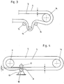
- FIG. 3 A similar embodiment of the invention is shown schematically in FIG. 3.
- the filter mat 4 runs around a roller 14 with a large diameter and around rollers 15 with a small diameter, in the area of which the particle dust is separated from the filter mat 4.
- the filter mat runs around rollers whose diameter is less than or equal to the thickness of the filter mat.
- Fig. 4 an embodiment of the invention is shown, in which the filter mat 4 is guided between two rollers 17 and 18, which are arranged on a support frame 19 at a fixed distance a from each other, which is smaller than that Thickness s of the filter mat 4.
- the filter mat 4 is moved by the rollers 17 and 18 which form a kind of doctor blade, the area 8 of the filter mat 4 between the two rollers being tapered and then expanded again.
- the diameter of the rollers 17 and 18 is therefore not decisive in comparison with the thickness of the filter mat 4, but rather their mutual distance from one another.
- the filter mat 4 could also be designed to be stationary and the support frame 19 together with the rollers 17 and 18 could be moved, the filter mat then being moved back and forth at least in sections so that all of its sections and regions pass through the rollers 17 and 18.
- the filter device according to the invention does not have to be installed in a pit 1, but could, for example, also be arranged in an upright housing which is located directly in the area behind the workpiece to be painted. Rollers do not necessarily have to be used to taper the filter mat in certain areas. For example, a stamp could be provided, which can carry out a linear forward and backward movement and in this case compresses a region of the filter mat and allows it to expand again. Regardless of the particular arrangement of the filter mat and its design, the arrangement is to be chosen and designed such that at least a portion of the surface of the respective tapered area of the filter mat is directed approximately to the side or downward, so that the filter mat 4 located in and particles to be removed can fall out of the filter mat 4 due to their own weight.
- the filter mat can be cleaned very effectively without requiring an additional external energy supply.
- the periodic change in thickness imposed on the filter mat is sufficient for this.
Landscapes
- Chemical & Material Sciences (AREA)
- Chemical Kinetics & Catalysis (AREA)
- Details Or Accessories Of Spraying Plant Or Apparatus (AREA)
- Filtering Materials (AREA)
Applications Claiming Priority (2)
| Application Number | Priority Date | Filing Date | Title |
|---|---|---|---|
| AT1755/95 | 1995-10-24 | ||
| AT0175595A AT402477B (de) | 1995-10-24 | 1995-10-24 | Verfahren zum reinigen einer vliesartigen filtermatte |
Publications (1)
| Publication Number | Publication Date |
|---|---|
| EP0770418A1 true EP0770418A1 (fr) | 1997-05-02 |
Family
ID=3520310
Family Applications (1)
| Application Number | Title | Priority Date | Filing Date |
|---|---|---|---|
| EP96116415A Ceased EP0770418A1 (fr) | 1995-10-24 | 1996-10-14 | Procédé pour la purification d'une natte filtrante non-tissée |
Country Status (2)
| Country | Link |
|---|---|
| EP (1) | EP0770418A1 (fr) |
| AT (1) | AT402477B (fr) |
Cited By (4)
| Publication number | Priority date | Publication date | Assignee | Title |
|---|---|---|---|---|
| DE202011101156U1 (de) | 2011-05-27 | 2011-08-03 | Rainer Berkmann | Filteranlage |
| DE102011102617A1 (de) | 2011-05-27 | 2012-11-29 | Berkmann NT Ingenieurbüro | Filteranlage |
| CN105999907A (zh) * | 2016-07-07 | 2016-10-12 | 北京巨维通科技有限公司 | 一种带有防滑无纺布的室外雾霾过滤器 |
| IT201600076526A1 (it) * | 2016-07-21 | 2018-01-21 | Geico Spa | Cabina di verniciatura con sistema di filtraggio dell'overspray con tappeto sostituibile |
Citations (6)
| Publication number | Priority date | Publication date | Assignee | Title |
|---|---|---|---|---|
| US2881861A (en) * | 1957-02-18 | 1959-04-14 | American Air Filter Co | Air flow seal for air filter having an expansible-contractible air cleaning web |
| US3328941A (en) * | 1966-06-30 | 1967-07-04 | Space Conditioning Inc | Air treating and conditioning apparatus |
| DE1544043A1 (de) * | 1963-09-03 | 1969-02-13 | Nicolas Hvostoff | Verfahren zum Reinigen eines Gases und Vorrichtungen zur Durchfuehrung des Verfahrens |
| US4530274A (en) * | 1980-03-12 | 1985-07-23 | Lyons Robert E | Process and apparatus for filtering spray coating particles from air |
| DE4300400A1 (en) * | 1992-01-14 | 1993-07-15 | Enatec Ag | Retention of over-spray in spray painting - has paint caught on continuously moving filtration surface which passes through washer and is returned |
| DE4412514A1 (de) * | 1994-04-12 | 1995-10-19 | Reinluft Umwelttechnik Ingenie | Biologisch aktiver Filter (Biofilter) zur Reinigung von schadstoffhaltigen und/oder geruchsintensiven Luft- und Gasströmen mit gleichzeitiger Staubabscheidung |
Family Cites Families (4)
| Publication number | Priority date | Publication date | Assignee | Title |
|---|---|---|---|---|
| US3378398A (en) * | 1956-09-25 | 1968-04-16 | Freudenberg Carl Kg | Self-sustaining highly porous regenerable thermoplastic fiber mat |
| US3075333A (en) * | 1960-08-11 | 1963-01-29 | American Air Filter Co | Dust separator apparatus |
| US4521230A (en) * | 1984-07-26 | 1985-06-04 | Strong John C | Self-cleaning furnace filter construction |
| DE3926497A1 (de) * | 1989-08-10 | 1991-02-14 | Erich Kraemer | Nachfilter zur feinstfiltrierung der von den zyklonen einer pulverbeschichtungsanlage kommenden reinluft |
-
1995
- 1995-10-24 AT AT0175595A patent/AT402477B/de not_active IP Right Cessation
-
1996
- 1996-10-14 EP EP96116415A patent/EP0770418A1/fr not_active Ceased
Patent Citations (6)
| Publication number | Priority date | Publication date | Assignee | Title |
|---|---|---|---|---|
| US2881861A (en) * | 1957-02-18 | 1959-04-14 | American Air Filter Co | Air flow seal for air filter having an expansible-contractible air cleaning web |
| DE1544043A1 (de) * | 1963-09-03 | 1969-02-13 | Nicolas Hvostoff | Verfahren zum Reinigen eines Gases und Vorrichtungen zur Durchfuehrung des Verfahrens |
| US3328941A (en) * | 1966-06-30 | 1967-07-04 | Space Conditioning Inc | Air treating and conditioning apparatus |
| US4530274A (en) * | 1980-03-12 | 1985-07-23 | Lyons Robert E | Process and apparatus for filtering spray coating particles from air |
| DE4300400A1 (en) * | 1992-01-14 | 1993-07-15 | Enatec Ag | Retention of over-spray in spray painting - has paint caught on continuously moving filtration surface which passes through washer and is returned |
| DE4412514A1 (de) * | 1994-04-12 | 1995-10-19 | Reinluft Umwelttechnik Ingenie | Biologisch aktiver Filter (Biofilter) zur Reinigung von schadstoffhaltigen und/oder geruchsintensiven Luft- und Gasströmen mit gleichzeitiger Staubabscheidung |
Cited By (5)
| Publication number | Priority date | Publication date | Assignee | Title |
|---|---|---|---|---|
| DE202011101156U1 (de) | 2011-05-27 | 2011-08-03 | Rainer Berkmann | Filteranlage |
| DE102011102617A1 (de) | 2011-05-27 | 2012-11-29 | Berkmann NT Ingenieurbüro | Filteranlage |
| CN105999907A (zh) * | 2016-07-07 | 2016-10-12 | 北京巨维通科技有限公司 | 一种带有防滑无纺布的室外雾霾过滤器 |
| IT201600076526A1 (it) * | 2016-07-21 | 2018-01-21 | Geico Spa | Cabina di verniciatura con sistema di filtraggio dell'overspray con tappeto sostituibile |
| WO2018015900A1 (fr) * | 2016-07-21 | 2018-01-25 | Geico Spa | Cabine de peinture dotée d'un système de filtration d'excédent de pulvérisation à natte remplaçable |
Also Published As
| Publication number | Publication date |
|---|---|
| ATA175595A (de) | 1996-10-15 |
| AT402477B (de) | 1997-05-26 |
Similar Documents
| Publication | Publication Date | Title |
|---|---|---|
| EP2089662B1 (fr) | Procédé et dispositif de nettoyage de capteurs solaires | |
| DE7421645U (de) | Vorrichtung zur elektrostatischen pulverbeschichtung | |
| DE69829571T2 (de) | Verbesserungen zur pulversprühbeschichtung | |
| EP0459307B1 (fr) | Dispositif filtrant comportant plusieurs éléments filtrants tubulaires | |
| DE3135898A1 (de) | "verfahren und vorrichtung zum beschichten von gegenstaenden" | |
| DE19713747A1 (de) | Verfahren und Vorrichtung zum Ausfiltern von Fasern aus einem Luftstrom | |
| DE19543275A1 (de) | Filtervorrichtung sowie Verfahren für deren Betrieb | |
| DE1939359A1 (de) | Vorrichtung zum Filtrieren von Luft | |
| EP0728530B1 (fr) | Dispositif pour le revêtement des objets par pulvérisation de peinture liquide | |
| EP1268085A1 (fr) | Procede et dispositif pour purifier de l'air pollue par des particules de peinture | |
| AT402477B (de) | Verfahren zum reinigen einer vliesartigen filtermatte | |
| EP0433589A2 (fr) | Installation de poudrage électrostatique | |
| EP0563081B1 (fr) | Procede pour le nettoyage d'un separateur de gouttelettes et separateur de gouttelettes avec dispositif de nettoyage | |
| EP0081166A1 (fr) | Dispositif pour traiter des objets par projection, notamment de vernis ou de peinture | |
| DE9310642U1 (de) | Flächenstrahlvorrichtung | |
| DE2930080C2 (de) | Anlage zum Auffangen und Rückgewinnen von Spritzmitteln, die beim Spritzbeschichten an den zu beschichtenden Teilen vorbeigespritzt werden | |
| CH685233A5 (de) | Vorrichtung zum Auffangen des Lacküberschusses bei der Spritzlackierung. | |
| DE3927980C1 (en) | Appts. to remove lint from cleaning installation - has cleaning belt associated with suction nozzle with overflow shuttles | |
| DE3332881A1 (de) | Verfahren und vorrichtung zum dekontaminieren radioaktiv verschmutzter metallprofile | |
| DE69503455T2 (de) | Verfahren und Vorrichtung zum Reinigen eines Tunneltrockners | |
| DE2050906B2 (de) | Verfahren und vorrichtung zum reinigen eines gasstroms | |
| DE4127057C2 (fr) | ||
| EP1842960B1 (fr) | Procédé et dispositif destinés au nettoyage d'une surface d'une bande mobile | |
| EP0391091A1 (fr) | Filtre à bande avec aspiration | |
| DE2601016C2 (de) | Verfahren und Einrichtung zum Reinigen von Filterkästen |
Legal Events
| Date | Code | Title | Description |
|---|---|---|---|
| PUAI | Public reference made under article 153(3) epc to a published international application that has entered the european phase |
Free format text: ORIGINAL CODE: 0009012 |
|
| AK | Designated contracting states |
Kind code of ref document: A1 Designated state(s): BE CH DE DK ES FI FR GB IT LI LU NL SE |
|
| AX | Request for extension of the european patent |
Free format text: SI PAYMENT 961014 |
|
| 17P | Request for examination filed |
Effective date: 19971016 |
|
| 17Q | First examination report despatched |
Effective date: 20000717 |
|
| GRAG | Despatch of communication of intention to grant |
Free format text: ORIGINAL CODE: EPIDOS AGRA |
|
| STAA | Information on the status of an ep patent application or granted ep patent |
Free format text: STATUS: THE APPLICATION HAS BEEN REFUSED |
|
| 18R | Application refused |
Effective date: 20020509 |