EP0770445A2 - Méthode de contrÔle et de positionnement d'un faisceau ou d'un jet pour l'usinage d'une pièce - Google Patents
Méthode de contrÔle et de positionnement d'un faisceau ou d'un jet pour l'usinage d'une pièce Download PDFInfo
- Publication number
- EP0770445A2 EP0770445A2 EP96112931A EP96112931A EP0770445A2 EP 0770445 A2 EP0770445 A2 EP 0770445A2 EP 96112931 A EP96112931 A EP 96112931A EP 96112931 A EP96112931 A EP 96112931A EP 0770445 A2 EP0770445 A2 EP 0770445A2
- Authority
- EP
- European Patent Office
- Prior art keywords
- sensor
- positioning
- seam
- workpiece
- checking
- Prior art date
- Legal status (The legal status is an assumption and is not a legal conclusion. Google has not performed a legal analysis and makes no representation as to the accuracy of the status listed.)
- Granted
Links
Images
Classifications
-
- B—PERFORMING OPERATIONS; TRANSPORTING
- B23—MACHINE TOOLS; METAL-WORKING NOT OTHERWISE PROVIDED FOR
- B23K—SOLDERING OR UNSOLDERING; WELDING; CLADDING OR PLATING BY SOLDERING OR WELDING; CUTTING BY APPLYING HEAT LOCALLY, e.g. FLAME CUTTING; WORKING BY LASER BEAM
- B23K9/00—Arc welding or cutting
- B23K9/12—Automatic feeding or moving of electrodes or work for spot or seam welding or cutting
- B23K9/127—Means for tracking lines during arc welding or cutting
-
- G—PHYSICS
- G01—MEASURING; TESTING
- G01R—MEASURING ELECTRIC VARIABLES; MEASURING MAGNETIC VARIABLES
- G01R31/00—Arrangements for testing electric properties; Arrangements for locating electric faults; Arrangements for electrical testing characterised by what is being tested not provided for elsewhere
-
- B—PERFORMING OPERATIONS; TRANSPORTING
- B23—MACHINE TOOLS; METAL-WORKING NOT OTHERWISE PROVIDED FOR
- B23K—SOLDERING OR UNSOLDERING; WELDING; CLADDING OR PLATING BY SOLDERING OR WELDING; CUTTING BY APPLYING HEAT LOCALLY, e.g. FLAME CUTTING; WORKING BY LASER BEAM
- B23K26/00—Working by laser beam, e.g. welding, cutting or boring
- B23K26/02—Positioning or observing the workpiece, e.g. with respect to the point of impact; Aligning, aiming or focusing the laser beam
- B23K26/04—Automatically aligning, aiming or focusing the laser beam, e.g. using the back-scattered light
- B23K26/044—Seam tracking
-
- B—PERFORMING OPERATIONS; TRANSPORTING
- B23—MACHINE TOOLS; METAL-WORKING NOT OTHERWISE PROVIDED FOR
- B23K—SOLDERING OR UNSOLDERING; WELDING; CLADDING OR PLATING BY SOLDERING OR WELDING; CUTTING BY APPLYING HEAT LOCALLY, e.g. FLAME CUTTING; WORKING BY LASER BEAM
- B23K2101/00—Articles made by soldering, welding or cutting
- B23K2101/18—Sheet panels
- B23K2101/185—Tailored blanks
Definitions
- the invention relates to a method for checking and positioning a beam for machining workpieces, a first sensor (seam search system) in front of the beam or a specification determining the path to be followed by the beam, and a second sensor after the beam checking the activity of the beam, and a device therefor.
- the binding errors that form due to poor beam positioning are particularly critical for welds because they are covered by the wider seam bead.
- a slightly widened seam root can also lead to invisible, internal binding defects when welding through.
- a fundamental disadvantage of these methods is that the line search systems must start from a fixed, predetermined laser beam position. It is not possible to relate the measured position coordinates to the actual beam position. As a remedy, a calibration process is carried out periodically, but at least after each adjustment of the beam path, but this leads to an interruption in production assumes. The changes in position of the laser beam caused by thermal effects in the beam generator and the beam guidance are completely disregarded. The result is a reduction in the accuracy of the welding process.
- a conceivable solution to the problem could be to implement a beam position sensor system in the beam guidance system that is already present through the seam search system.
- sensors are generally not suitable for on-line operation, at least a considerable amount of additional work is to be expected.
- the present invention is based on the object of specifying a method and a device of the above-mentioned type, with which a beam, in particular a laser beam, is continuously checked and positioned and corrected for a basic position.
- the solution to this task is that the specification or the recording results of the first sensor about a target position of the beam are compared with recording results of the second sensor about an actual position of the beam taking into account the speed-dependent relative displacement of the beam / workpiece and if there is a deviation of the Actual position is corrected from the target position of the beam to a basic position.
- This system according to the invention is not limited to the production of a welded connection between two workpieces and here in particular to laser welding, it can be used in all path-guided blasting processes. Above all, this includes cutting processes with high-energy radiation.
- an image processing system for recognizing the position of the joining line generates a reference coordinate system.
- a second image processing system can refer to this reference coordinate system, provided that the image-generating sensors are fixed on a common rigid mounting surface and adjusted to one another.
- the subsequent image processing system characterizes the welded seam, also with regard to its position in the common reference coordinate system.
- both sensor heads In order to achieve an exact, complete image overlay, both sensor heads must be installed together in a stationary manner only the speed-dependent displacement time, be it the workpieces or the beam, is known, which is required, for example, to get from a coordinate zero point of the image field of the first sensor to the corresponding position in the image field of the second sensor.
- this shifting time is easy to record with standard measuring systems and can be used to compare the images to be overlaid. With a known feed movement of the parts to be welded or cut, an exact assignment of the actual profile to the target profile can be achieved.
- the point of impact of the focused laser beam with respect to the actual position of the joining line can be determined with pinpoint accuracy by the image analysis program. Knowing this reference value now enables, on the one hand, taking into account the known values of focus diameter and seam width, a direct statement about the probability of the occurrence of internal binding errors. On the other hand, since the thermally caused drift of the beam position produces relatively slow changes in position, a correction of the beam position can be carried out in a simple manner.
- the present invention is not limited to a one-dimensional feed.
- the monitoring and positioning of a beam can also be implemented in the same way in two- or three-dimensional feed.
- the two sensors can then work with the same or different methods. Practice will show which qualitative requirements are to be placed on the individual processes. If the method according to the invention is to be used when cutting by means of a beam, the sensor leading the beam is unnecessary in most cases.
- the specification available in an electronic memory takes over the task of the sensor for determining the target position and also the corresponding guidance of the beam.
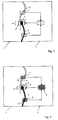
- two workpieces 1 and 2 are to be connected to one another by a beam 3.
- the area of the connection between the two workpieces 1 and 2 in front of the beam 3 is referred to as the joining line 4, the area after the beam 3 as the weld seam 5.
- the beam 3 comes from a beam source (not shown in more detail) on a displacement device 6, which can consist, for example, of a cross slide.
- the displacement device 6 can be displaced two-dimensionally in the x or y direction.
- three-dimensional displaceability is also conceivable. The only essential thing is that the displacement device 6 allows the beam 3 to be guided along the joining line 4 and aligned with it.
- the beam 3 is preceded by a sensor 7, which is also referred to as a seam search system.
- a sensor 7 With this sensor 7, the course of the joining line 4 is continuously determined and the course of the joining line 4 via a control unit 8 on the basis of the speed-dependent displacement time of the workpieces - or the displacement time of the beam if this is shifted relative to the workpieces determined, this control unit 8 sets the displacement device 6 in accordance with the measurement results of the sensor 7 in motion, so that the beam 3 is always directed exactly at the joining line 4, preferably at a center line of the joining line 4, not shown in detail.
- the beam 3 is to be followed by a further sensor 9, which is also connected to the control unit 8.
- This second sensor 9 monitors the weld seam 5.
- the sensor 7, which leads the beam 3, works in the so-called light section method.
- a stripe pattern in the present case consisting of five parallel stripes 10, is projected onto the area of the joining line 4 at an angle to the optical axis of the sensor optics.
- the strips 10 run essentially transversely to the weld seam, but can also be spaced differently.
- the strips are interrupted in the area of the joining line 4 or dislocations take place which are recognized by the sensor optics.
- a course of the joining lines can then be determined on the basis of a number of points corresponding to the number of strips.
- the second sensor 9 also works according to the same principle, with the weld seam 5 being illuminated with a corresponding stripe pattern 11 here.
- the beam 3 deviates from its position shown in solid lines to a position indicated by the broken line, for example due to a thermally induced drift, this cannot be determined by the sensor 7, since this sensor 7 always assumes that the beam 3 is in the basic position.
- the subsequent sensor 9 determines a course of the weld seam 5 which differs from the sensor 7, since the measurement results fed to the control unit 8, which consist, for example, of position coordinates obtained by image analysis, no longer match. This is also indicated schematically in dashed lines.
- the displacement unit is now moved in accordance with the correction value obtained, so that the beam 3 is moved back into the basic position.
Landscapes
- Physics & Mathematics (AREA)
- Engineering & Computer Science (AREA)
- Optics & Photonics (AREA)
- Plasma & Fusion (AREA)
- Mechanical Engineering (AREA)
- General Physics & Mathematics (AREA)
- Laser Beam Processing (AREA)
- Length Measuring Devices By Optical Means (AREA)
- Sewing Machines And Sewing (AREA)
- Machine Tool Sensing Apparatuses (AREA)
- Welding Or Cutting Using Electron Beams (AREA)
Applications Claiming Priority (3)
| Application Number | Priority Date | Filing Date | Title |
|---|---|---|---|
| CH282395 | 1995-10-06 | ||
| CH2823/95 | 1995-10-06 | ||
| CH282395 | 1995-10-06 |
Publications (3)
| Publication Number | Publication Date |
|---|---|
| EP0770445A2 true EP0770445A2 (fr) | 1997-05-02 |
| EP0770445A3 EP0770445A3 (fr) | 1998-08-12 |
| EP0770445B1 EP0770445B1 (fr) | 2001-11-07 |
Family
ID=4242408
Family Applications (1)
| Application Number | Title | Priority Date | Filing Date |
|---|---|---|---|
| EP96112931A Expired - Lifetime EP0770445B1 (fr) | 1995-10-06 | 1996-08-12 | Méthode de contrôle et de positionnement d'un faisceau ou d'un jet pour l'usinage d'une pièce |
Country Status (15)
| Country | Link |
|---|---|
| US (1) | US5877960A (fr) |
| EP (1) | EP0770445B1 (fr) |
| JP (1) | JP2895448B2 (fr) |
| KR (1) | KR100420722B1 (fr) |
| CN (1) | CN1089284C (fr) |
| AR (1) | AR003737A1 (fr) |
| AT (1) | ATE208243T1 (fr) |
| BR (1) | BR9605006A (fr) |
| CA (1) | CA2183779C (fr) |
| DE (1) | DE59608130D1 (fr) |
| DK (1) | DK0770445T3 (fr) |
| FI (1) | FI963937A7 (fr) |
| NO (1) | NO964226L (fr) |
| PL (1) | PL180628B1 (fr) |
| RU (1) | RU2155654C2 (fr) |
Cited By (11)
| Publication number | Priority date | Publication date | Assignee | Title |
|---|---|---|---|---|
| DE102007030395A1 (de) * | 2007-06-29 | 2009-01-02 | Trumpf Werkzeugmaschinen Gmbh + Co. Kg | Verfahren und Vorrichtung zum Laserstrahlschweißen eines Werkstücks |
| EP2022595A1 (fr) * | 2007-07-23 | 2009-02-11 | Grünberger, Thomas | Procédé et dispositif de réglage d'une position de traitement |
| WO2010000529A1 (fr) * | 2008-07-02 | 2010-01-07 | Robert Bosch Gmbh | Appareil d'usinage motorisé |
| DE102009042986B3 (de) * | 2009-09-25 | 2011-03-03 | Precitec Kg | Schweißkopf und Verfahren zum Fügen eines Werkstücks |
| DE102010011253A1 (de) | 2010-03-12 | 2011-09-15 | Precitec Kg | Laserbearbeitungskopf und Verfahren zur Bearbeitung eines Werkstücks mittels eines Laserstrahls |
| WO2012116795A1 (fr) * | 2011-03-03 | 2012-09-07 | Brose Fahrzeugteile Gmbh & Co. Kommanditgesellschaft, Coburg | Procédé de surveillance d'un décalage latéral entre un tracé réel de joint de soudure et un tracé théorique de joint de soudure, ensemble et siège de véhicule automobile |
| DE102012204207A1 (de) | 2012-03-16 | 2013-09-19 | Trumpf Werkzeugmaschinen Gmbh + Co. Kg | Verfahren zum Laserstrahlschweißen |
| WO2014057290A1 (fr) * | 2012-10-12 | 2014-04-17 | Meta Vision Systems Limited | Procédés et systèmes de commande de soudage |
| DE102018008873A1 (de) | 2017-11-13 | 2019-05-16 | Matthias Sehrschön | Verfahren und eine Vorrichtung zum Bearbeiten eines Werkstücks mit einem Strahl |
| DE102018217919A1 (de) * | 2018-10-19 | 2020-04-23 | Trumpf Werkzeugmaschinen Gmbh + Co. Kg | Verfahren zum Ermitteln einer korrigierten Bearbeitungskopf-Position und Bearbeitungsmaschine |
| CN112935541A (zh) * | 2021-02-01 | 2021-06-11 | 西南石油大学 | 一种激光跟踪大型曲面板角焊系统及方法 |
Families Citing this family (27)
| Publication number | Priority date | Publication date | Assignee | Title |
|---|---|---|---|---|
| JPH09269808A (ja) * | 1996-03-29 | 1997-10-14 | Fanuc Ltd | Cncデータ補正方法 |
| US6230072B1 (en) * | 1998-02-09 | 2001-05-08 | John W. Powell | Boiler automated welding system (BAWS) |
| MXPA03003610A (es) * | 2000-10-24 | 2003-06-19 | Elpatronic Ag | Aparato y metodo para procesar piezas de trabajo. |
| US7081599B2 (en) | 2000-10-24 | 2006-07-25 | Elpatronic Ag | Apparatus and method for processing workpieces |
| JP3424001B2 (ja) * | 2000-12-28 | 2003-07-07 | 川崎重工業株式会社 | レーザ溶接方法およびレーザ溶接装置 |
| DE10111662A1 (de) * | 2001-03-09 | 2002-09-26 | Thyssenkrupp Stahl Ag | Verfahren und Vorrichtung zum robotergesteuerten Schneiden und Schweißen mit Laserstrahlung |
| US6766216B2 (en) * | 2001-08-27 | 2004-07-20 | Flow International Corporation | Method and system for automated software control of waterjet orientation parameters |
| CA2465231C (fr) * | 2001-11-15 | 2011-08-09 | Elpatronic Ag | Procede et dispositif pour evaluer des points de jonction de pieces |
| RU2230538C1 (ru) * | 2002-12-26 | 2004-06-20 | Центр физического приборостроения ИОФ РАН | Способ и установка лазерной коррекции роговицы глаза |
| AT412456B (de) * | 2003-04-07 | 2005-03-25 | Fronius Int Gmbh | Nahtverfolgungssensor |
| CA2463409A1 (fr) | 2004-04-02 | 2005-10-02 | Servo-Robot Inc. | Tete intelligente de liaison a un laser |
| EP1632305A1 (fr) * | 2004-09-04 | 2006-03-08 | Trumpf Werkzeugmaschinen GmbH + Co. KG | Procédé pour déterminer et procédé de réglage de la position réciproque de l'axe d'un faisceau laser d'usinage et de l'axe d'un jet de gaz de traitement sur une machine d'usinage ainsi que machine d'usinage avec les équipements pour exécuter lesdits procédés |
| CN100341658C (zh) * | 2005-07-04 | 2007-10-10 | 中国航空工业第一集团公司北京航空制造工程研究所 | 一种高能束流焊接过程多信号融合监测仪 |
| JP2009083022A (ja) * | 2007-09-28 | 2009-04-23 | Sugino Mach Ltd | 噴流加工装置、および噴流加工装置における原点補正方法 |
| EP2062674B1 (fr) | 2007-11-20 | 2016-11-02 | TRUMPF Werkzeugmaschinen GmbH + Co. KG | Procédé de préparation et de réalisation d'un processus de soudure laser |
| US8600552B2 (en) | 2009-10-30 | 2013-12-03 | Honda Motor Co., Ltd. | Information processing method, apparatus, and computer readable medium |
| US8716627B2 (en) * | 2010-09-10 | 2014-05-06 | Honeywell International Inc. | Welding systems and methods |
| US9003936B2 (en) | 2011-07-29 | 2015-04-14 | Flow International Corporation | Waterjet cutting system with standoff distance control |
| RU2495737C1 (ru) * | 2012-02-21 | 2013-10-20 | Федеральное государственное унитарное предприятие "Российский федеральный ядерный центр - Всероссийский научно-исследовательский институт технической физики имени академика Е.И. Забабахина" | Способ контроля электронно-лучевой сварки |
| US9884406B2 (en) | 2014-01-15 | 2018-02-06 | Flow International Corporation | High-pressure waterjet cutting head systems, components and related methods |
| US10596717B2 (en) | 2015-07-13 | 2020-03-24 | Flow International Corporation | Methods of cutting fiber reinforced polymer composite workpieces with a pure waterjet |
| PL3292947T3 (pl) | 2016-09-07 | 2022-08-08 | Water Jet Sweden Ab | Maszyna i metoda cięcia fluid jet |
| JP6831302B2 (ja) | 2017-06-21 | 2021-02-17 | トヨタ自動車株式会社 | レーザ加工品の製造方法および電池の製造方法 |
| CN113056345B (zh) * | 2018-09-28 | 2024-01-02 | 康宁股份有限公司 | 用于对透明基板改性的系统和方法 |
| DE102018217487A1 (de) * | 2018-10-12 | 2020-04-16 | Trumpf Werkzeugmaschinen Gmbh + Co. Kg | Maschine zum trennenden Bearbeiten eines plattenförmigen Werkstücks |
| CN110773858A (zh) * | 2019-11-20 | 2020-02-11 | 桂林航天工业学院 | 一种电子束焊接装置及焊接方法 |
| RU2763706C1 (ru) * | 2021-03-16 | 2021-12-30 | федеральное государственное бюджетное образовательное учреждение высшего образования "Казанский национальный исследовательский технический университет им.А.Н. Туполева - КАИ" | Способ лазерной сварки разнородных металлических сплавов |
Family Cites Families (19)
| Publication number | Priority date | Publication date | Assignee | Title |
|---|---|---|---|---|
| DE2608720A1 (de) * | 1976-03-03 | 1977-09-08 | Fritz Richter | Beruehrungslose schweissnahtabtastung |
| US4199674A (en) * | 1978-12-26 | 1980-04-22 | Butler Manufacturing Company | Weld head control and guidance system |
| JPS56122673A (en) * | 1980-03-04 | 1981-09-26 | Shin Meiwa Ind Co Ltd | Location detecting sensor of groove welding line |
| JPS58107273A (ja) * | 1981-12-18 | 1983-06-25 | Japan Steel & Tube Constr Co Ltd | 溶接ア−ク検出方法及び装置 |
| US4571479A (en) * | 1983-03-14 | 1986-02-18 | Mitsubishi Denki Kabushiki Kaisha | Welding machine with automatic seam tracking |
| FR2559695B1 (fr) * | 1984-02-20 | 1995-04-21 | Mitsubishi Electric Corp | Procede et appareil pour detecter et reguler la position d'un faisceau electronique de soudage |
| US4588872A (en) * | 1984-03-22 | 1986-05-13 | Bollinger John G | Self-guided welding machine |
| JPS62114787A (ja) * | 1985-11-13 | 1987-05-26 | Toyota Motor Corp | 溶接位置補正装置付レ−ザ−溶接装置 |
| DE3632952A1 (de) * | 1986-09-27 | 1988-04-07 | Hoesch Ag | Verfahren und vorrichtung zur kontinuierlichen herstellung rohrfoermiger koerper mittels laser-laengsnahtschweissung |
| JP2716052B2 (ja) * | 1987-01-13 | 1998-02-18 | 株式会社日立製作所 | 加工方法及び装置並びに加工品質管理方法 |
| US4907169A (en) * | 1987-09-30 | 1990-03-06 | International Technical Associates | Adaptive tracking vision and guidance system |
| US4843287A (en) * | 1987-12-31 | 1989-06-27 | Westinghouse Electric Corp. | Path contriving system for look-ahead sensor in a robotic control system |
| DE3801626C1 (en) * | 1988-01-21 | 1988-12-29 | Daimler-Benz Ag, 7000 Stuttgart, De | Rotating circular scanner, working according to the triangulation principle, as optical seam position sensor for a welding torch |
| DE3830892C1 (fr) * | 1988-09-10 | 1989-09-28 | Fried. Krupp Gmbh, 4300 Essen, De | |
| FR2636874B1 (fr) * | 1988-09-23 | 1994-07-08 | Sommeria Klein Jean | Procede et dispositif pour le controle et la commande automatiques du soudage de bandes en continu |
| US4831233A (en) * | 1988-09-28 | 1989-05-16 | The United States Of America As Represented By The Administrator Of The National Aeronautics And Space Administration | Optically controlled welding system |
| GB9126765D0 (en) * | 1991-12-17 | 1992-02-12 | Rolls Royce Plc | Electron beam welding |
| JPH05293648A (ja) * | 1992-04-21 | 1993-11-09 | Kawasaki Steel Corp | アーク溶接用直視モニタ |
| DE4312241A1 (de) * | 1993-04-15 | 1994-10-20 | Deutsche Aerospace | Verfahren zur Nahtvermessung |
-
1996
- 1996-08-12 DK DK96112931T patent/DK0770445T3/da active
- 1996-08-12 AT AT96112931T patent/ATE208243T1/de active
- 1996-08-12 EP EP96112931A patent/EP0770445B1/fr not_active Expired - Lifetime
- 1996-08-12 DE DE59608130T patent/DE59608130D1/de not_active Expired - Lifetime
- 1996-08-20 CA CA002183779A patent/CA2183779C/fr not_active Expired - Lifetime
- 1996-08-29 US US08/706,403 patent/US5877960A/en not_active Expired - Lifetime
- 1996-09-11 RU RU96117980/02A patent/RU2155654C2/ru not_active IP Right Cessation
- 1996-09-27 AR ARP960104529A patent/AR003737A1/es unknown
- 1996-10-01 KR KR1019960043430A patent/KR100420722B1/ko not_active Expired - Lifetime
- 1996-10-02 JP JP8262077A patent/JP2895448B2/ja not_active Expired - Lifetime
- 1996-10-02 FI FI963937A patent/FI963937A7/fi not_active Application Discontinuation
- 1996-10-04 BR BR9605006A patent/BR9605006A/pt not_active IP Right Cessation
- 1996-10-04 PL PL96316402A patent/PL180628B1/pl unknown
- 1996-10-04 CN CN96112721A patent/CN1089284C/zh not_active Expired - Lifetime
- 1996-10-04 NO NO964226A patent/NO964226L/no not_active Application Discontinuation
Cited By (19)
| Publication number | Priority date | Publication date | Assignee | Title |
|---|---|---|---|---|
| DE102007030395B4 (de) * | 2007-06-29 | 2010-09-30 | Trumpf Werkzeugmaschinen Gmbh + Co. Kg | Verfahren und Vorrichtung zum Laserstrahlschweißen eines Werkstücks |
| DE102007030395A1 (de) * | 2007-06-29 | 2009-01-02 | Trumpf Werkzeugmaschinen Gmbh + Co. Kg | Verfahren und Vorrichtung zum Laserstrahlschweißen eines Werkstücks |
| EP2022595A1 (fr) * | 2007-07-23 | 2009-02-11 | Grünberger, Thomas | Procédé et dispositif de réglage d'une position de traitement |
| WO2010000529A1 (fr) * | 2008-07-02 | 2010-01-07 | Robert Bosch Gmbh | Appareil d'usinage motorisé |
| DE102009042986B3 (de) * | 2009-09-25 | 2011-03-03 | Precitec Kg | Schweißkopf und Verfahren zum Fügen eines Werkstücks |
| WO2011035913A1 (fr) | 2009-09-25 | 2011-03-31 | Precitec Kg | Tête de soudage et procédé de jonction d'une pièce |
| US10092977B2 (en) | 2009-09-25 | 2018-10-09 | Precitec Gmbh & Co. Kg | Welding head and method for joining a workpiece |
| US9259801B2 (en) | 2010-03-12 | 2016-02-16 | Precitec Kg | Laser processing head and method for processing a workpiece by means of a laser beam |
| DE102010011253A1 (de) | 2010-03-12 | 2011-09-15 | Precitec Kg | Laserbearbeitungskopf und Verfahren zur Bearbeitung eines Werkstücks mittels eines Laserstrahls |
| WO2011110357A1 (fr) | 2010-03-12 | 2011-09-15 | Precitec Kg | Tête d'usinage au laser et procédé pour l'usinage d'une pièce au moyen d'un faisceau laser |
| DE102010011253B4 (de) * | 2010-03-12 | 2013-07-11 | Precitec Kg | Laserbearbeitungskopf, Robotervorrichtung und Verfahren zur Bearbeitung eines Werkstücks mittels eines Laserstrahls |
| WO2012116795A1 (fr) * | 2011-03-03 | 2012-09-07 | Brose Fahrzeugteile Gmbh & Co. Kommanditgesellschaft, Coburg | Procédé de surveillance d'un décalage latéral entre un tracé réel de joint de soudure et un tracé théorique de joint de soudure, ensemble et siège de véhicule automobile |
| US9649726B2 (en) | 2011-03-03 | 2017-05-16 | Brose Fahrzeugteile Gmbh & Co., Kommanditgesellschaft, Coburg | Method for monitoring a lateral offset of an actual weld seam configuration relative to a desired weld seam configuration, assembly and motor vehicle seat |
| DE102012204207B4 (de) * | 2012-03-16 | 2015-02-19 | Trumpf Werkzeugmaschinen Gmbh + Co. Kg | Verfahren zum Laserstrahlschweißen |
| DE102012204207A1 (de) | 2012-03-16 | 2013-09-19 | Trumpf Werkzeugmaschinen Gmbh + Co. Kg | Verfahren zum Laserstrahlschweißen |
| WO2014057290A1 (fr) * | 2012-10-12 | 2014-04-17 | Meta Vision Systems Limited | Procédés et systèmes de commande de soudage |
| DE102018008873A1 (de) | 2017-11-13 | 2019-05-16 | Matthias Sehrschön | Verfahren und eine Vorrichtung zum Bearbeiten eines Werkstücks mit einem Strahl |
| DE102018217919A1 (de) * | 2018-10-19 | 2020-04-23 | Trumpf Werkzeugmaschinen Gmbh + Co. Kg | Verfahren zum Ermitteln einer korrigierten Bearbeitungskopf-Position und Bearbeitungsmaschine |
| CN112935541A (zh) * | 2021-02-01 | 2021-06-11 | 西南石油大学 | 一种激光跟踪大型曲面板角焊系统及方法 |
Also Published As
| Publication number | Publication date |
|---|---|
| JP2895448B2 (ja) | 1999-05-24 |
| RU2155654C2 (ru) | 2000-09-10 |
| DE59608130D1 (de) | 2001-12-13 |
| CA2183779C (fr) | 2007-06-19 |
| EP0770445B1 (fr) | 2001-11-07 |
| PL316402A1 (en) | 1997-04-14 |
| NO964226L (no) | 1997-04-07 |
| BR9605006A (pt) | 1998-06-23 |
| CA2183779A1 (fr) | 1997-04-07 |
| FI963937A7 (fi) | 1997-04-07 |
| JPH09126726A (ja) | 1997-05-16 |
| NO964226D0 (no) | 1996-10-04 |
| AR003737A1 (es) | 1998-09-09 |
| KR970022336A (ko) | 1997-05-28 |
| US5877960A (en) | 1999-03-02 |
| MX9604523A (es) | 1997-07-31 |
| CN1154283A (zh) | 1997-07-16 |
| CN1089284C (zh) | 2002-08-21 |
| FI963937A0 (fi) | 1996-10-02 |
| DK0770445T3 (da) | 2002-02-18 |
| EP0770445A3 (fr) | 1998-08-12 |
| KR100420722B1 (ko) | 2004-05-24 |
| ATE208243T1 (de) | 2001-11-15 |
| PL180628B1 (pl) | 2001-03-30 |
Similar Documents
| Publication | Publication Date | Title |
|---|---|---|
| EP0770445B1 (fr) | Méthode de contrôle et de positionnement d'un faisceau ou d'un jet pour l'usinage d'une pièce | |
| DE102013219220B4 (de) | Verfahren zum Laser- Remote Bearbeiten eines Werkstücks an einer Kehle und Vorrichtung hierfür | |
| EP3710196B1 (fr) | Système d'usinage au laser et procédé d'usinage au laser | |
| EP2544849B1 (fr) | Tête de travail au laser et procédé de travail au laser | |
| EP1979124B1 (fr) | Tete de soudage a faisceau laser, son utilisation et méthode de soudage par faisceau | |
| DE102016014564B4 (de) | Messvorrichtung zum Überwachen eines Bearbeitungsprozesses unter Verwendung von an unterschiedlichen Messpositionen erfassten Messinformationen | |
| EP0367924B1 (fr) | Procédé et dispositif pour déterminer la position d'un joint d'une soudure pour le soudage à laser | |
| EP1904260B1 (fr) | Procede et dispositif pour determiner un mouvement relatif lateral entre une tete d'usinage et une piece | |
| DE102016118189B4 (de) | Verfahren und Laserbearbeitungsmaschine zum Laserschweißen eines ersten und eines zweiten Werkstückabschnitts | |
| DE102017115922B4 (de) | Verfahren und Vorrichtung zur Messung und Einstellung eines Abstands zwischen einem Bearbeitungskopf und einem Werkstück sowie dazugehöriges Verfahren zur Regelung | |
| DE102015015330B4 (de) | Bearbeitungsvorrichtung und Verfahren zum Überwachen eines mit einer Bearbeitungsvorrichtung ausgeführten Bearbeitungsprozesses | |
| DE102017215973A1 (de) | Vorrichtung und Verfahren zur Bestimmung der Strahllage eines Laserstrahls | |
| DE102010005896A1 (de) | Laserschweißroboter und -verfahren sowie damit hergestelltes Bauteil | |
| EP2418040B1 (fr) | Procédé de contrôle d'un dispositif de soudure par laser | |
| DE102017010055A1 (de) | Laserstrahlschweißen von geometrischen Figuren mit OCT-Nahtführung | |
| EP1238746A2 (fr) | Méthode et appareil de découpe et soudage laser à commande robotique | |
| EP2131145A1 (fr) | Dispositif de surveillance optique | |
| WO2023138960A1 (fr) | Procédé de détermination d'une grandeur de résultat géométrique et/ou d'une caractéristique de qualité d'un cordon de soudure sur une pièce, et dispositif correspondant | |
| DE4026759A1 (de) | Mit schweissstossverfolgung arbeitendes laserschweisssystem | |
| DE202014105648U1 (de) | Vorrichtung zum Fügen von Werkstücken an einem Überlappungsstoß | |
| AT522419B1 (de) | Messvorrichtung zur Bestimmung des Biegewinkels | |
| DE102015115803A1 (de) | Verfahren zum Führen eines Bearbeitungskopfes entlang einer zu bearbeitenden Spur | |
| EP2874778A1 (fr) | Procédé et dispositif de mesure de distance sans contact | |
| EP1399287B1 (fr) | Procede de coupe au rayonnement laser de pieces a assembler | |
| DE102022104804A1 (de) | Verfahren und Vorrichtung zum Bearbeiten von Werkstücken mit einer automatischen Lageerfassung der Werkstücke |
Legal Events
| Date | Code | Title | Description |
|---|---|---|---|
| PUAI | Public reference made under article 153(3) epc to a published international application that has entered the european phase |
Free format text: ORIGINAL CODE: 0009012 |
|
| AK | Designated contracting states |
Kind code of ref document: A2 Designated state(s): AT BE CH DE DK LI NL SE |
|
| PUAL | Search report despatched |
Free format text: ORIGINAL CODE: 0009013 |
|
| AK | Designated contracting states |
Kind code of ref document: A3 Designated state(s): AT BE CH DE DK LI NL SE |
|
| 17P | Request for examination filed |
Effective date: 19990212 |
|
| RAP3 | Party data changed (applicant data changed or rights of an application transferred) |
Owner name: ELPATRONIC AG |
|
| GRAG | Despatch of communication of intention to grant |
Free format text: ORIGINAL CODE: EPIDOS AGRA |
|
| 17Q | First examination report despatched |
Effective date: 20010125 |
|
| GRAG | Despatch of communication of intention to grant |
Free format text: ORIGINAL CODE: EPIDOS AGRA |
|
| GRAH | Despatch of communication of intention to grant a patent |
Free format text: ORIGINAL CODE: EPIDOS IGRA |
|
| GRAH | Despatch of communication of intention to grant a patent |
Free format text: ORIGINAL CODE: EPIDOS IGRA |
|
| GRAA | (expected) grant |
Free format text: ORIGINAL CODE: 0009210 |
|
| AK | Designated contracting states |
Kind code of ref document: B1 Designated state(s): AT BE CH DE DK LI NL SE |
|
| REF | Corresponds to: |
Ref document number: 208243 Country of ref document: AT Date of ref document: 20011115 Kind code of ref document: T |
|
| REG | Reference to a national code |
Ref country code: CH Ref legal event code: EP |
|
| REF | Corresponds to: |
Ref document number: 59608130 Country of ref document: DE Date of ref document: 20011213 |
|
| REG | Reference to a national code |
Ref country code: DK Ref legal event code: T3 |
|
| PLBE | No opposition filed within time limit |
Free format text: ORIGINAL CODE: 0009261 |
|
| STAA | Information on the status of an ep patent application or granted ep patent |
Free format text: STATUS: NO OPPOSITION FILED WITHIN TIME LIMIT |
|
| 26N | No opposition filed | ||
| PGFP | Annual fee paid to national office [announced via postgrant information from national office to epo] |
Ref country code: NL Payment date: 20080813 Year of fee payment: 13 Ref country code: DK Payment date: 20080814 Year of fee payment: 13 |
|
| REG | Reference to a national code |
Ref country code: CH Ref legal event code: PUE Owner name: PRECITEC VISION GMBH & CO. KG Free format text: SOUTEC SOUDRONIC AG#ROTFARB 3#8413 NEFTENBACH (CH) -TRANSFER TO- PRECITEC VISION GMBH & CO. KG#UNTERORTSTRASSE 48#65760 ESCHBORN (DE) Ref country code: CH Ref legal event code: PUE Owner name: SOUDRONIC AG Free format text: ELPATRONIC AG#INDUSTRIESTRASSE 35#8962 BERGDIETIKON (CH) -TRANSFER TO- SOUDRONIC AG#INDUSTRIESTRASSE 35#8962 BERGDIETIKON (CH) Ref country code: CH Ref legal event code: PUE Owner name: SOUTEC SOUDRONIC AG Free format text: SOUDRONIC AG#INDUSTRIESTRASSE 35#8962 BERGDIETIKON (CH) -TRANSFER TO- SOUTEC SOUDRONIC AG#ROTFARB 3#8413 NEFTENBACH (CH) Ref country code: CH Ref legal event code: NV Representative=s name: E. BLUM & CO. AG PATENT- UND MARKENANWAELTE VSP |
|
| PGFP | Annual fee paid to national office [announced via postgrant information from national office to epo] |
Ref country code: BE Payment date: 20080918 Year of fee payment: 13 |
|
| BECA | Be: change of holder's address |
Owner name: PRECITEC VISION G.M.B.H. & CO. K.G.UNTERORTSTRASSE Effective date: 20090219 |
|
| BECH | Be: change of holder |
Owner name: PRECITEC VISION G.M.B.H. & CO. K.G.UNTERORTSTRASSE Effective date: 20090219 Owner name: PRECITEC VISION G.M.B.H. & CO. K.G. Effective date: 20090219 |
|
| BERE | Be: lapsed |
Owner name: PRECITEC VISION G.M.B.H. & CO. K.G. Effective date: 20090831 |
|
| REG | Reference to a national code |
Ref country code: NL Ref legal event code: V1 Effective date: 20100301 Ref country code: CH Ref legal event code: NV Representative=s name: BOHEST AG |
|
| REG | Reference to a national code |
Ref country code: DK Ref legal event code: EBP |
|
| PG25 | Lapsed in a contracting state [announced via postgrant information from national office to epo] |
Ref country code: BE Free format text: LAPSE BECAUSE OF NON-PAYMENT OF DUE FEES Effective date: 20090831 |
|
| PG25 | Lapsed in a contracting state [announced via postgrant information from national office to epo] |
Ref country code: NL Free format text: LAPSE BECAUSE OF NON-PAYMENT OF DUE FEES Effective date: 20100301 Ref country code: DK Free format text: LAPSE BECAUSE OF NON-PAYMENT OF DUE FEES Effective date: 20090831 |
|
| REG | Reference to a national code |
Ref country code: CH Ref legal event code: PCAR Free format text: NEW ADDRESS: HOLBEINSTRASSE 36-38, 4051 BASEL (CH) |
|
| PGFP | Annual fee paid to national office [announced via postgrant information from national office to epo] |
Ref country code: CH Payment date: 20150824 Year of fee payment: 20 Ref country code: DE Payment date: 20150825 Year of fee payment: 20 |
|
| PGFP | Annual fee paid to national office [announced via postgrant information from national office to epo] |
Ref country code: SE Payment date: 20150824 Year of fee payment: 20 Ref country code: AT Payment date: 20150820 Year of fee payment: 20 |
|
| REG | Reference to a national code |
Ref country code: DE Ref legal event code: R071 Ref document number: 59608130 Country of ref document: DE |
|
| REG | Reference to a national code |
Ref country code: CH Ref legal event code: PL |
|
| REG | Reference to a national code |
Ref country code: SE Ref legal event code: EUG |
|
| REG | Reference to a national code |
Ref country code: AT Ref legal event code: MK07 Ref document number: 208243 Country of ref document: AT Kind code of ref document: T Effective date: 20160812 |