EP3710196B1 - Système d'usinage au laser et procédé d'usinage au laser - Google Patents
Système d'usinage au laser et procédé d'usinage au laser Download PDFInfo
- Publication number
- EP3710196B1 EP3710196B1 EP18789601.4A EP18789601A EP3710196B1 EP 3710196 B1 EP3710196 B1 EP 3710196B1 EP 18789601 A EP18789601 A EP 18789601A EP 3710196 B1 EP3710196 B1 EP 3710196B1
- Authority
- EP
- European Patent Office
- Prior art keywords
- laser
- machining
- laser beam
- seam
- measuring
- Prior art date
- Legal status (The legal status is an assumption and is not a legal conclusion. Google has not performed a legal analysis and makes no representation as to the accuracy of the status listed.)
- Active
Links
Images


Classifications
-
- G—PHYSICS
- G01—MEASURING; TESTING
- G01B—MEASURING LENGTH, THICKNESS OR SIMILAR LINEAR DIMENSIONS; MEASURING ANGLES; MEASURING AREAS; MEASURING IRREGULARITIES OF SURFACES OR CONTOURS
- G01B9/00—Measuring instruments characterised by the use of optical techniques
- G01B9/02—Interferometers
- G01B9/0209—Low-coherence interferometers
- G01B9/02091—Tomographic interferometers, e.g. based on optical coherence
-
- B—PERFORMING OPERATIONS; TRANSPORTING
- B23—MACHINE TOOLS; METAL-WORKING NOT OTHERWISE PROVIDED FOR
- B23K—SOLDERING OR UNSOLDERING; WELDING; CLADDING OR PLATING BY SOLDERING OR WELDING; CUTTING BY APPLYING HEAT LOCALLY, e.g. FLAME CUTTING; WORKING BY LASER BEAM
- B23K26/00—Working by laser beam, e.g. welding, cutting or boring
- B23K26/02—Positioning or observing the workpiece, e.g. with respect to the point of impact; Aligning, aiming or focusing the laser beam
- B23K26/03—Observing, e.g. monitoring, the workpiece
- B23K26/032—Observing, e.g. monitoring, the workpiece using optical means
-
- B—PERFORMING OPERATIONS; TRANSPORTING
- B23—MACHINE TOOLS; METAL-WORKING NOT OTHERWISE PROVIDED FOR
- B23K—SOLDERING OR UNSOLDERING; WELDING; CLADDING OR PLATING BY SOLDERING OR WELDING; CUTTING BY APPLYING HEAT LOCALLY, e.g. FLAME CUTTING; WORKING BY LASER BEAM
- B23K26/00—Working by laser beam, e.g. welding, cutting or boring
- B23K26/02—Positioning or observing the workpiece, e.g. with respect to the point of impact; Aligning, aiming or focusing the laser beam
- B23K26/04—Automatically aligning, aiming or focusing the laser beam, e.g. using the back-scattered light
- B23K26/044—Seam tracking
-
- B—PERFORMING OPERATIONS; TRANSPORTING
- B23—MACHINE TOOLS; METAL-WORKING NOT OTHERWISE PROVIDED FOR
- B23K—SOLDERING OR UNSOLDERING; WELDING; CLADDING OR PLATING BY SOLDERING OR WELDING; CUTTING BY APPLYING HEAT LOCALLY, e.g. FLAME CUTTING; WORKING BY LASER BEAM
- B23K26/00—Working by laser beam, e.g. welding, cutting or boring
- B23K26/02—Positioning or observing the workpiece, e.g. with respect to the point of impact; Aligning, aiming or focusing the laser beam
- B23K26/06—Shaping the laser beam, e.g. by masks or multi-focusing
- B23K26/064—Shaping the laser beam, e.g. by masks or multi-focusing by means of optical elements, e.g. lenses, mirrors or prisms
- B23K26/0643—Shaping the laser beam, e.g. by masks or multi-focusing by means of optical elements, e.g. lenses, mirrors or prisms comprising mirrors
-
- B—PERFORMING OPERATIONS; TRANSPORTING
- B23—MACHINE TOOLS; METAL-WORKING NOT OTHERWISE PROVIDED FOR
- B23K—SOLDERING OR UNSOLDERING; WELDING; CLADDING OR PLATING BY SOLDERING OR WELDING; CUTTING BY APPLYING HEAT LOCALLY, e.g. FLAME CUTTING; WORKING BY LASER BEAM
- B23K26/00—Working by laser beam, e.g. welding, cutting or boring
- B23K26/02—Positioning or observing the workpiece, e.g. with respect to the point of impact; Aligning, aiming or focusing the laser beam
- B23K26/06—Shaping the laser beam, e.g. by masks or multi-focusing
- B23K26/064—Shaping the laser beam, e.g. by masks or multi-focusing by means of optical elements, e.g. lenses, mirrors or prisms
- B23K26/0648—Shaping the laser beam, e.g. by masks or multi-focusing by means of optical elements, e.g. lenses, mirrors or prisms comprising lenses
-
- B—PERFORMING OPERATIONS; TRANSPORTING
- B23—MACHINE TOOLS; METAL-WORKING NOT OTHERWISE PROVIDED FOR
- B23K—SOLDERING OR UNSOLDERING; WELDING; CLADDING OR PLATING BY SOLDERING OR WELDING; CUTTING BY APPLYING HEAT LOCALLY, e.g. FLAME CUTTING; WORKING BY LASER BEAM
- B23K26/00—Working by laser beam, e.g. welding, cutting or boring
- B23K26/02—Positioning or observing the workpiece, e.g. with respect to the point of impact; Aligning, aiming or focusing the laser beam
- B23K26/06—Shaping the laser beam, e.g. by masks or multi-focusing
- B23K26/064—Shaping the laser beam, e.g. by masks or multi-focusing by means of optical elements, e.g. lenses, mirrors or prisms
- B23K26/0652—Shaping the laser beam, e.g. by masks or multi-focusing by means of optical elements, e.g. lenses, mirrors or prisms comprising prisms
-
- B—PERFORMING OPERATIONS; TRANSPORTING
- B23—MACHINE TOOLS; METAL-WORKING NOT OTHERWISE PROVIDED FOR
- B23K—SOLDERING OR UNSOLDERING; WELDING; CLADDING OR PLATING BY SOLDERING OR WELDING; CUTTING BY APPLYING HEAT LOCALLY, e.g. FLAME CUTTING; WORKING BY LASER BEAM
- B23K26/00—Working by laser beam, e.g. welding, cutting or boring
- B23K26/02—Positioning or observing the workpiece, e.g. with respect to the point of impact; Aligning, aiming or focusing the laser beam
- B23K26/06—Shaping the laser beam, e.g. by masks or multi-focusing
- B23K26/067—Dividing the beam into multiple beams, e.g. multi-focusing
-
- B—PERFORMING OPERATIONS; TRANSPORTING
- B23—MACHINE TOOLS; METAL-WORKING NOT OTHERWISE PROVIDED FOR
- B23K—SOLDERING OR UNSOLDERING; WELDING; CLADDING OR PLATING BY SOLDERING OR WELDING; CUTTING BY APPLYING HEAT LOCALLY, e.g. FLAME CUTTING; WORKING BY LASER BEAM
- B23K26/00—Working by laser beam, e.g. welding, cutting or boring
- B23K26/08—Devices involving relative movement between laser beam and workpiece
- B23K26/082—Scanning systems, i.e. devices involving movement of the laser beam relative to the laser head
-
- B—PERFORMING OPERATIONS; TRANSPORTING
- B23—MACHINE TOOLS; METAL-WORKING NOT OTHERWISE PROVIDED FOR
- B23K—SOLDERING OR UNSOLDERING; WELDING; CLADDING OR PLATING BY SOLDERING OR WELDING; CUTTING BY APPLYING HEAT LOCALLY, e.g. FLAME CUTTING; WORKING BY LASER BEAM
- B23K26/00—Working by laser beam, e.g. welding, cutting or boring
- B23K26/20—Bonding
- B23K26/21—Bonding by welding
- B23K26/24—Seam welding
- B23K26/28—Seam welding of curved planar seams
-
- B—PERFORMING OPERATIONS; TRANSPORTING
- B23—MACHINE TOOLS; METAL-WORKING NOT OTHERWISE PROVIDED FOR
- B23K—SOLDERING OR UNSOLDERING; WELDING; CLADDING OR PLATING BY SOLDERING OR WELDING; CUTTING BY APPLYING HEAT LOCALLY, e.g. FLAME CUTTING; WORKING BY LASER BEAM
- B23K31/00—Processes relevant to this subclass, specially adapted for particular articles or purposes, but not covered by any single one of main groups B23K1/00 - B23K28/00
- B23K31/12—Processes relevant to this subclass, specially adapted for particular articles or purposes, but not covered by any single one of main groups B23K1/00 - B23K28/00 relating to investigating the properties, e.g. the weldability, of materials
- B23K31/125—Weld quality monitoring
-
- G—PHYSICS
- G01—MEASURING; TESTING
- G01B—MEASURING LENGTH, THICKNESS OR SIMILAR LINEAR DIMENSIONS; MEASURING ANGLES; MEASURING AREAS; MEASURING IRREGULARITIES OF SURFACES OR CONTOURS
- G01B2290/00—Aspects of interferometers not specifically covered by any group under G01B9/02
- G01B2290/65—Spatial scanning object beam
Definitions
- the present disclosure relates to a laser processing system, in particular a system for material processing by means of a laser beam, such as a laser processing head for laser welding or laser cutting, and a method for laser processing.
- a laser processing system in particular a system for material processing by means of a laser beam, such as a laser processing head for laser welding or laser cutting, and a method for laser processing.
- the present disclosure relates in particular to seam measurement and seam tracking, for example by means of optical coherence tomography.
- the laser beam emerging from a laser light source is focused on the workpiece to be processed with the aid of beam guidance and focusing optics.
- a laser processing head with collimator optics and focusing optics is used as standard, the laser light being supplied via an optical fiber, also referred to as a laser source.
- the laser light passes through a large number of optical elements, such as lenses, in a device for processing materials by means of a laser, for example in a laser processing head.
- DE 10 2009 057 209 B4 is a device for material processing by means of laser with a scanner optics that can be moved by a guide machine relative to the workpiece to be processed.
- the device comprises a projector which is used to project measuring light in the form of measuring structures onto the workpiece to be processed, and an image sensor which is sensitive in the wavelength range of the measuring light emitted by the projector.
- the projector and the image sensor are connected to the scanner optics and are consequently moved along with the scanner optics when the device is operated. A direction-independent measurement is therefore not possible.
- a laser processing system comprises a first deflection optics which are set up to deflect a processing laser beam in two spatial directions, a second Deflection optics that are set up to deflect a measuring beam independently of the machining laser beam in two spatial directions, and a coupling device that is arranged in a beam path of the machining laser beam and is set up to couple the measuring beam into the beam path of the machining laser beam.
- the first deflecting optics preferably comprises two first deflecting mirrors that are independent of one another.
- the first deflection optics are typically set up for a two-dimensional oscillation of the processing laser beam, such as a movement along a line, preferably along a line perpendicular to the seam path, a circular movement or a movement in the form of an “8”.
- the second deflecting optics preferably comprises two second deflecting mirrors that are independent of one another.
- the second deflection optics is set up for a linear movement and / or a circular movement of the measuring beam.
- the second deflection optics are preferably set up to direct the measuring beam onto at least one workpiece, and in particular onto a joining area of two workpieces, independently of a feed direction of the machining laser beam.
- the coupling device is preferably a beam splitter.
- the coupling device is typically set up to superimpose the machining laser beam and the measuring beam essentially coaxially.
- the laser processing system preferably comprises a controller which is set up to control the first deflection device in such a way that the processing laser beam follows a seam path on the workpiece.
- the laser processing system preferably comprises an evaluation unit which is set up to measure a seam course, such as an edge course and / or a weld seam course, on the workpiece with the measuring beam.
- the evaluation unit can measure an edge profile of joining pieces before the machining laser beam and / or a weld seam profile after the machining laser beam.
- the evaluation unit can in particular be set up to determine the course of the seam by means of optical short coherence tomography.
- a method for laser machining comprises deflecting a machining laser beam in two spatial directions so that the machining laser beam executes a two-dimensional movement on at least one workpiece, deflecting a measuring beam in two spatial directions independently of the machining laser beam, and coupling the measuring beam into a beam path of the machining laser beam.
- the machining laser beam preferably executes an oscillating movement (2D wobbling process), such as, for example, a linear movement, a circular movement or a movement in the form of an “8”.
- 2D wobbling process such as, for example, a linear movement, a circular movement or a movement in the form of an “8”.
- the measuring beam preferably executes a linear or circular movement on the course of the seam, such as on an edge course and / or a weld seam course.
- the method preferably further comprises determining a seam course, such as an edge course of two workpieces to be joined, using the measuring beam, and following the seam course with the processing laser beam based on the determined seam course.
- a seam course such as an edge course of two workpieces to be joined
- Optical short coherence tomography is preferably used to determine the course of the seam.
- a direction-independent measurement of a seam course on a component and an exact positioning of the laser beam at the determined seam position are made possible in a laser machining process.
- An optical measuring beam is guided via its own actuator system and coupled into its beam path via a coupling device after the actuator system of a processing laser and superimposed on it.
- This arrangement enables a quasi-coaxial measurement of the component geometry around the current position of the machining laser beam, regardless of the movement of the machining laser beam during the machining process.
- Another advantage of the embodiments described here for finding seams compared to line projection in the light section method is the resolution that can be achieved.
- the embodiments described here in particular when using optical coherence tomography, offer an accuracy for the measured distance value of approximately 1 ⁇ m. Vertical structures on the component, such as the edge height of a fillet weld, can be measured with this accuracy.
- the resolution that can be achieved with a light section method is mainly limited by the quality of the line projection. Typical line widths are in the range from about 20 to 100 ⁇ m. As a result, the resolution of the structure recognition through the evaluation of the lines on the camera images is about an order of magnitude lower.
- Figure 1 shows a laser processing system 100, and in particular a system for material processing by means of a laser beam, for example for laser welding, according to embodiments of the present disclosure.
- the beam path of the machining laser is shown schematically, and on the right the beam path of the optical sensor system.
- the optical sensor system can be a coherence interferometer.
- the laser processing system 100 comprises first deflection optics 110, which are set up to deflect a machining laser beam 10 in two spatial directions x, y, a second deflection optics 120, which are set up to a measuring beam 15 (sensor beam) independently of the machining laser beam 10 in deflect two spatial directions x, y, and a coupling device 130 which is arranged in a beam path of the processing laser beam 10 and is set up to couple the measuring beam 15 into the beam path of the processing laser beam 10.
- the second deflection optics 120 is preferably set up to direct the measuring beam 15 onto at least one workpiece 1, and in particular onto a joining area of two workpieces, independently of a feed direction or machining direction 20 of the machining laser beam 10.
- a seam is found, for example, when welding components for precise positioning of the machining laser beam 10 relative to this seam.
- the measuring beam 15, which can be deflected in two directions by the second deflecting optics 120, enables the seam position to be determined independently of the current feed direction of a given machining process, such as a welding process, for example.
- a laser beam oscillation in two directions (“2D wobble process") can be carried out by means of its own actuator system in the beam path of the processing laser beam, which can be carried out independently of the movement of the measuring beam 15 in the measuring beam path.
- the laser processing system 100 (also referred to as “laser processing head”) comprises a laser source (not shown) for providing the processing laser beam, such as, for example, an optical fiber, as well as collimator optics 140, which are set up to collimate the processing laser beam 10, and a Focusing optics 150, which are set up to focus the machining laser beam 10 on at least one workpiece 1 or component.
- a laser source for providing the processing laser beam
- collimator optics 140 which are set up to collimate the processing laser beam 10
- Focusing optics 150 which are set up to focus the machining laser beam 10 on at least one workpiece 1 or component.
- the laser processing system 100 or parts thereof, such as, for example, a welding head, can, according to embodiments, be movable along the processing direction 20.
- the machining direction 20 can be a welding direction and / or a movement direction of the laser machining system 100, such as the welding head, with respect to the workpiece 1.
- the machining direction 20 can be a horizontal direction.
- the machining direction 20 can also be referred to as the “feed direction” or “process direction”.
- the laser processing system 100 is configured for welding.
- the laser processing system 100 can form a weld seam on a single workpiece, or can weld two workpieces (“joining pieces”) to one another, as in the example of FIG Figure 1 is shown.
- the laser processing system 100 can use the measuring beam 15 to measure a seam course, such as an edge course 2 and / or a weld seam course 3, on the workpiece 1.
- the edge profile 2 of joining pieces can be measured before the machining laser beam 10 and / or the weld seam profile 3 after the machining laser beam 10.
- the course of the seam can be measured or determined by means of the measuring beam 15 in the lead and / or in the wake of the machining laser beam 10.
- the laser processing system 100 preferably comprises an evaluation unit which is set up to measure the seam course, such as the edge course 2 and / or the weld seam course 3, on the workpiece with the measuring beam 15.
- the evaluation unit can measure or determine an edge profile of joining pieces with respect to the machining direction 20 in front of the machining laser beam 10 and / or a weld seam profile after the machining laser beam 10.
- the evaluation unit can, for example, in one optical coherence tomograph be included and evaluate the reflected measuring beam in order to determine the course of the seam.
- the laser processing system 100 typically comprises a controller which is set up to control the first deflection device 110 in such a way that the processing laser beam 10 follows the course of the seam on the workpiece.
- the controller can be connected to the evaluation unit and can receive data relating to the course of the seam from the evaluation unit.
- the controller can control the first deflection device 110 based on this data in such a way that the machining laser beam 10 follows the course of the seam on the workpiece.
- the laser processing system 100 is set up to deflect the processing laser beam 10 and the measuring beam 15 in two spatial directions x, y.
- the two spatial directions x, y can be directions of the Cartesian coordinate system, such as the X direction and the Y direction.
- the two spatial directions can be orthogonal to one another and span a plane.
- the coordinate system can be defined with respect to the workpiece and, in particular, can be fixed or stationary with respect to the workpiece.
- the coordinate system can be defined with respect to the part of the laser machining system 100 moving in the machining direction 20, such as the welding head, and can in particular be fixed or stationary with respect to the welding head.
- the first deflection optics 110 preferably comprises at least one first deflection mirror, and in particular two first deflection mirrors that are independent of one another.
- the independent first deflecting mirrors can be mounted rotatably about a respective axis of rotation in order to deflect the machining laser beam 10 in the two spatial directions.
- the axes of rotation can be perpendicular to one another and provide two degrees of freedom through which the machining laser beam 10 can be deflected two-dimensionally.
- the laser optics thus have an actuator, such as, for example, scanner optics, consisting of two independent scanning mirrors, by means of which the processing laser beam 10 can be deflected in two directions on the component.
- an actuator such as, for example, scanner optics, consisting of two independent scanning mirrors, by means of which the processing laser beam 10 can be deflected in two directions on the component.
- the first deflection optics 110 are set up for a two-dimensional oscillation of the machining laser beam 100.
- the machining laser beam 10 can oscillate in two directions during the process in order to specifically enlarge the area of influence of the machining laser beam 10 on the component and thereby achieve a more stable seam connection.
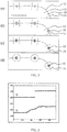
- the machining laser beam 10 can be deflected on a specific two-dimensional scan figure on the component, which, for example, consists of a line, a circle ( Figure 2 (a) ) or from the shape of an 8 ( Figures 2 (b) and (c) ) consists.
- the oscillation occurs at a frequency in the range from about 50 to 1000 Hz, and preferably at a frequency in the range from about 100 to 800 Hz.
- process variables such as laser speed, welding depth and seam width can be set in a targeted manner via the amplitude and the frequency of the movement.
- process variables such as laser speed, welding depth and seam width can be set in a targeted manner via the amplitude and the frequency of the movement.
- the amplitude of the laser oscillation by adapting the amplitude of the laser oscillation, the area of influence of the laser can be enlarged and, as a result, better gap bridging can be achieved.
- the mixing ratio in the melt can be set in a targeted manner by selecting the amplitude and frequency.
- the second deflection optics 120 comprises at least one second deflection mirror, and in particular two second deflection mirrors that are independent of one another.
- the independent second deflecting mirrors can be mounted rotatably about a respective axis of rotation in order to deflect the measuring beam 15 in the two spatial directions.
- the axes of rotation can be perpendicular to one another and provide two degrees of freedom through which the measuring beam 15 can be deflected two-dimensionally.
- the second deflection optics 120 is set up for a linear movement and / or a circular movement of the measuring beam, as described with reference to FIG Figure 2 is explained in more detail.
- the coupling device 130 is a beam splitter.
- the coupling-in device 130 is typically set up to superimpose the machining laser beam 10 and the measuring beam 15 essentially coaxially.
- the coupling device 130 can be arranged in front of the focusing optics 150, so that the processing laser beam 10 and the measuring beam 15 both pass through the focusing optics 150.
- the measuring light of the sensor system is coupled into the beam path of the processing laser, with the position of the measuring beam 15 on the component being able to be moved via a dedicated actuator or scanner unit.
- the sensor principle for distance measurement can, for example, be based on optical short-coherence interferometry (OCT).
- OCT optical short-coherence interferometry
- the coupling of the measuring beam 15 can take place via a beam splitter, which is located in the beam path of the hot laser beam after the actuator system of the processing laser.
- This arrangement achieves a quasi-coaxial superimposition of the measuring beam 15 and the machining laser beam 10, each of the two beams being able to be deflected in two directions independently of one another by its own actuator system.
- An essential advantage is that the component geometry can be measured around the current position of the machining laser beam 10 with the measuring beam 15, regardless of the movement of the machining laser beam 10 during the process.
- the measuring beam 15 can initially be moved repeatedly along a line which is located in front of the laser position in the welding direction in order to detect and set the exact position of the weld seam.
- the measuring beam 15 can then be moved repeatedly, for example, along a line that is located in the welding direction after the laser position in order to measure the seam geometry (see FIG Figures 1 and 2 (a) and (b) ).
- Another possible movement of the measuring beam 15 on the component is the repeated tracing of a circular figure, which also provides a seam detection in the pre-run and a monitoring of the seam profile of the finished seam in the post-run (see Figure 2 (c) ).
- the laser beam executes an oscillating movement, a so-called wobbling process, around the previously determined seam position.
- a so-called wobbling process around the previously determined seam position.
- the movement can take place, depending on the seam geometry and the material of the components, on a linear path perpendicular to the seam or on a predetermined two-dimensional figure, such as a circle or an 8.
- a high-frequency laser beam oscillation can thus take place along a two-dimensional scan figure, the position of which follows the course of a weld seam very precisely, regardless of the direction of this seam on the component.
- FIG. 2 shows schematic courses of a processing laser beam 10 and a measuring beam 15 according to embodiments of the present disclosure.
- various scan figures of the measuring beam 15 for seam finding and seam quality monitoring with simultaneous high-frequency laser oscillation of the processing laser (2D wobbling process) are shown.
- the arrow indicates the advance direction of the welding process along a curved seam course 11.
- the processing laser beam 10 can carry out a high-frequency two-dimensional wobbling process along a line that is, for example, perpendicular to the course of the seam ( Figure 2 (a) ).
- Another possibility for the scan figure of the processing laser beam 10 is a circular figure or the shape of an 8 ( Figures 2 (b) and 2 (c) ).
- An alternative for the scan figure of the measuring beam 15 is a circle which, like the two lines in the forerun and in the trailing edge, contains the areas of seam detection before the laser and the seam quality after the laser ( Figure 2 (d) ).
- the scan figures of the measuring beam 15 and the scan figures of the processing beam 10 can be arbitrary can be combined with each other. Shapes other than a straight line or a figure in the form of a circle or an 8 can also be used.
- a circular figure is that the actuator system for deflecting the measuring beam 15 or the processing beam 10 has to carry out less abrupt deceleration and acceleration movements and thus a higher repetition frequency of the figure can be achieved.
- the figure of an 8 can be advantageous as a scan figure for the processing beam 10.
- the specific requirements for a given process, such as the seam geometry, the exact seam path or the feed speed, can decide whether a line scan or a circle scan is used.
- Another advantage of scanning the measuring beam 15 on a circle is that the course of the seam does not have to be known in advance of the actual processing.
- the two lines in the fore and aft should always be aligned perpendicular to the seam for a measurement.
- the information about the seam path can be passed on to the control software for the actuators of the measuring beam so that the lines can always be aligned perpendicular to the current seam direction during the process.
- there is no alignment of the scan figure since a certain segment of the circle always runs perpendicular to the seam for each seam direction, both in front of and behind the point of impact of the laser.
- Figure 3 shows measurement data that were recorded with an optical short coherence tomography (OCT) system for a fillet weld configuration for a line scan consisting of a line in the lead and a line in the trailing edge.
- OCT optical short coherence tomography
- the data shown are OCT measurement data from a line scan through processing optics for welding processes when welding an aluminum fillet weld joint.
- the distance values of the OCT measurement in micrometers are plotted on the Y-axis and the position on the component (any unit) is plotted on the X-axis.
- the height and the exact position of the fillet weld can be determined from the measurement data of the line in the area in front of the laser (see Fig. 3 (1)).
- the profile of the finished welded seam and its quality can be monitored from the measurement data of the line in the area after the laser (see Fig. 3 (2)).
- FIG. 10 shows a flow diagram of a method for laser machining in accordance with embodiments of the present disclosure. The method can be performed with reference to the Figures 1 to 3 described aspects.
- the method includes deflecting a machining laser beam in two spatial directions so that the machining laser beam executes a two-dimensional movement on at least one workpiece, deflecting a measuring beam in two spatial directions independently of the machining laser beam, and coupling the measuring beam into a beam path of the machining laser beam.
- the machining laser beam preferably performs an oscillating movement (“2D wobbling process”).
- the measuring beam can execute a linear or circular movement on the seam course, such as an edge course and / or a weld seam course, as it is for example in FIG Figure 2 is shown.
- the method further comprises determining a seam course using the measuring beam, for example in the advance of the machining laser beam, and following the seam course by the machining laser beam based on the determined seam course.
- two mutually independent deflection optics are used to deflect the machining laser beam and the measuring beam in two dimensions.
- the measuring beam is coupled into the beam path of the machining laser beam and is essentially superimposed coaxially with the machining laser beam in order to carry out, for example, an optical coherence tomography.
- a direction-independent seam finding can be achieved, for example in a 2D wobbling process.
- the seam can be found independently of a machining direction of the machining laser beam.
Landscapes
- Physics & Mathematics (AREA)
- Optics & Photonics (AREA)
- Engineering & Computer Science (AREA)
- Mechanical Engineering (AREA)
- Plasma & Fusion (AREA)
- Quality & Reliability (AREA)
- Health & Medical Sciences (AREA)
- General Health & Medical Sciences (AREA)
- Nuclear Medicine, Radiotherapy & Molecular Imaging (AREA)
- Radiology & Medical Imaging (AREA)
- General Physics & Mathematics (AREA)
- Laser Beam Processing (AREA)
- Length Measuring Devices By Optical Means (AREA)
Claims (15)
- Système d'usinage au laser (100), comportant :une première optique de déviation (110) qui est conçue pour dévier un faisceau laser d'usinage (10) dans deux directions spatiales (x, y) ;une seconde optique de déviation (120) qui est conçue pour dévier un faisceau de mesure (15) dans deux directions spatiales (x, y) indépendamment du faisceau laser d'usinage (10) ; etun dispositif de couplage (130) qui est conçu pour coupler le faisceau de mesure (15) dans le trajet de faisceau du faisceau laser d'usinage (10),caractérisé en ce que le dispositif de couplage (130) est agencé dans le trajet de faisceau du faisceau laser d'usinage (10) après la première optique de déviation (110).
- Système d'usinage au laser (100) selon la revendication 1, dans lequel la première optique de déviation (110) comporte deux premiers miroirs déflecteurs indépendants l'un de l'autre.
- Système d'usinage au laser (100) selon la revendication 1 ou 2, dans lequel la première optique de déviation (110) est conçue pour une oscillation bidimensionnelle du faisceau laser d'usinage (10).
- Système d'usinage au laser (100) selon l'une des revendications 1 à 3, dans lequel la seconde optique de déviation (120) comporte deux seconds miroirs déflecteurs indépendants l'un de l'autre.
- Système d'usinage au laser (100) selon l'une des revendications 1 à 4, dans lequel la seconde optique de déviation (120) est conçue pour un mouvement linéaire ou circulaire du faisceau de mesure (15).
- Système d'usinage au laser (100) selon l'une des revendications 1 à 5, dans lequel la seconde optique de déviation (120) est conçue pour diriger le faisceau de mesure (15) sur au moins une pièce (1) indépendamment d'une direction d'avance (20) du faisceau laser d'usinage (10).
- Système d'usinage au laser (100) selon l'une des revendications 1 à 6, dans lequel le dispositif de couplage (130) est un séparateur de faisceau.
- Système d'usinage au laser (100) selon l'une des revendications 1 à 7, dans lequel le dispositif de couplage (130) est conçu pour superposer coaxialement le faisceau laser d'usinage (10) et le faisceau de mesure (15).
- Système d'usinage au laser (100) selon l'une des revendications 1 à 8, comportant en outre une unité d'évaluation qui est conçue pour déterminer un tracé de soudure sur une pièce (1) avec le faisceau de mesure (150).
- Système d'usinage au laser (100) selon l'une des revendications 1 à 9, comportant en outre une commande qui est conçue pour commander la première optique de déviation (110) de sorte que le faisceau laser d'usinage (10) suit un tracé de soudure sur une pièce (1).
- Système d'usinage au laser (100) selon la revendication 10, dans lequel l'unité d'évaluation comporte un interféromètre à cohérence optique.
- Procédé d'usinage au laser, comportant les étapes consistant à :dévier un faisceau laser d'usinage (10) dans deux directions spatiales (x, y) avec une première optique de déviation (110), de sorte que le faisceau laser d'usinage (10) réalise un mouvement bidimensionnel sur au moins une pièce (1) ;dévier un faisceau de mesure (15) dans deux directions spatiales (x, y) indépendamment du faisceau laser d'usinage (10) avec une seconde optique de déviation (120) ; etcoupler le faisceau de mesure (15) dans un trajet de faisceau du faisceau laser d'usinage (10),caractérisé en ce que le faisceau de mesure est couplé par un dispositif de couplage (130) agencé dans le trajet de faisceau du faisceau laser d'usinage (10) après la première optique de déviation (110).
- Procédé selon la revendication 12, dans lequel le faisceau laser d'usinage (10) réalise un mouvement oscillant.
- Procédé selon la revendication 12 ou 13, dans lequel le faisceau de mesure (15) réalise un mouvement linéaire ou circulaire.
- Procédé selon l'une des revendications 12 à 14, comportant en outre les étapes consistant à :déterminer un tracé de soudure par tomographie en cohérence optique en utilisant le faisceau de mesure (15) ; etsuivre le tracé de soudure au moyen du faisceau laser d'usinage (10) sur la base du tracé de soudure déterminé.
Applications Claiming Priority (2)
| Application Number | Priority Date | Filing Date | Title |
|---|---|---|---|
| DE102017126867.7A DE102017126867A1 (de) | 2017-11-15 | 2017-11-15 | Laserbearbeitungssystem und Verfahren zur Laserbearbeitung |
| PCT/EP2018/078430 WO2019096529A1 (fr) | 2017-11-15 | 2018-10-17 | Système d'usinage au laser et procédé d'usinage au laser |
Publications (2)
| Publication Number | Publication Date |
|---|---|
| EP3710196A1 EP3710196A1 (fr) | 2020-09-23 |
| EP3710196B1 true EP3710196B1 (fr) | 2022-01-05 |
Family
ID=63915262
Family Applications (1)
| Application Number | Title | Priority Date | Filing Date |
|---|---|---|---|
| EP18789601.4A Active EP3710196B1 (fr) | 2017-11-15 | 2018-10-17 | Système d'usinage au laser et procédé d'usinage au laser |
Country Status (7)
| Country | Link |
|---|---|
| US (1) | US11148232B2 (fr) |
| EP (1) | EP3710196B1 (fr) |
| JP (1) | JP6999032B2 (fr) |
| KR (1) | KR20200081493A (fr) |
| CN (1) | CN111344101A (fr) |
| DE (1) | DE102017126867A1 (fr) |
| WO (1) | WO2019096529A1 (fr) |
Cited By (1)
| Publication number | Priority date | Publication date | Assignee | Title |
|---|---|---|---|---|
| US12097572B2 (en) | 2018-07-19 | 2024-09-24 | Ipg Photonics Corporation | Systems and methods for monitoring and/or controlling wobble-processing using inline coherent imaging (ICI) |
Families Citing this family (28)
| Publication number | Priority date | Publication date | Assignee | Title |
|---|---|---|---|---|
| DE102017211982B4 (de) * | 2017-07-13 | 2019-04-18 | Trumpf Laser- Und Systemtechnik Gmbh | Verfahren und Vorrichtung zum Fügen von mindestens zwei Werkstücken |
| WO2020132282A1 (fr) * | 2018-12-19 | 2020-06-25 | Ipg Photonics Corporation | Surveillance de traitement de matériau à l'aide d'une densité de signal d'imagerie déterminée à partir d'une imagerie cohérente en ligne (ici) |
| CN111347157B (zh) * | 2018-12-21 | 2023-04-28 | 松下知识产权经营株式会社 | 激光焊接装置以及激光焊接方法 |
| DE102019116280B3 (de) * | 2019-06-14 | 2020-12-17 | Etalon Ag | Verfahren und Vorrichtung zum Bestimmen einer Länge |
| JP7462387B2 (ja) * | 2019-06-26 | 2024-04-05 | ダイハツ工業株式会社 | シーラ塗布装置 |
| JP7317429B2 (ja) * | 2019-12-19 | 2023-07-31 | エルジー エナジー ソリューション リミテッド | 電池モジュールおよびその製造方法 |
| CN111266684B (zh) * | 2020-03-11 | 2022-07-29 | 华工法利莱切焊系统工程有限公司 | 激光填丝焊光丝对中监控方法、光丝对中监控装置及激光填丝焊装置 |
| JP7222945B2 (ja) * | 2020-03-12 | 2023-02-15 | 株式会社アイシン | 回転電機用ステータ製造方法 |
| DE102020203983A1 (de) * | 2020-03-27 | 2021-09-30 | Trumpf Laser Gmbh | Verfahren zur OCT-Schweißnahtüberwachung sowie zugehörige Laserbearbeitungsmaschine und Computerprogrammprodukt |
| US12403548B2 (en) * | 2020-08-19 | 2025-09-02 | Panasonic Intellectual Property Management Co., Ltd. | Laser processing apparatus and laser processing method |
| US12179284B2 (en) * | 2020-08-27 | 2024-12-31 | Dm3D Technology, Llc | Vision-based rotary part offset correction for weld toolpathing |
| CN112157368B (zh) * | 2020-09-24 | 2021-11-23 | 长春理工大学 | 一种激光非熔透焊接焊缝熔深无损检测方法 |
| KR102299184B1 (ko) * | 2020-09-28 | 2021-09-07 | 모니텍주식회사 | 광간섭 단층촬영장치를 활용한 레이저 용접 모니터링 시스템 |
| CN112902876B (zh) * | 2021-01-14 | 2022-08-26 | 西北工业大学 | 拼焊板旋压成形曲面构件焊缝偏转测量方法 |
| JP7568522B2 (ja) * | 2021-01-19 | 2024-10-16 | ファナック株式会社 | レーザ加工装置 |
| DE102021201989A1 (de) | 2021-03-02 | 2022-09-08 | Trumpf Laser- Und Systemtechnik Gmbh | Verfahren zum Überwachen eines Laserschweißprozesses und zugehörige Laserbearbeitungsmaschine |
| CN114434001A (zh) * | 2021-03-24 | 2022-05-06 | 西华大学 | 一种焊缝轨迹自主跟踪算法 |
| DE102021113597A1 (de) | 2021-05-26 | 2022-12-01 | Trumpf Laser Gmbh | Verfahren und Laserbearbeitungsvorrichtung zur Herstellung einer Bipolarplatte |
| DE102021115036A1 (de) * | 2021-06-10 | 2022-12-15 | Precitec Gmbh & Co. Kg | Verfahren zur Laserbearbeitung eines Werkstücks und dazugehöriges Laserbearbeitungssystem |
| DE102022100231A1 (de) * | 2022-01-05 | 2023-07-06 | Trumpf Laser- Und Systemtechnik Gmbh | Verfahren zum Laserstrahlschweißen von mehreren Komponenten an unterschiedlichen Bearbeitungsstellen eines Bauteils sowie Laserschweißvorrichtung |
| KR20230117891A (ko) | 2022-02-03 | 2023-08-10 | 주식회사 탑아이앤티 | 휴대용 카드 결제 기기의 거치대 |
| DE102022106558A1 (de) | 2022-03-21 | 2023-09-21 | Blackbird Robotersysteme Gmbh | Verfahren zur Erfassung einer Oberfläche zumindest eines Objekts für eine Bearbeitungsvorrichtung |
| US20250033144A1 (en) * | 2022-07-08 | 2025-01-30 | Lg Energy Solution, Ltd. | Welding device |
| WO2024009286A2 (fr) * | 2022-07-08 | 2024-01-11 | 주식회사 엘지에너지솔루션 | Appareil de fabrication de batterie secondaire et procédé de fabrication de batterie secondaire l'utilisant |
| DE102022129220B3 (de) | 2022-11-04 | 2024-03-28 | Lessmüller Lasertechnik GmbH | Messvorrichtung und Verfahren zur Durchführung von Messungen an einem Werkstück sowie Bearbeitungssystem und Verfahren zur Schweißbearbeitung |
| DE102022129218A1 (de) | 2022-11-04 | 2024-05-08 | Lessmüller Lasertechnik GmbH | Vorrichtung und Verfahren zur Durchführung von Messungen an einem Werkstück sowie Bearbeitungssystem und Verfahren zur Bearbeitung eines Werkstücks |
| CN116786948B (zh) * | 2023-06-27 | 2025-08-05 | 上海交通大学 | 一种搭接接头焊接工艺参数调节方法及系统 |
| DE102024106057A1 (de) * | 2024-03-01 | 2025-09-04 | TRUMPF Laser SE | Verfahren zur Korrektur der Bildfeldebene einer Scanneroptik eines Lasersystems |
Family Cites Families (23)
| Publication number | Priority date | Publication date | Assignee | Title |
|---|---|---|---|---|
| JP2662041B2 (ja) * | 1989-07-28 | 1997-10-08 | 株式会社日立製作所 | レーザビームを用いた孔あけ加工法及びこれを利用した燃料噴射弁のノズルの製造方法 |
| US5045668A (en) | 1990-04-12 | 1991-09-03 | Armco Inc. | Apparatus and method for automatically aligning a welding device for butt welding workpieces |
| DE59709824D1 (de) | 1996-07-29 | 2003-05-22 | Elpatronic Ag Bergdietikon | Verfahren und Vorrichtung zur Kantenverfolgung und Kantenprüfung |
| FR2809646B1 (fr) | 2000-05-31 | 2002-09-27 | Air Liquide | Procede et dispositif de soudage hybride laser-arc avec controle du positionnement des prises de masse |
| JP3424001B2 (ja) * | 2000-12-28 | 2003-07-07 | 川崎重工業株式会社 | レーザ溶接方法およびレーザ溶接装置 |
| TWI382795B (zh) * | 2005-03-04 | 2013-01-11 | 日立比亞機械股份有限公司 | A method of opening a printed circuit board and an opening device for a printed circuit board |
| US7983470B2 (en) * | 2005-11-14 | 2011-07-19 | Precitec Vision Gmbh & Co. Kg | Method and device for assessing joins of workpieces |
| DE102007016444B4 (de) * | 2007-04-05 | 2024-08-22 | Precitec Optronik Gmbh | Bearbeitungseinrichtung |
| DE102009007769B4 (de) | 2009-02-05 | 2016-07-14 | Jenoptik Automatisierungstechnik Gmbh | Laserbearbeitungskopf mit integrierter Sensoreinrichtung zur Fokuslagenüberwachung |
| DE102009057209B4 (de) | 2009-02-09 | 2012-06-28 | Scansonic Mi Gmbh | Vorrichtung mit Scanner-Optik zur Materialbearbeitung mittels Laser |
| DE102009042986B3 (de) | 2009-09-25 | 2011-03-03 | Precitec Kg | Schweißkopf und Verfahren zum Fügen eines Werkstücks |
| DE102010011253B4 (de) | 2010-03-12 | 2013-07-11 | Precitec Kg | Laserbearbeitungskopf, Robotervorrichtung und Verfahren zur Bearbeitung eines Werkstücks mittels eines Laserstrahls |
| CA2905616C (fr) | 2013-03-13 | 2021-08-24 | Queen's University At Kingston | Procedes et systemes de caracterisation de proprietes d'usinage laser par mesure de dynamiques de trou de serrure utilisant une interferometrie |
| DE102013008269C5 (de) * | 2013-05-15 | 2019-01-24 | Precitec Optronik Gmbh | Bearbeitungskopf für eine Laserbearbeitungsvorrichtung |
| DE102014113283B4 (de) | 2014-09-15 | 2016-11-03 | Blackbird Robotersysteme Gmbh | Vorrichtung zur Remote-Laserbearbeitung mit Sensor-Scannereinrichtung |
| JP2016000421A (ja) * | 2014-06-12 | 2016-01-07 | 株式会社レーザックス | レーザ加工用システムおよびレーザ加工方法 |
| JP6376963B2 (ja) | 2014-12-09 | 2018-08-22 | 日立造船株式会社 | 開先部監視装置を有するレーザ溶接装置およびレーザ溶接装置の開先部監視方法 |
| DE102015007142A1 (de) | 2015-06-02 | 2016-12-08 | Lessmüller Lasertechnik GmbH | Messvorrichtung für ein Laserbearbeitungssystem und Verfahren zum Durchführen von Positionsmessungen mittels eines Messstrahls auf einem Werkstück |
| DE102015015112B4 (de) | 2015-11-23 | 2022-02-10 | Lessmüller Lasertechnik GmbH | Vorrichtung und Verfahren zum Überwachen eines Bearbeitungsprozesses zur Materialbearbeitung mittels eines optischen Messstrahls |
| DE102015015330B4 (de) * | 2015-11-25 | 2024-03-21 | Lessmüller Lasertechnik GmbH | Bearbeitungsvorrichtung und Verfahren zum Überwachen eines mit einer Bearbeitungsvorrichtung ausgeführten Bearbeitungsprozesses |
| DE102016001661B3 (de) * | 2016-02-12 | 2017-04-13 | Lessmüller Lasertechnik GmbH | Messvorrichtung und Verfahren zum Ermitteln einer relativen Neigung eines Werkstücks mittels optischer Kohärenztomographie bei einer Bearbeitung |
| DE102016106648B4 (de) * | 2016-04-12 | 2018-08-09 | Blackbird Robotersysteme Gmbh | Kalibrierverfahren für ein Sensor-Ablenksystem einer Laserbearbeitungsvorrichtung sowie Kalibriersystem zur Durchführung eines derartigen Kalibrierverfahrens |
| CN110023026B (zh) * | 2016-10-20 | 2021-03-30 | 通用汽车环球科技运作有限责任公司 | 通过振荡激光束焦点位置辅助的重叠金属工件的激光焊接 |
-
2017
- 2017-11-15 DE DE102017126867.7A patent/DE102017126867A1/de active Pending
-
2018
- 2018-10-17 KR KR1020207017166A patent/KR20200081493A/ko not_active Ceased
- 2018-10-17 CN CN201880073395.4A patent/CN111344101A/zh active Pending
- 2018-10-17 WO PCT/EP2018/078430 patent/WO2019096529A1/fr not_active Ceased
- 2018-10-17 JP JP2020527022A patent/JP6999032B2/ja active Active
- 2018-10-17 EP EP18789601.4A patent/EP3710196B1/fr active Active
- 2018-11-08 US US16/184,598 patent/US11148232B2/en active Active
Cited By (2)
| Publication number | Priority date | Publication date | Assignee | Title |
|---|---|---|---|---|
| US12097572B2 (en) | 2018-07-19 | 2024-09-24 | Ipg Photonics Corporation | Systems and methods for monitoring and/or controlling wobble-processing using inline coherent imaging (ICI) |
| EP3807041B1 (fr) * | 2018-07-19 | 2025-08-27 | IPG Photonics Corporation | Système et procédé de surveillance et/ou de commande de traitement à ondulation à l'aide d'une imagerie cohérente en ligne (ici) |
Also Published As
| Publication number | Publication date |
|---|---|
| JP2021502901A (ja) | 2021-02-04 |
| KR20200081493A (ko) | 2020-07-07 |
| WO2019096529A1 (fr) | 2019-05-23 |
| CN111344101A (zh) | 2020-06-26 |
| DE102017126867A1 (de) | 2019-05-16 |
| US11148232B2 (en) | 2021-10-19 |
| JP6999032B2 (ja) | 2022-01-18 |
| EP3710196A1 (fr) | 2020-09-23 |
| US20190143458A1 (en) | 2019-05-16 |
Similar Documents
| Publication | Publication Date | Title |
|---|---|---|
| WO2019096529A1 (fr) | Système d'usinage au laser et procédé d'usinage au laser | |
| DE102018002960B4 (de) | Laserbearbeitungssystem mit messfunktion | |
| DE102016014564B4 (de) | Messvorrichtung zum Überwachen eines Bearbeitungsprozesses unter Verwendung von an unterschiedlichen Messpositionen erfassten Messinformationen | |
| EP0770445B1 (fr) | Méthode de contrôle et de positionnement d'un faisceau ou d'un jet pour l'usinage d'une pièce | |
| DE102015015330B4 (de) | Bearbeitungsvorrichtung und Verfahren zum Überwachen eines mit einer Bearbeitungsvorrichtung ausgeführten Bearbeitungsprozesses | |
| EP2544849B1 (fr) | Tête de travail au laser et procédé de travail au laser | |
| DE102007027377B4 (de) | Vorrichtung und Verfahren zur Bearbeitung eines Werkstücks mittels eines Laserstrahls | |
| EP1979124B1 (fr) | Tete de soudage a faisceau laser, son utilisation et méthode de soudage par faisceau | |
| DE102018219129B3 (de) | Verfahren und Computerprogrammprodukt zur OCT-Messstrahljustierung | |
| WO2018178387A1 (fr) | Dispositif et procédé de fabrication additive | |
| WO2014183849A1 (fr) | Tête d'usinage pour dispositif d'usinage par laser équipé d'un modulateur de trajet dans le bras de référence et procédé d'usinage d'une pièce par laser comportant des étapes correspondantes | |
| DE102016001661B3 (de) | Messvorrichtung und Verfahren zum Ermitteln einer relativen Neigung eines Werkstücks mittels optischer Kohärenztomographie bei einer Bearbeitung | |
| WO2018059901A1 (fr) | Procédé et machine d'usinage laser destinés au soudage laser d'une première et d'une deuxième sections d'une pièce à usiner | |
| DE102017010055A1 (de) | Laserstrahlschweißen von geometrischen Figuren mit OCT-Nahtführung | |
| DE102014203025A1 (de) | Verfahren zum Laserstrahlschweißen und Schweißkopf | |
| WO2010088873A1 (fr) | Dispositif comportant une optique de balayage pour le traitement de matériaux au laser | |
| EP1238746A2 (fr) | Méthode et appareil de découpe et soudage laser à commande robotique | |
| DE102012212278A1 (de) | Anordnung zum Erzeugen von Bohrungen oder Schweißnähten | |
| DE4026759A1 (de) | Mit schweissstossverfolgung arbeitendes laserschweisssystem | |
| EP2091699B1 (fr) | Procédé et dispositif pour le positionnement fin d'un outil avec un organe de manipulation | |
| DE102020203983A1 (de) | Verfahren zur OCT-Schweißnahtüberwachung sowie zugehörige Laserbearbeitungsmaschine und Computerprogrammprodukt | |
| DE102016010508A1 (de) | Vorrichtung, Bearbeitungsvorrichtung und Verfahren zum Durchführen eines Bearbeitungsprozesses mittels eines hochenergetischen Bearbeitungsstrahls unter Anpassung des Bearbeitstrahls nach Maßgabe einer aktuellen Bearbeitungssituation | |
| DE102004050819B4 (de) | Verfahren und Vorrichtung zum Laserstrahlbearbeiten | |
| EP0037521B1 (fr) | Procédé et dispositif de guidage automatique selon le cordon de soudage | |
| DE202006005916U1 (de) | Überwachungseinrichtung |
Legal Events
| Date | Code | Title | Description |
|---|---|---|---|
| STAA | Information on the status of an ep patent application or granted ep patent |
Free format text: STATUS: UNKNOWN |
|
| STAA | Information on the status of an ep patent application or granted ep patent |
Free format text: STATUS: THE INTERNATIONAL PUBLICATION HAS BEEN MADE |
|
| PUAI | Public reference made under article 153(3) epc to a published international application that has entered the european phase |
Free format text: ORIGINAL CODE: 0009012 |
|
| STAA | Information on the status of an ep patent application or granted ep patent |
Free format text: STATUS: REQUEST FOR EXAMINATION WAS MADE |
|
| 17P | Request for examination filed |
Effective date: 20200403 |
|
| AK | Designated contracting states |
Kind code of ref document: A1 Designated state(s): AL AT BE BG CH CY CZ DE DK EE ES FI FR GB GR HR HU IE IS IT LI LT LU LV MC MK MT NL NO PL PT RO RS SE SI SK SM TR |
|
| AX | Request for extension of the european patent |
Extension state: BA ME |
|
| DAV | Request for validation of the european patent (deleted) | ||
| DAX | Request for extension of the european patent (deleted) | ||
| GRAP | Despatch of communication of intention to grant a patent |
Free format text: ORIGINAL CODE: EPIDOSNIGR1 |
|
| STAA | Information on the status of an ep patent application or granted ep patent |
Free format text: STATUS: GRANT OF PATENT IS INTENDED |
|
| INTG | Intention to grant announced |
Effective date: 20210831 |
|
| GRAS | Grant fee paid |
Free format text: ORIGINAL CODE: EPIDOSNIGR3 |
|
| GRAA | (expected) grant |
Free format text: ORIGINAL CODE: 0009210 |
|
| STAA | Information on the status of an ep patent application or granted ep patent |
Free format text: STATUS: THE PATENT HAS BEEN GRANTED |
|
| AK | Designated contracting states |
Kind code of ref document: B1 Designated state(s): AL AT BE BG CH CY CZ DE DK EE ES FI FR GB GR HR HU IE IS IT LI LT LU LV MC MK MT NL NO PL PT RO RS SE SI SK SM TR |
|
| REG | Reference to a national code |
Ref country code: GB Ref legal event code: FG4D Free format text: NOT ENGLISH |
|
| REG | Reference to a national code |
Ref country code: CH Ref legal event code: EP |
|
| REG | Reference to a national code |
Ref country code: AT Ref legal event code: REF Ref document number: 1460089 Country of ref document: AT Kind code of ref document: T Effective date: 20220115 |
|
| REG | Reference to a national code |
Ref country code: DE Ref legal event code: R096 Ref document number: 502018008433 Country of ref document: DE |
|
| REG | Reference to a national code |
Ref country code: IE Ref legal event code: FG4D Free format text: LANGUAGE OF EP DOCUMENT: GERMAN |
|
| REG | Reference to a national code |
Ref country code: LT Ref legal event code: MG9D |
|
| REG | Reference to a national code |
Ref country code: NL Ref legal event code: MP Effective date: 20220105 |
|
| PG25 | Lapsed in a contracting state [announced via postgrant information from national office to epo] |
Ref country code: NL Free format text: LAPSE BECAUSE OF FAILURE TO SUBMIT A TRANSLATION OF THE DESCRIPTION OR TO PAY THE FEE WITHIN THE PRESCRIBED TIME-LIMIT Effective date: 20220105 |
|
| PG25 | Lapsed in a contracting state [announced via postgrant information from national office to epo] |
Ref country code: SE Free format text: LAPSE BECAUSE OF FAILURE TO SUBMIT A TRANSLATION OF THE DESCRIPTION OR TO PAY THE FEE WITHIN THE PRESCRIBED TIME-LIMIT Effective date: 20220105 Ref country code: RS Free format text: LAPSE BECAUSE OF FAILURE TO SUBMIT A TRANSLATION OF THE DESCRIPTION OR TO PAY THE FEE WITHIN THE PRESCRIBED TIME-LIMIT Effective date: 20220105 Ref country code: PT Free format text: LAPSE BECAUSE OF FAILURE TO SUBMIT A TRANSLATION OF THE DESCRIPTION OR TO PAY THE FEE WITHIN THE PRESCRIBED TIME-LIMIT Effective date: 20220505 Ref country code: NO Free format text: LAPSE BECAUSE OF FAILURE TO SUBMIT A TRANSLATION OF THE DESCRIPTION OR TO PAY THE FEE WITHIN THE PRESCRIBED TIME-LIMIT Effective date: 20220405 Ref country code: LT Free format text: LAPSE BECAUSE OF FAILURE TO SUBMIT A TRANSLATION OF THE DESCRIPTION OR TO PAY THE FEE WITHIN THE PRESCRIBED TIME-LIMIT Effective date: 20220105 Ref country code: HR Free format text: LAPSE BECAUSE OF FAILURE TO SUBMIT A TRANSLATION OF THE DESCRIPTION OR TO PAY THE FEE WITHIN THE PRESCRIBED TIME-LIMIT Effective date: 20220105 Ref country code: ES Free format text: LAPSE BECAUSE OF FAILURE TO SUBMIT A TRANSLATION OF THE DESCRIPTION OR TO PAY THE FEE WITHIN THE PRESCRIBED TIME-LIMIT Effective date: 20220105 Ref country code: BG Free format text: LAPSE BECAUSE OF FAILURE TO SUBMIT A TRANSLATION OF THE DESCRIPTION OR TO PAY THE FEE WITHIN THE PRESCRIBED TIME-LIMIT Effective date: 20220405 |
|
| PG25 | Lapsed in a contracting state [announced via postgrant information from national office to epo] |
Ref country code: PL Free format text: LAPSE BECAUSE OF FAILURE TO SUBMIT A TRANSLATION OF THE DESCRIPTION OR TO PAY THE FEE WITHIN THE PRESCRIBED TIME-LIMIT Effective date: 20220105 Ref country code: LV Free format text: LAPSE BECAUSE OF FAILURE TO SUBMIT A TRANSLATION OF THE DESCRIPTION OR TO PAY THE FEE WITHIN THE PRESCRIBED TIME-LIMIT Effective date: 20220105 Ref country code: GR Free format text: LAPSE BECAUSE OF FAILURE TO SUBMIT A TRANSLATION OF THE DESCRIPTION OR TO PAY THE FEE WITHIN THE PRESCRIBED TIME-LIMIT Effective date: 20220406 Ref country code: FI Free format text: LAPSE BECAUSE OF FAILURE TO SUBMIT A TRANSLATION OF THE DESCRIPTION OR TO PAY THE FEE WITHIN THE PRESCRIBED TIME-LIMIT Effective date: 20220105 |
|
| PG25 | Lapsed in a contracting state [announced via postgrant information from national office to epo] |
Ref country code: IS Free format text: LAPSE BECAUSE OF FAILURE TO SUBMIT A TRANSLATION OF THE DESCRIPTION OR TO PAY THE FEE WITHIN THE PRESCRIBED TIME-LIMIT Effective date: 20220505 |
|
| REG | Reference to a national code |
Ref country code: DE Ref legal event code: R097 Ref document number: 502018008433 Country of ref document: DE |
|
| PG25 | Lapsed in a contracting state [announced via postgrant information from national office to epo] |
Ref country code: SM Free format text: LAPSE BECAUSE OF FAILURE TO SUBMIT A TRANSLATION OF THE DESCRIPTION OR TO PAY THE FEE WITHIN THE PRESCRIBED TIME-LIMIT Effective date: 20220105 Ref country code: SK Free format text: LAPSE BECAUSE OF FAILURE TO SUBMIT A TRANSLATION OF THE DESCRIPTION OR TO PAY THE FEE WITHIN THE PRESCRIBED TIME-LIMIT Effective date: 20220105 Ref country code: RO Free format text: LAPSE BECAUSE OF FAILURE TO SUBMIT A TRANSLATION OF THE DESCRIPTION OR TO PAY THE FEE WITHIN THE PRESCRIBED TIME-LIMIT Effective date: 20220105 Ref country code: EE Free format text: LAPSE BECAUSE OF FAILURE TO SUBMIT A TRANSLATION OF THE DESCRIPTION OR TO PAY THE FEE WITHIN THE PRESCRIBED TIME-LIMIT Effective date: 20220105 Ref country code: DK Free format text: LAPSE BECAUSE OF FAILURE TO SUBMIT A TRANSLATION OF THE DESCRIPTION OR TO PAY THE FEE WITHIN THE PRESCRIBED TIME-LIMIT Effective date: 20220105 Ref country code: CZ Free format text: LAPSE BECAUSE OF FAILURE TO SUBMIT A TRANSLATION OF THE DESCRIPTION OR TO PAY THE FEE WITHIN THE PRESCRIBED TIME-LIMIT Effective date: 20220105 |
|
| PLBE | No opposition filed within time limit |
Free format text: ORIGINAL CODE: 0009261 |
|
| STAA | Information on the status of an ep patent application or granted ep patent |
Free format text: STATUS: NO OPPOSITION FILED WITHIN TIME LIMIT |
|
| PG25 | Lapsed in a contracting state [announced via postgrant information from national office to epo] |
Ref country code: AL Free format text: LAPSE BECAUSE OF FAILURE TO SUBMIT A TRANSLATION OF THE DESCRIPTION OR TO PAY THE FEE WITHIN THE PRESCRIBED TIME-LIMIT Effective date: 20220105 |
|
| 26N | No opposition filed |
Effective date: 20221006 |
|
| PG25 | Lapsed in a contracting state [announced via postgrant information from national office to epo] |
Ref country code: SI Free format text: LAPSE BECAUSE OF FAILURE TO SUBMIT A TRANSLATION OF THE DESCRIPTION OR TO PAY THE FEE WITHIN THE PRESCRIBED TIME-LIMIT Effective date: 20220105 |
|
| PG25 | Lapsed in a contracting state [announced via postgrant information from national office to epo] |
Ref country code: MC Free format text: LAPSE BECAUSE OF FAILURE TO SUBMIT A TRANSLATION OF THE DESCRIPTION OR TO PAY THE FEE WITHIN THE PRESCRIBED TIME-LIMIT Effective date: 20220105 |
|
| REG | Reference to a national code |
Ref country code: CH Ref legal event code: PL |
|
| REG | Reference to a national code |
Ref country code: BE Ref legal event code: MM Effective date: 20221031 |
|
| GBPC | Gb: european patent ceased through non-payment of renewal fee |
Effective date: 20221017 |
|
| P01 | Opt-out of the competence of the unified patent court (upc) registered |
Effective date: 20230524 |
|
| PG25 | Lapsed in a contracting state [announced via postgrant information from national office to epo] |
Ref country code: LU Free format text: LAPSE BECAUSE OF NON-PAYMENT OF DUE FEES Effective date: 20221017 |
|
| PG25 | Lapsed in a contracting state [announced via postgrant information from national office to epo] |
Ref country code: LI Free format text: LAPSE BECAUSE OF NON-PAYMENT OF DUE FEES Effective date: 20221031 Ref country code: CH Free format text: LAPSE BECAUSE OF NON-PAYMENT OF DUE FEES Effective date: 20221031 |
|
| PG25 | Lapsed in a contracting state [announced via postgrant information from national office to epo] |
Ref country code: BE Free format text: LAPSE BECAUSE OF NON-PAYMENT OF DUE FEES Effective date: 20221031 |
|
| PG25 | Lapsed in a contracting state [announced via postgrant information from national office to epo] |
Ref country code: IE Free format text: LAPSE BECAUSE OF NON-PAYMENT OF DUE FEES Effective date: 20221017 Ref country code: GB Free format text: LAPSE BECAUSE OF NON-PAYMENT OF DUE FEES Effective date: 20221017 |
|
| PG25 | Lapsed in a contracting state [announced via postgrant information from national office to epo] |
Ref country code: CY Free format text: LAPSE BECAUSE OF FAILURE TO SUBMIT A TRANSLATION OF THE DESCRIPTION OR TO PAY THE FEE WITHIN THE PRESCRIBED TIME-LIMIT Effective date: 20220105 |
|
| PG25 | Lapsed in a contracting state [announced via postgrant information from national office to epo] |
Ref country code: MK Free format text: LAPSE BECAUSE OF FAILURE TO SUBMIT A TRANSLATION OF THE DESCRIPTION OR TO PAY THE FEE WITHIN THE PRESCRIBED TIME-LIMIT Effective date: 20220105 Ref country code: HU Free format text: LAPSE BECAUSE OF FAILURE TO SUBMIT A TRANSLATION OF THE DESCRIPTION OR TO PAY THE FEE WITHIN THE PRESCRIBED TIME-LIMIT; INVALID AB INITIO Effective date: 20181017 |
|
| PG25 | Lapsed in a contracting state [announced via postgrant information from national office to epo] |
Ref country code: TR Free format text: LAPSE BECAUSE OF FAILURE TO SUBMIT A TRANSLATION OF THE DESCRIPTION OR TO PAY THE FEE WITHIN THE PRESCRIBED TIME-LIMIT Effective date: 20220105 |
|
| PG25 | Lapsed in a contracting state [announced via postgrant information from national office to epo] |
Ref country code: MT Free format text: LAPSE BECAUSE OF FAILURE TO SUBMIT A TRANSLATION OF THE DESCRIPTION OR TO PAY THE FEE WITHIN THE PRESCRIBED TIME-LIMIT Effective date: 20220105 |
|
| REG | Reference to a national code |
Ref country code: AT Ref legal event code: MM01 Ref document number: 1460089 Country of ref document: AT Kind code of ref document: T Effective date: 20231017 |
|
| PG25 | Lapsed in a contracting state [announced via postgrant information from national office to epo] |
Ref country code: AT Free format text: LAPSE BECAUSE OF NON-PAYMENT OF DUE FEES Effective date: 20231017 |
|
| PGFP | Annual fee paid to national office [announced via postgrant information from national office to epo] |
Ref country code: FR Payment date: 20241025 Year of fee payment: 7 |
|
| PGFP | Annual fee paid to national office [announced via postgrant information from national office to epo] |
Ref country code: IT Payment date: 20241031 Year of fee payment: 7 |
|
| PG25 | Lapsed in a contracting state [announced via postgrant information from national office to epo] |
Ref country code: AT Free format text: LAPSE BECAUSE OF NON-PAYMENT OF DUE FEES Effective date: 20231017 |
|
| PGFP | Annual fee paid to national office [announced via postgrant information from national office to epo] |
Ref country code: DE Payment date: 20251020 Year of fee payment: 8 |
|
| PGFP | Annual fee paid to national office [announced via postgrant information from national office to epo] |
Ref country code: AT Payment date: 20260410 Year of fee payment: 5 |