EP0770456B1 - Procédé de fabrication d'éléments de revêtement de parois et dispositif conçu pour sa mise en oeuvre - Google Patents
Procédé de fabrication d'éléments de revêtement de parois et dispositif conçu pour sa mise en oeuvre Download PDFInfo
- Publication number
- EP0770456B1 EP0770456B1 EP19960490042 EP96490042A EP0770456B1 EP 0770456 B1 EP0770456 B1 EP 0770456B1 EP 19960490042 EP19960490042 EP 19960490042 EP 96490042 A EP96490042 A EP 96490042A EP 0770456 B1 EP0770456 B1 EP 0770456B1
- Authority
- EP
- European Patent Office
- Prior art keywords
- elements
- stencils
- treatment
- speed
- flow
- Prior art date
- Legal status (The legal status is an assumption and is not a legal conclusion. Google has not performed a legal analysis and makes no representation as to the accuracy of the status listed.)
- Expired - Lifetime
Links
- 238000000034 method Methods 0.000 title claims description 24
- 238000011282 treatment Methods 0.000 claims description 43
- 238000004519 manufacturing process Methods 0.000 claims description 17
- 230000002250 progressing effect Effects 0.000 claims 2
- 238000005488 sandblasting Methods 0.000 claims 2
- 230000002040 relaxant effect Effects 0.000 claims 1
- 238000005245 sintering Methods 0.000 claims 1
- 238000005422 blasting Methods 0.000 description 7
- 230000004907 flux Effects 0.000 description 4
- 238000012550 audit Methods 0.000 description 3
- 239000011248 coating agent Substances 0.000 description 3
- 238000000576 coating method Methods 0.000 description 3
- 230000000694 effects Effects 0.000 description 3
- 230000003100 immobilizing effect Effects 0.000 description 3
- 239000004575 stone Substances 0.000 description 3
- 238000011144 upstream manufacturing Methods 0.000 description 3
- 230000001133 acceleration Effects 0.000 description 2
- 239000011324 bead Substances 0.000 description 1
- 239000004568 cement Substances 0.000 description 1
- 230000036461 convulsion Effects 0.000 description 1
- 230000001627 detrimental effect Effects 0.000 description 1
- 239000010419 fine particle Substances 0.000 description 1
- 239000004579 marble Substances 0.000 description 1
- 239000000463 material Substances 0.000 description 1
- 239000002245 particle Substances 0.000 description 1
- 230000033764 rhythmic process Effects 0.000 description 1
- 239000011435 rock Substances 0.000 description 1
- 238000005480 shot peening Methods 0.000 description 1
Images


Classifications
-
- B—PERFORMING OPERATIONS; TRANSPORTING
- B24—GRINDING; POLISHING
- B24C—ABRASIVE OR RELATED BLASTING WITH PARTICULATE MATERIAL
- B24C1/00—Methods for use of abrasive blasting for producing particular effects; Use of auxiliary equipment in connection with such methods
- B24C1/04—Methods for use of abrasive blasting for producing particular effects; Use of auxiliary equipment in connection with such methods for treating only selected parts of a surface, e.g. for carving stone or glass
-
- B—PERFORMING OPERATIONS; TRANSPORTING
- B24—GRINDING; POLISHING
- B24C—ABRASIVE OR RELATED BLASTING WITH PARTICULATE MATERIAL
- B24C3/00—Abrasive blasting machines or devices; Plants
- B24C3/08—Abrasive blasting machines or devices; Plants essentially adapted for abrasive blasting of travelling stock or travelling workpieces
-
- B—PERFORMING OPERATIONS; TRANSPORTING
- B28—WORKING CEMENT, CLAY, OR STONE
- B28B—SHAPING CLAY OR OTHER CERAMIC COMPOSITIONS; SHAPING SLAG; SHAPING MIXTURES CONTAINING CEMENTITIOUS MATERIAL, e.g. PLASTER
- B28B11/00—Apparatus or processes for treating or working the shaped or preshaped articles
- B28B11/08—Apparatus or processes for treating or working the shaped or preshaped articles for reshaping the surface, e.g. smoothing, roughening, corrugating, making screw-threads
Definitions
- the present invention relates to a manufacturing process wall covering elements as well as a device designed for putting it on in action.
- the purpose of the present invention is to provide a method of manufacture of wall covering elements, as well as a device designed for its implementation, in which a treatment is carried out using stencils, which overcome the aforementioned drawbacks and allow manipulation automatic said stencils.
- Another object of the present invention is to provide a method of manufacturing wall covering elements, as well as a device designed for its implementation, which allow reaching high production rates.
- Another object of the present invention is to provide a method of manufacturing wall covering elements, as well as a device for its implementation, in which a treatment is carried out using stencils, in particular by allowing the control of their correct positioning without reducing the pace.
- Figure 1 describes, in partial sectional view, an element of wall coating obtained by the process according to the invention.
- Figure 2 describes, in top view, the principle of operation of an example of implementation of the method in accordance with the invention.
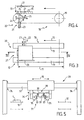
- Figure 3 describes, in top view, an example of implementation work of one of the steps of the process according to the invention.
- Figure 4 is a sectional view along line IV-IV shown in Figure 3.
- Figure 5 describes, in side view, another step of the process according to the invention.
- Figure 6 describes, in side view, an example of a suitable stencil to be used in the implementation of the method according to the invention.
- FIG. 7 describes, in axial view, an additional step, optional, of the process illustrated in figure 2.
- the present invention relates to a manufacturing process wall covering elements.
- a wall covering element 1 obtained by an example of implementation of the method according to the invention is notably illustrated. It is, for example, a slab capable of being placed on floor.
- the process according to the invention can also allow to obtain covering elements intended, in particular, for walls or ceilings.
- the slab 1 is formed, in particular, a support layer, in particular concrete 2, and a layer surface 3, made for example from cement and particles 4 of marble.
- Said treatment in particular for decorative purposes, makes it possible to make appear on said faces 5, for example, patterns of aesthetic appearance.
- said treatment is carried out using stencils 6 cooperating with said elements 1 during the latter.
- the expected acceleration then allows, thanks to time gained, to keep said elements 1 immobile and thus to provide a step automated precise placement of stencils 6.
- the stencil 6 provided for this purpose can then be positioned on item 1.
- Element 1 surmounted by stencil 6 thus fits into the area marked A to be processed.
- the progression rates gradually increase from zone B to zone A and from zone A to zone E.
- said elements 1 advance at a speed, in particular, constant and are spaced, for example, so substantially identical.
- the acceleration expected during the stages taking place in the zone marked C allows, according to the invention, to break this rhythm and, as mentioned above, to save time in order to be able to place the stencils 6 on elements 1 provided for in the judgment. In this way, the manufacture of said elements 1 can be conducted entirely continuously.
- the treatment provided for example at the level of the zone marked A is, in particular, a shot blasting.
- FIG. 2 it can be seen that, according to the illustrated mode for carrying out the invention, one routes, for example according to the arrows marked 14, the stencils 6 taken from the elements 1 after the treatment in order to position them on the elements 1 to be treated.
- said stencils 6 can be fed in flow, in particular continuous.
- the previous steps are identical, in zone D, when removing stencils 6. Indeed, these are taken from the locations where the elements 1 are positioned and then transferred so as to supply, in entry, the flow of stencils 6 directed, in particular, towards zone C, as mentioned upper.
- the present invention also relates to a device for implementation of the manufacturing process, presented above, of elements of coating of walls 1 in which a treatment is carried out, in particular for decorative, on at least one face 5 of said elements 1, using stencils 6 cooperating with said elements 1 during said treatment.
- the device according to the invention includes, for example, means 16 for ensuring an element flow 1, in particular in the zones marked A and / or B.
- This is, by example, at least a conveyor 17 on which the slabs are arranged.
- the device also comprises, by example, means 18 for accelerating at least one of said elements 1, in particular, at the level of zones C and / or D.
- these are consisting, for example, of at least two accelerator belt conveyors 19.
- said bands 19 are capable of transporting the elements 1, in particular, over a distance 11 given at a higher speed to that of the conveyors 17 which may be placed upstream for ensuring the flow.
- the device according to the invention also comprises, by example, means 20 for immobilizing and maintaining said element 1 of so as to position it, when stationary, in a precise location 12.
- Said means 20 for immobilizing and keeping immobile are thus constituted, in particular, of means 21 for ensuring a stop for the element in the direction of advancement and an axial positioning and means for ensuring transverse positioning 22.
- the means for ensuring a stop and an axial positioning 21 include, for example, a jack 23 and a spatula 24, suitable for being raised by said jack 23, in particular along the arrow marked 25.
- the jack 23 is actuated, for example, when a first cell 26, for example photoelectric, detects the arrival of an element 1.
- the spatula 23 is thus brought up and the progression of said element 1 is blocked.
- the advance of the accelerator bands 19 is however maintained, especially for a short time to ensure the correct positioning axial of said element 1.
- Means for ensuring transverse positioning 22 are constituted, in particular, by a second jack 27, provided orthogonal in the sense scroll 10, and a stop 28.
- the second cylinder 27 is actuated and thus makes it possible to block transversely element 1. Its axial positioning having been previously assured of precisely, said element 1 is thus positioned, when stationary, in a location of fixed coordinates.
- the device according to the invention also comprises, for example, means 29 for handling at least one of said stencils 6 with respect to said element 1, in particular provided at the level of zones C and / or D.
- the latter are consisting, for example, of a gantry 30 provided with gripping means 31 stencils 6, able to preposition them with respect to said elements 1.
- Said gripping means 31 have the function of transfer the stencils 6 between a conveyor belt 32 and the bands accelerators 19 provided in zones C and / or D.
- jaws 33 consist, for example, of jaws 33, able to be moved in particular using cylinders, vertically, according to the arrow marked 34 and / or horizontally according to the arrows identified 35.
- one of the two cylinders provided to allow the horizontal movement of the jaws 33 is lower mechanical resistance than the second. Thanks to that characteristic, when said jaws 33 maintain a stencil 6, the transverse position of the latter relative to the device is known from certainly, the lowest mechanical strength cylinder being at the end of race.
- the vertical uprights of the gantry 30 are provided, for example, stops 36, able, in particular to dampen the arrival of the means gripping 31 and ensuring the precise positioning of the latter by relation to the device.
- a stencil 6 is provided, at the end of its travel, on the conveyor belt 32. ensures its presence and the gripping means 31 of the gantry 30 come and collect it. It is then transferred, in the direction marked 15, to the accelerator bands 19 above which it is held at the end of race.
- the stencil 6 is positioned just above the location 12 where its presence is detected by a second cell 37, in particular photoelectric, identified in Figure 4. Said stencil 6 is then dropped on the element 1 after the latter has been blocked at said location 12.
- the steps described for handling of the stencils 6 are substantially identical to those indicated in the previous paragraphs, the order being simply reversed by compared to those described in the area marked C, so as to collect the stencils 6 present on the elements 1 after their treatment and place after transfer, on an evacuation conveyor belt.
- the device also comprises, optionally, means 38 for ensuring a effective and precise centering of the stencils 6 on the elements 1, in particular when their establishment.
- said means for centering include, in particular, springs 39, able to relax when the jaws 33 loosen. They thus allow the stencils 6 to be projected onto the elements 1.
- the means 38 for ensuring the centering further comprise, for example, lugs 40, provided on the front side of the stencils 6 so as to cooperate with the element 1 during the fall of said stencil 6.
- Said pins 40 have, along their edge interior, an oblique distal section 41 and a vertical proximal section 42. Said stencils 6 are thus introduced, perfectly centered, on the elements 1.
- the centering and horizontality of the positioning of the stencils 6 are also controlled, for example, by a cell 55, in particular photoelectric.
- the device according to the invention also comprises, by example, means for restoring the advance of the elements 1 according to the flow.
- accelerator bands 19 are driven, in particular by means known to those skilled in the art such as, in particular, electric motors capable of operating in jerks.
- the means 16 for ensuring the flow consist of at least one conveyor in continued. Said conveyors 17 thus allow a feeding of the belts accelerators 19 at a substantially constant flow.
- the device according to the invention comprises, so as to ensure the intended treatment, means 43 for blasting the elements 1, surmounted by stencils 6.
- Said means 43 according to a structure known to those skilled in the art, make it possible to bombard said elements 1 of fine particles, through days 48 of the stencil, suitable to modify the appearance of their face 5.
- the conveyor 17 ensuring the circulation of the elements 1 to level of said shot blasting means 43 consists, for example, of chains.
- the device also comprises, optionally, means 44 for rigging and / or polish said element 1.
- means 44 for rigging and / or polish said element 1. are provided, for example, in the zone marked B, in upstream of the accelerator strips 19 where the stencils 6 are placed on said elements 1. They consist, in particular, of grinding stones having a more or less fine grain.
- the device further comprises, optionally, means 45 for routing the stencils 6 taken from the elements 1 after their treatment in order to position them on the elements 1 to be treated.
- means 45 for routing the stencils 6 taken from the elements 1 after their treatment consist, in particular, of the conveyor belt 32, provided disposed between the gantry 30 D located in the zone D to ensure the removal of the stencils 6 after the treatment and the gantry 30 C being in the zone C for setting place said stencils 6 before treatment.
- bands 47 obtained on element 1 by an example of treatment such as shot blasting there are shown in Figure 1, bands 47 obtained on element 1 by an example of treatment such as shot blasting.
- the stencil 6 shown in Figure 6 allows, for example, thanks to days 48 of stencil of obtaining said strips 47.
- the device according to the invention comprises, according to a particular embodiment, means 49 for evacuate the residual beads remaining on said elements 1 after their exit means 43 for blasting. They are planned, particularly at the level of the zone marked E downstream of the accelerating strips 19 at the level of which the stencils 6 are taken from the elements 1.
- they consist, in particular, a conveyor belt 50, capable of tilting according to the arrow marked 51.
Landscapes
- Engineering & Computer Science (AREA)
- Mechanical Engineering (AREA)
- Structural Engineering (AREA)
- Chemical & Material Sciences (AREA)
- Ceramic Engineering (AREA)
- Application Of Or Painting With Fluid Materials (AREA)
- Devices For Post-Treatments, Processing, Supply, Discharge, And Other Processes (AREA)
Description
- on prévoit un flux desdits éléments, préalablement constitués, avançant à une première vitesse constante et régulièrement espacés entre eux,
- on accélère un par un lesdits éléments sur une distance donnée, en les transportant à une seconde vitesse supérieure à ladite première vitesse, et on immobilise et maintient lesdits éléments en les positionnant à l'arrêt en un emplacement donné,
- on positionne sur ledit élément arrêté et/ou on prélève dudit élément arrêté ledit pochoir au niveau dudit emplacement donné, préalablement au traitement et/ou respectivement postérieurement audit traitement, et
- on rétablit l'avance dudit élément selon le flux.
- des moyens pour assurer un flux desdits éléments, préalablement constitués, avançant à une première vitesse constante et régulièrement espacés entre eux,
- des moyens pour accélérer un par un lesdits éléments, sur une distance donnée, en le transportant à une seconde vitesse supérieure à ladite première vitesse
- des moyens pour immobiliser et maintenir ledit élément, en le positionnant à l'arrêt en un emplacement donné
- des moyens pour positionner sur ledit élément arrêté et/ou pour prélever dudit élément arrêté ledit pochoir au niveau dudit emplacement donné, préalablement au traitement et/ou postérieurement audit traitement, constituant lesdits moyens pour manipuler,
- des moyens pour rétablir l'avance dudit élément selon le flux.
- on accélère ledit élément 1 sur une distance donnée 11 et on le positionne à l'arrêt en un emplacement donné 12,
- on positionne sur ledit élément 1 et/ou on prélève dudit élément 1 ledit pochoir 6 au niveau dudit emplacement 12 donné, et ceci préalablement au traitement et/ou, respectivement, postérieurement audit traitement.
Claims (12)
- Procédé de fabrication d'éléments de revêtement de parois (1) dans lequel on réalise un traitement, notamment à but décoratif, sur au moins une face (5) desdits éléments (1), à l'aide de pochoirs (6) coopérant avec lesdits éléments (1), procédé dans lequel on manipule un desdits pochoirs (6) vis-à-vis d'un desdits éléments (1) pendant une étape de maintien dudit élément (1), caractérisé par le fait que :on prévoit un flux desdits éléments (1), préalablement constitués, avançant à une première vitesse constante et régulièrement espacés entre eux,on accélère un par un lesdits éléments (1) sur une distance donnée (11), en les transportant à une seconde vitesse supérieure à ladite première vitesse, et on immobilise et maintient lesdits éléments en les positionnant à l'arrêt en un emplacement donné (12),on positionne sur ledit élément (1) arrêté et/ou on prélève dudit élément (1) arrêté ledit pochoir (6) au niveau dudit emplacement (12) donné, préalablement au traitement et/ou respectivement postérieurement audit traitement, eton rétablit l'avance dudit élément (1) selon le flux.
- Procédé selon la revendication 1, dans lequel ledit traitement est un grenaillage et, préalablement audit traitement, on grèse et/ou on polit lesdits éléments (1).
- Procédé selon la revendication 1, dans lequel on achemine les pochoirs (6) prélevés sur les éléments (1) postérieurement à leur traitement afin de les positionner sur les éléments (1) devant être traités.
- Dispositif conçu pour la mise en oeuvre du procédé de fabrication d'éléments de revêtement de parois (1), selon la revendication 1, dans lequel on réalise un traitement, notamment à but décoratif, sur au moins une face (5) desdits éléments (1), à l'aide de pochoirs (6) coopérant avec lesdits éléments (1), dispositif comprenant des moyens (29) pour manipuler un desdits pochoirs (6) vis-à-vis d'un desdits éléments (1) pendant une étape de maintien dudit élément (1), caractérisé par le fait qu'il comprend en outre :des moyens (16) pour assurer un flux desdits éléments (1), préalablement constitués, avançant à une première vitesse constante et régulièrement espacés entre eux.des moyens (18) pour accélérer un par un un desdits éléments (1), sur une distance donnée, en le transportant à une seconde vitesse supérieure à ladite première vitessedes moyens (20) pour immobiliser et maintenir ledit élément (1), en le positionnant à l'arrêt en un emplacement donné (12)des moyens pour positionner sur ledit élément arrêté et/ou pour prélever dudit élément arrêté ledit pochoir au niveau dudit emplacement donné, préalablement au traitement et/ou postérieurement audit traitement, constituant lesdits moyens pour manipuler,des moyens pour rétablir l'avance dudit élément (1) selon le flux.
- Dispositif, selon la revendication 4, dans lequel les moyens (16) pour assurer le flux sont constitués par au moins un convoyeur en continu.
- Dispositif, selon la revendication 4, comprenant des moyens pour grenailler ledit élément (1) pour mener ledit traitement.
- Dispositif, selon la revendication 4, comprenant, en outre, des moyens pour gréser et/ou polir ledit élément (1).
- Dispositif, selon la revendication 4, comprenant en outre, des moyens pour acheminer les pochoirs (6) prélevés sur les éléments (1) postérieurement à leur traitement afin de les positionner sur les éléments (1) devant être traités.
- Dispositif, selon la revendication 4, dans lequel les moyens (18) pour accélérer sont constitués d'au moins deux convoyeurs à bandes (19), aptes à transporter les éléments (1) à une vitesse supérieure à celle des moyens (16) pour assurer le flux.
- Dispositif, selon la revendication 4, dans lequel les moyens (20) pour immobiliser et maintenir ledit élément (1) sont constitués par des moyens (21) pour assurer une butée pour ledit élément (1) dans le sens de l'avancement et un positionnement axial et par des moyens (22) pour assurer un positionnement transversal.
- Dispositif, selon la revendication 4, dans lequel les moyens (29) pour manipuler au moins un desdits pochoirs (6) sont constitués d'un portique (30) muni de moyens de préhension (31), comprenant des mâchoires (33), aptes à prépositionner lesdits pochoirs (6) par rapport auxdits éléments (1).
- Dispositif, selon la revendication 11, comprenant, en outre, des moyens (38) pour assurer un centrage précis des pochoirs (6) sur les éléments (1), constitués de ressorts (39) aptes à se détendre lorsque les mâchoires (33) se désserrent, et d'ergots (40), prévus sous la face antérieure des pochoirs (6).
Applications Claiming Priority (2)
| Application Number | Priority Date | Filing Date | Title |
|---|---|---|---|
| FR9512954A FR2740491B1 (fr) | 1995-10-27 | 1995-10-27 | Procede de fabrication d'elements de revetement de parois et dispositif concu pour sa mise en oeuvre |
| FR9512954 | 1995-10-27 |
Publications (2)
| Publication Number | Publication Date |
|---|---|
| EP0770456A1 EP0770456A1 (fr) | 1997-05-02 |
| EP0770456B1 true EP0770456B1 (fr) | 2002-08-28 |
Family
ID=9484169
Family Applications (1)
| Application Number | Title | Priority Date | Filing Date |
|---|---|---|---|
| EP19960490042 Expired - Lifetime EP0770456B1 (fr) | 1995-10-27 | 1996-10-25 | Procédé de fabrication d'éléments de revêtement de parois et dispositif conçu pour sa mise en oeuvre |
Country Status (3)
| Country | Link |
|---|---|
| EP (1) | EP0770456B1 (fr) |
| DE (1) | DE69623225T2 (fr) |
| FR (1) | FR2740491B1 (fr) |
Cited By (1)
| Publication number | Priority date | Publication date | Assignee | Title |
|---|---|---|---|---|
| CN103590562A (zh) * | 2013-11-22 | 2014-02-19 | 河南德晟环保节能科技有限公司 | 一种生产保温装饰一体化板的系统及工艺 |
Family Cites Families (6)
| Publication number | Priority date | Publication date | Assignee | Title |
|---|---|---|---|---|
| DE2252238A1 (de) * | 1972-10-25 | 1974-05-02 | Schindler & Co Kg | Verfahren und einrichtung zur herstellung von betonwerksteinplatten bzw. waschbetonplatten |
| JPS57127671A (en) * | 1981-01-23 | 1982-08-07 | Watanabe Tekkosho:Kk | Working device for stone surface pattern |
| JPH0659438B2 (ja) * | 1985-10-09 | 1994-08-10 | 株式会社日立製作所 | 塗装用ワーク移送方法及びそれを用いた装置 |
| DE3538292A1 (de) * | 1985-10-29 | 1987-04-30 | Nuetro Maschinenbau Gmbh | Vorrichtung zur handhabung von masken an einer lackierstrasse |
| DE9208681U1 (de) * | 1992-06-29 | 1993-02-25 | Schlick roto-jet Maschinenbau GmbH, 4439 Metelen | Schablonenvorrichtung zur Verwendung bei Strahlarbeiten zur Ornamentierung von Blöcken aus Gestein oder gesteinartigem Material |
| WO1995018020A2 (fr) * | 1993-12-24 | 1995-07-06 | Carlo Antonio Camorani | Procede serigraphique destine a la decoration d'articles, et appareil associe |
-
1995
- 1995-10-27 FR FR9512954A patent/FR2740491B1/fr not_active Expired - Fee Related
-
1996
- 1996-10-25 EP EP19960490042 patent/EP0770456B1/fr not_active Expired - Lifetime
- 1996-10-25 DE DE1996623225 patent/DE69623225T2/de not_active Expired - Fee Related
Cited By (2)
| Publication number | Priority date | Publication date | Assignee | Title |
|---|---|---|---|---|
| CN103590562A (zh) * | 2013-11-22 | 2014-02-19 | 河南德晟环保节能科技有限公司 | 一种生产保温装饰一体化板的系统及工艺 |
| CN103590562B (zh) * | 2013-11-22 | 2015-12-16 | 河南德晟环保节能科技有限公司 | 一种生产保温装饰一体化板的系统及工艺 |
Also Published As
| Publication number | Publication date |
|---|---|
| DE69623225T2 (de) | 2003-04-30 |
| EP0770456A1 (fr) | 1997-05-02 |
| FR2740491B1 (fr) | 1997-12-26 |
| FR2740491A1 (fr) | 1997-04-30 |
| DE69623225D1 (de) | 2002-10-02 |
Similar Documents
| Publication | Publication Date | Title |
|---|---|---|
| JP5524716B2 (ja) | ウェーハの平坦加工方法 | |
| EP1423244B9 (fr) | Dispositifs de decollement de substrats et procedes associes | |
| WO2018000053A1 (fr) | Coupe-dalles automatique | |
| CH694186A5 (fr) | Dispositif de r'ception et d''jection d''l'ments plats dans une machine les travaillant. | |
| FR2677626A1 (fr) | Dispositif de transfert d'objets plats, notamment pour machine de tri postal. | |
| FR2493814A1 (fr) | Dispositif de transport, notamment pour transporter et conserver en attente des objets en forme de barres, tels que des pieces a laminer | |
| EP0770456B1 (fr) | Procédé de fabrication d'éléments de revêtement de parois et dispositif conçu pour sa mise en oeuvre | |
| FR2964897A1 (fr) | Dispositif de rectification de la hauteur de blocs beton et l'installation de production de blocs beton equipee d'un tel dispositif | |
| TW201906060A (zh) | 剝離裝置 | |
| EP1252960B1 (fr) | Oxycoupage de brames froides ou chaudes sans cordons | |
| JP6845087B2 (ja) | 剥離装置 | |
| EP3939072B1 (fr) | Système de fracture d'une pluralité d'assemblages de tranches | |
| EP0205390A2 (fr) | Procédé et installation pour le chargement dans un conteneur et le déchargement de ce conteneur de pièces disposées en lits horizontaux | |
| FR2956342A1 (fr) | Machine automatisee de decoupe de quartiers de bois de chauffage en buches | |
| FR2476613A1 (fr) | Procede et dispositif de formation de couches de briques a l'etat de briquettes ou d'agglomeres | |
| EP1674413B1 (fr) | Procédé pour la gestion d'un flux de pièces et installation pour la mise en oeuvre de ce procédé | |
| EP3222367A1 (fr) | Procédé et installation de traitement de panneau ou plaque | |
| EP3322836B1 (fr) | Installation de traitement comprenant un dispositif de transfert entre une zone a pression atmosphérique et une zone sous vide, et procédé de mise en oeuvre correspondant | |
| FR2930175A1 (fr) | Outil de traitement d'une matiere de recuperation, installation et procede associes | |
| FR2533542A1 (fr) | Procedes et postes de preparation et de transfert d'unites de stockage, transport, et/ou manutention | |
| FR1465049A (fr) | Procédé et dispositif d'empilage de corps de forme, notamment de parpaings en béton, sous la forme de blocs de section carrée | |
| EP0244306A1 (fr) | Transfert de plaques de verre en vue de leur bombage | |
| FR2844212A1 (fr) | Procede et installation pour le tri morphologique automatique d'objets substantiellement spheriques. | |
| FR2775925A1 (fr) | Dispositif pour realiser le clivage de blocs de schistes ou ardoisiers de forme parallelepipedique | |
| FR2506733A1 (fr) | Dispositif pour le depot a plat, sur un vehicule, de tranches d'un produit initialement presentees sous la forme de pains tranches |
Legal Events
| Date | Code | Title | Description |
|---|---|---|---|
| PUAI | Public reference made under article 153(3) epc to a published international application that has entered the european phase |
Free format text: ORIGINAL CODE: 0009012 |
|
| AK | Designated contracting states |
Kind code of ref document: A1 Designated state(s): BE DE IT |
|
| 17P | Request for examination filed |
Effective date: 19971031 |
|
| 17Q | First examination report despatched |
Effective date: 19990622 |
|
| GRAG | Despatch of communication of intention to grant |
Free format text: ORIGINAL CODE: EPIDOS AGRA |
|
| GRAG | Despatch of communication of intention to grant |
Free format text: ORIGINAL CODE: EPIDOS AGRA |
|
| GRAH | Despatch of communication of intention to grant a patent |
Free format text: ORIGINAL CODE: EPIDOS IGRA |
|
| GRAH | Despatch of communication of intention to grant a patent |
Free format text: ORIGINAL CODE: EPIDOS IGRA |
|
| GRAA | (expected) grant |
Free format text: ORIGINAL CODE: 0009210 |
|
| AK | Designated contracting states |
Kind code of ref document: B1 Designated state(s): BE DE IT |
|
| REF | Corresponds to: |
Ref document number: 69623225 Country of ref document: DE Date of ref document: 20021002 |
|
| PLBE | No opposition filed within time limit |
Free format text: ORIGINAL CODE: 0009261 |
|
| STAA | Information on the status of an ep patent application or granted ep patent |
Free format text: STATUS: NO OPPOSITION FILED WITHIN TIME LIMIT |
|
| 26N | No opposition filed |
Effective date: 20030530 |
|
| PGFP | Annual fee paid to national office [announced via postgrant information from national office to epo] |
Ref country code: DE Payment date: 20031103 Year of fee payment: 8 |
|
| PGFP | Annual fee paid to national office [announced via postgrant information from national office to epo] |
Ref country code: BE Payment date: 20031211 Year of fee payment: 8 |
|
| PG25 | Lapsed in a contracting state [announced via postgrant information from national office to epo] |
Ref country code: BE Free format text: LAPSE BECAUSE OF NON-PAYMENT OF DUE FEES Effective date: 20041031 |
|
| BERE | Be: lapsed |
Owner name: S.A. *MAGRIS Effective date: 20041031 |
|
| PG25 | Lapsed in a contracting state [announced via postgrant information from national office to epo] |
Ref country code: DE Free format text: LAPSE BECAUSE OF NON-PAYMENT OF DUE FEES Effective date: 20050503 |
|
| PG25 | Lapsed in a contracting state [announced via postgrant information from national office to epo] |
Ref country code: IT Free format text: LAPSE BECAUSE OF NON-PAYMENT OF DUE FEES;WARNING: LAPSES OF ITALIAN PATENTS WITH EFFECTIVE DATE BEFORE 2007 MAY HAVE OCCURRED AT ANY TIME BEFORE 2007. THE CORRECT EFFECTIVE DATE MAY BE DIFFERENT FROM THE ONE RECORDED. Effective date: 20051025 |
|
| BERE | Be: lapsed |
Owner name: S.A. *MAGRIS Effective date: 20041031 |