EP0770512B1 - Kopfstütze für Kraftfahrzeugsitze - Google Patents
Kopfstütze für Kraftfahrzeugsitze Download PDFInfo
- Publication number
- EP0770512B1 EP0770512B1 EP95830448A EP95830448A EP0770512B1 EP 0770512 B1 EP0770512 B1 EP 0770512B1 EP 95830448 A EP95830448 A EP 95830448A EP 95830448 A EP95830448 A EP 95830448A EP 0770512 B1 EP0770512 B1 EP 0770512B1
- Authority
- EP
- European Patent Office
- Prior art keywords
- framework
- support rods
- resilient body
- headrest
- fitted
- Prior art date
- Legal status (The legal status is an assumption and is not a legal conclusion. Google has not performed a legal analysis and makes no representation as to the accuracy of the status listed.)
- Expired - Lifetime
Links
- 239000000463 material Substances 0.000 claims description 7
- 239000002184 metal Substances 0.000 claims description 5
- 239000002991 molded plastic Substances 0.000 claims description 4
- 239000004033 plastic Substances 0.000 claims description 3
- 229920003023 plastic Polymers 0.000 claims description 3
- 238000010276 construction Methods 0.000 description 4
- 230000006835 compression Effects 0.000 description 1
- 238000007906 compression Methods 0.000 description 1
- 238000006073 displacement reaction Methods 0.000 description 1
- 238000000465 moulding Methods 0.000 description 1
Images

Classifications
-
- B—PERFORMING OPERATIONS; TRANSPORTING
- B60—VEHICLES IN GENERAL
- B60N—SEATS SPECIALLY ADAPTED FOR VEHICLES; VEHICLE PASSENGER ACCOMMODATION NOT OTHERWISE PROVIDED FOR
- B60N2/00—Seats specially adapted for vehicles; Arrangement or mounting of seats in vehicles
- B60N2/80—Head-rests
- B60N2/806—Head-rests movable or adjustable
- B60N2/809—Head-rests movable or adjustable vertically slidable
- B60N2/812—Head-rests movable or adjustable vertically slidable characterised by their locking devices
- B60N2/818—Head-rests movable or adjustable vertically slidable characterised by their locking devices with stepwise positioning
Definitions
- the present invention relates to headrests for motor-vehicle seats, comprising a resilient body incorporating a framework of moulded plastics material having two spaced-apart hollow parts housing a pair of support rods, and in which adjustment means are provided for the stepwise height adjustment of the resilient body relative to the support rods.
- Headrests of the above-referenced type are known, for instance, from FR-A-2 577 869 and EP-A-0 322 373 in the name of the same Applicant.
- the invention is directed to a headrest of the type set forth in the above wherein, as in FR-A-2 577 869, said adjustment means include locking means carried by the framework for engaging positioning notches formed on the support rods.
- the said locking means comprise resilient members, whereby disengagement between the support rods and the resilient body of the headrest, so as to perform in use the vertical adjustment thereof, is simply carried out by pushing or pulling the resilient body along the axial direction of the support rods.
- This construction may involve risks of undesired withdrawal of the resilient body relative to the support rods, for instance in case of collisions of the vehicle on which the headrest is installed, with dangerous consequences for the passengers.
- the object of the present invention is to provide a headrest for motor-vehicle seats overcoming the above drawback, with a light and relatively simple and economical construction.
- this object is achieved by virtue of the fact that, in a headrest for motor-vehicle seats of the type set forth at the beginning, the support rods are axially slidably fitted within respective tubular members housed inside said hollow parts of the framework and relative to which the resilient body can swing between angular engagement and respectively disengagement positions between said locking means and said positioning notches; each of said tubular members having an upper end provided with a pair of lateral opposed apertures receiving rocking pin arms of a respective transverse fork element fitted in a corresponding seat of the respective hollow part of the framework, and a lower end having a front opening and a rear projection to which a respective thrust spring is associated, tending to maintain said resilient body in said engagement angular position, and of the fact that said locking means comprise a pair of metal straps fitted within said framework so as to engage the positioning notches of said support rods, in the engagement angular position of said resilient body, through the front openings of said tubular members.
- Each thrust spring is conveniently wound over the rear projection of the respective tubular member and directly bears against the wall of the corresponding hollow part of the framework.
- each of said transverse fork elements may to advantage be resilient and snap fitted into the corresponding seat of the respective hollow part of the framework.
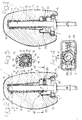
- reference numeral 1 generally designates a headrest intended to be installed on top of the backrest of a motor-vehicle seat (not shown).
- the headrest 1 comprises a resilient body or pillow 2, normally made of foamed plastics material having an outer covering 3, and a load-bearing framework 4 incorporated within the resilient body 2.
- the framework 4 is formed in one piece of moulded plastics material and comprises two spaced-apart hollow parts 5 having a substantially quadrangular cross section progressively widening towards the base of the framework 4, indicated as 6, in correspondence of which a cover 7 is secured.
- Each support rod 8 is formed by a cylindrical metal core 9 (figures 4 and 5) over which a thick covering 10 of plastics material is applied by moulding.
- a vertical row of notches 11 is formed, which are intended, as clarified herebelow, for height adjustment of the resilient body 2 relative to the support rods 8.
- each support rod 8 On its rear side, the covering 10 of each support rod 8 is formed with an upper key appendage 17.
- each support rod 8 and the respective hollow part 5 of the framework 4 a corresponding tubular member 12 is interposed, also made of moulded plastics material.
- Each tubular member 12 is housed with angular clearance within the respective hollow part 5, and each support rod 8 is axially slidably fitted within the respective tubular member 12.
- each tubular member 12 is connected superiorly to the corresponding upper area of the respective hollow part 5 in a swingable way, by means of a transverse fork element 13 housed in a corresponding seat 14 of the tubular part 5 and having a pair of rocking pin arms 15 received into corresponding lateral apertures 16 of the tubular member 12.
- the fork element 13 is resilient and mounting thereof into the seat 14, together with engagement of the pin arms 15 into the aperture 16, is performed by snap fitting.
- This construction enables the resilient body 2 to swing relative to the support rods 8, such as better clarified in the following, between an angular engagement position depicted in figure 2, and an angular disengagement position shown in figure 3.
- Each tubular element 12 is innerly formed with a centering axial groove 18 along which the key appendage 17 of the respective support rod 8 is slidably fitted. Moreover, near to its lower end, each tubular member 12 is provided with a front opening 19, aligned with the notches 11 of the respective support rod 8, and with an integral rear projection 20 over which a helical spring 21 is wound, directly reacting against the rear wall of the respective hollow part 5.
- each tubular member 12 cooperates with a locking tooth 22 formed by the end of a respective metal bent strap 23 secured in the corresponding front area of the hollow part 5.
- the resilient body 1 Upon reaching the desired height positioning, the resilient body 1 is released and thus pushed by the action of the thrust springs 21 to the initial engagement position, shown in figure 2.
Landscapes
- Engineering & Computer Science (AREA)
- Aviation & Aerospace Engineering (AREA)
- Transportation (AREA)
- Mechanical Engineering (AREA)
- Chair Legs, Seat Parts, And Backrests (AREA)
- Seats For Vehicles (AREA)
Claims (4)
- Kopfstütze (1) für Kraftfahrzeug-Sitze, aufweisend einen elastischen Körper (2), der ein geformtes Kunststoffmaterial-Tragwerk (4) enthält, das zwei beabstandete Hohlteile (5) hat, die ein Paar von Haltestäben (8) aufnehmen, und wobei Einstelleinrichtungen (11, 22) vorgesehen sind für die stufenweise Höhenverstellung des elastischen Körpers (2) relativ zu den Haltestäben (8), wobei die Einstelleinrichtungen Verriegelungseinrichtungen (22) aufweisen, die durch das Tragwerk (4) getragen werden, um Positionierkerben (11), die an den Haltestäben (8) gebildet, in Eingriff zu stellen, dadurch gekennzeichnet, daß die Haltestäbe (8) axial gleitfähig eingepaßt sind in jeweiligen rohrförmigen Elementen (12), die innerhalb der Hohlteile (5) des Tragwerks (4) aufgenommen sind und relativ zu welchen der elastische Körper (2) zwischen jeweiligen winkelmäßigen Eingriffs- und Lösungspositionen zwischen der Verriegelungseinrichtung (22) und den Positionierkerben (11) schwingen bzw. schwenken kann; wobei jedes der rohrförmigen Elemente (12) ein oberes Ende hat, das mit einem Paar von gegenüberliegenden seitlichen Öffnungen (16) versehen ist, die schwingende bzw. hin- und herbewegende Zapfenarme (15) eines jeweiligen Quergabelelementes (13) aufnehmen, eingepaßt in einen entsprechenden Sitz (14) des jeweiligen Hohlteils (5) des Tragwerks (4), und ein unteres Ende, das eine Vorderöffnung (19) und einen Rückvorsprung (20) hat, mit dem eine jeweilige Schubfeder (21) verbunden ist, die dazu neigt, den elastischen Körper (2) in der winkelmäßigen Eingriffsposition zu halten, und dadurch, daß die Verriegelungseinrichtung ein Paar von Metallbändern (23) aufweist, eingepaßt in dem Tragwerk (4), um die Positionierkerben (11) der Haltestäbe (8) einzugreifen, und zwar in der winkelmäßigen Eingriffsposition des elastischen Körpers (2), und zwar durch die Vorderöffnungen (19) der rohrförmigen Elemente (12).
- Kopfstütze gemäß Anspruch 1, dadurch gekennzeichnet, daß jede Schubfeder (21) gewickelt ist über den Rückvorsprung (20) des jeweiligen rohrförmigen Elementes (12) und direkt gegen die Wand des entsprechenden Hohlteils (12) des Tragwerks (4) anliegt.
- Kopfstütze gemäß Anspruch 1 und Anspruch 2, dadurch gekennzeichnet, daß jedes Quergabelelement (13) elastisch ist und eingerastet ist in dem entsprechenden Sitz (14) des jeweiligen Hohlteils (5) des Tragwerks (4).
- Kopfstütze gemäß einem der vorhergehenden Ansprüche, dadurch gekennzeichnet, daß jeder Haltestab (8) mit einer Kunststoffmaterial-Deckschicht (10) versehen ist, die geformt ist über einem Metallkern (9), auf der vorderen Seite dessen die Positionierkerben (11) gebildet sind und auf der Hinterseite dessen ein Bezugsschlüssel-Vorsprung (17) gebildet ist, und zwar gleitfähig im Eingriff längs einer entsprechenden inneren hinteren Rille (18) des jeweiligen rohrförmigen Elementes (12).
Priority Applications (3)
| Application Number | Priority Date | Filing Date | Title |
|---|---|---|---|
| EP95830448A EP0770512B1 (de) | 1995-10-23 | 1995-10-23 | Kopfstütze für Kraftfahrzeugsitze |
| DE69503787T DE69503787T2 (de) | 1995-10-23 | 1995-10-23 | Kopfstütze für Kraftfahrzeugsitze |
| ES95830448T ES2120156T3 (es) | 1995-10-23 | 1995-10-23 | Reposacabezas para asiento de vehiculo automovil. |
Applications Claiming Priority (1)
| Application Number | Priority Date | Filing Date | Title |
|---|---|---|---|
| EP95830448A EP0770512B1 (de) | 1995-10-23 | 1995-10-23 | Kopfstütze für Kraftfahrzeugsitze |
Publications (2)
| Publication Number | Publication Date |
|---|---|
| EP0770512A1 EP0770512A1 (de) | 1997-05-02 |
| EP0770512B1 true EP0770512B1 (de) | 1998-07-29 |
Family
ID=8222037
Family Applications (1)
| Application Number | Title | Priority Date | Filing Date |
|---|---|---|---|
| EP95830448A Expired - Lifetime EP0770512B1 (de) | 1995-10-23 | 1995-10-23 | Kopfstütze für Kraftfahrzeugsitze |
Country Status (3)
| Country | Link |
|---|---|
| EP (1) | EP0770512B1 (de) |
| DE (1) | DE69503787T2 (de) |
| ES (1) | ES2120156T3 (de) |
Families Citing this family (9)
| Publication number | Priority date | Publication date | Assignee | Title |
|---|---|---|---|---|
| DE19707477A1 (de) * | 1997-02-25 | 1998-08-27 | Bayerische Motoren Werke Ag | Rücksitzbank in einem Kraftfahrzeug |
| DE29811875U1 (de) * | 1998-07-03 | 1999-11-11 | Johnson Controls GmbH, 51399 Burscheid | Verriegelungsvorrichtung und höhenverstellbar verriegelbare Kopfstütze |
| EP0970846A1 (de) * | 1998-07-09 | 2000-01-12 | Gestind M.B. Manifattura Di Bruzolo S.P.A | Kopfstütze für Kraftfahrzeug |
| PL194396B1 (pl) * | 1999-07-16 | 2007-05-31 | Gestind Poland Sp Z Oo | Zagłówek fotela samochodowego |
| FR2888175A1 (fr) * | 2005-07-08 | 2007-01-12 | Cera | Procede de realisation d'un appui-tete comprenant un dispositif de reglage a l'interieur du coussin en mousse |
| WO2011107852A1 (en) * | 2010-03-01 | 2011-09-09 | Kongsberg Automotive Ab | Adjustment mechanism for a vehicle seat headrest |
| CN104550473B (zh) * | 2014-12-31 | 2017-11-28 | 无锡曙光模具有限公司 | 轿车座椅头枕管的齿形成型模具 |
| JP6513967B2 (ja) * | 2015-02-26 | 2019-05-15 | 日本発條株式会社 | ヘッドレスト装置 |
| CN113212272B (zh) * | 2021-06-21 | 2022-11-18 | 诺创汽车科技(上海)有限公司 | 车辆 |
Family Cites Families (7)
| Publication number | Priority date | Publication date | Assignee | Title |
|---|---|---|---|---|
| FR1561172A (de) * | 1967-12-12 | 1969-03-28 | ||
| JPS57144135A (en) * | 1981-02-26 | 1982-09-06 | Mazda Motor Corp | Up and down controller for head rest of automobile |
| IT8553031U1 (it) | 1985-02-26 | 1986-08-26 | Gestind Mb Manifattura Di Bruzolo S P A | Appoggiatesta con ossatura in due semi-gusci per autovetture |
| ES2022712B3 (es) | 1987-12-21 | 1991-12-01 | Gestind-M B Manifattura Di Bruzolo S P A | Reposacabezas para asientos de vehiculos de motor. |
| DE4222921C2 (de) * | 1992-07-11 | 1996-02-01 | Daimler Benz Ag | Höhenverschiebbare Kopfstütze für einen Kraftwagensitz |
| EP0582765B1 (de) * | 1992-08-11 | 1995-11-15 | Gestind M.B. Manifattura Di Bruzolo S.P.A | Kopfstütze für Kraftfahrzeugsitze |
| IT1256975B (it) * | 1992-10-21 | 1995-12-27 | Bruzolo Manifatt Gestind Mb | Ossatura interna del poggiatesta veicolare. |
-
1995
- 1995-10-23 EP EP95830448A patent/EP0770512B1/de not_active Expired - Lifetime
- 1995-10-23 ES ES95830448T patent/ES2120156T3/es not_active Expired - Lifetime
- 1995-10-23 DE DE69503787T patent/DE69503787T2/de not_active Expired - Fee Related
Also Published As
| Publication number | Publication date |
|---|---|
| DE69503787D1 (de) | 1998-09-03 |
| ES2120156T3 (es) | 1998-10-16 |
| DE69503787T2 (de) | 1998-12-10 |
| EP0770512A1 (de) | 1997-05-02 |
Similar Documents
| Publication | Publication Date | Title |
|---|---|---|
| US6068337A (en) | Headrest for motor-vehicle seats | |
| EP1206367B1 (de) | Klappbare u-förmige kopfstütze | |
| US6056364A (en) | Headrest for motor-vehicle seats | |
| CA2148869C (en) | Modular automotive seat frame | |
| US5895094A (en) | Headrest apparatus for vehicle seat | |
| US5409297A (en) | Arm rest for motor vehicle rear seats | |
| US5743596A (en) | Safety fixture for removable seat of the vehicle | |
| EP2901894B1 (de) | Kopfstütze | |
| US4621864A (en) | Tiltable arm rest assembly and mounting and operating means therefor | |
| EP0770512B1 (de) | Kopfstütze für Kraftfahrzeugsitze | |
| EP1415851B1 (de) | Fahrzeugsitz | |
| EP0594543B1 (de) | Kopfstütze für Kraftfahrzeugsitze, insbesondere Fondsitze | |
| AU7991601A (en) | Child safety device adaptable on a vehicle | |
| EP0694436B1 (de) | Vorrichtung zum Schnellverbinden eines Kindersitzes mit einem Kraftwagensitz | |
| EP0819568B1 (de) | Kopfstütze für Kraftfahrzeugsitze | |
| EP0743222B1 (de) | Vorrichtung zur Höhenverstellung für einen Stützstab einer Kopfstütze für Fahrzeugsitze | |
| EP0743223B1 (de) | Struktur für Fahrzeugsitzkopfstütze | |
| EP0864461B1 (de) | Kopfstütze für Kraftfahrzeugsitze mit schneller Höhenverstellung | |
| EP0819571B1 (de) | Kopfstütze für Kraftfahrzeugsitze | |
| KR101683428B1 (ko) | 시트의 헤드레스트 가이드 조립체 | |
| KR20190035292A (ko) | 헤드레스트 조절장치 | |
| CA2366422A1 (en) | Bracket for mounting either a fixed or a pivoting armrest | |
| US5713636A (en) | Headrest for motor vehicle seats | |
| JPS6342852Y2 (de) | ||
| JPH0430930Y2 (de) |
Legal Events
| Date | Code | Title | Description |
|---|---|---|---|
| PUAI | Public reference made under article 153(3) epc to a published international application that has entered the european phase |
Free format text: ORIGINAL CODE: 0009012 |
|
| AK | Designated contracting states |
Kind code of ref document: A1 Designated state(s): DE ES FR GB IT SE |
|
| 17P | Request for examination filed |
Effective date: 19970805 |
|
| GRAG | Despatch of communication of intention to grant |
Free format text: ORIGINAL CODE: EPIDOS AGRA |
|
| GRAG | Despatch of communication of intention to grant |
Free format text: ORIGINAL CODE: EPIDOS AGRA |
|
| GRAH | Despatch of communication of intention to grant a patent |
Free format text: ORIGINAL CODE: EPIDOS IGRA |
|
| 17Q | First examination report despatched |
Effective date: 19980119 |
|
| GRAH | Despatch of communication of intention to grant a patent |
Free format text: ORIGINAL CODE: EPIDOS IGRA |
|
| GRAA | (expected) grant |
Free format text: ORIGINAL CODE: 0009210 |
|
| AK | Designated contracting states |
Kind code of ref document: B1 Designated state(s): DE ES FR GB IT SE |
|
| REF | Corresponds to: |
Ref document number: 69503787 Country of ref document: DE Date of ref document: 19980903 |
|
| REG | Reference to a national code |
Ref country code: ES Ref legal event code: FG2A Ref document number: 2120156 Country of ref document: ES Kind code of ref document: T3 |
|
| ET | Fr: translation filed | ||
| PLBE | No opposition filed within time limit |
Free format text: ORIGINAL CODE: 0009261 |
|
| STAA | Information on the status of an ep patent application or granted ep patent |
Free format text: STATUS: NO OPPOSITION FILED WITHIN TIME LIMIT |
|
| 26N | No opposition filed | ||
| PGFP | Annual fee paid to national office [announced via postgrant information from national office to epo] |
Ref country code: ES Payment date: 20011030 Year of fee payment: 7 |
|
| PGFP | Annual fee paid to national office [announced via postgrant information from national office to epo] |
Ref country code: SE Payment date: 20011031 Year of fee payment: 7 Ref country code: GB Payment date: 20011031 Year of fee payment: 7 Ref country code: FR Payment date: 20011031 Year of fee payment: 7 |
|
| PGFP | Annual fee paid to national office [announced via postgrant information from national office to epo] |
Ref country code: DE Payment date: 20011231 Year of fee payment: 7 |
|
| REG | Reference to a national code |
Ref country code: GB Ref legal event code: IF02 |
|
| PG25 | Lapsed in a contracting state [announced via postgrant information from national office to epo] |
Ref country code: GB Free format text: LAPSE BECAUSE OF NON-PAYMENT OF DUE FEES Effective date: 20021023 |
|
| PG25 | Lapsed in a contracting state [announced via postgrant information from national office to epo] |
Ref country code: SE Free format text: LAPSE BECAUSE OF NON-PAYMENT OF DUE FEES Effective date: 20021024 Ref country code: ES Free format text: LAPSE BECAUSE OF NON-PAYMENT OF DUE FEES Effective date: 20021024 |
|
| PG25 | Lapsed in a contracting state [announced via postgrant information from national office to epo] |
Ref country code: DE Free format text: LAPSE BECAUSE OF NON-PAYMENT OF DUE FEES Effective date: 20030501 |
|
| EUG | Se: european patent has lapsed | ||
| GBPC | Gb: european patent ceased through non-payment of renewal fee |
Effective date: 20021023 |
|
| PG25 | Lapsed in a contracting state [announced via postgrant information from national office to epo] |
Ref country code: FR Free format text: LAPSE BECAUSE OF NON-PAYMENT OF DUE FEES Effective date: 20030630 |
|
| REG | Reference to a national code |
Ref country code: FR Ref legal event code: ST |
|
| REG | Reference to a national code |
Ref country code: ES Ref legal event code: FD2A Effective date: 20031112 |
|
| PG25 | Lapsed in a contracting state [announced via postgrant information from national office to epo] |
Ref country code: IT Free format text: LAPSE BECAUSE OF NON-PAYMENT OF DUE FEES;WARNING: LAPSES OF ITALIAN PATENTS WITH EFFECTIVE DATE BEFORE 2007 MAY HAVE OCCURRED AT ANY TIME BEFORE 2007. THE CORRECT EFFECTIVE DATE MAY BE DIFFERENT FROM THE ONE RECORDED. Effective date: 20051023 |