EP0770540A2 - Véhicule automobile avec sièges à dossiers rabattables - Google Patents
Véhicule automobile avec sièges à dossiers rabattables Download PDFInfo
- Publication number
- EP0770540A2 EP0770540A2 EP96115262A EP96115262A EP0770540A2 EP 0770540 A2 EP0770540 A2 EP 0770540A2 EP 96115262 A EP96115262 A EP 96115262A EP 96115262 A EP96115262 A EP 96115262A EP 0770540 A2 EP0770540 A2 EP 0770540A2
- Authority
- EP
- European Patent Office
- Prior art keywords
- motor vehicle
- areas
- cross member
- vehicle according
- fastening devices
- Prior art date
- Legal status (The legal status is an assumption and is not a legal conclusion. Google has not performed a legal analysis and makes no representation as to the accuracy of the status listed.)
- Granted
Links
- 238000004804 winding Methods 0.000 claims description 6
- 230000008878 coupling Effects 0.000 description 2
- 238000010168 coupling process Methods 0.000 description 2
- 238000005859 coupling reaction Methods 0.000 description 2
- 230000009286 beneficial effect Effects 0.000 description 1
- 230000002349 favourable effect Effects 0.000 description 1
- 238000009434 installation Methods 0.000 description 1
- 230000010355 oscillation Effects 0.000 description 1
- 230000004043 responsiveness Effects 0.000 description 1
- 230000000452 restraining effect Effects 0.000 description 1
Images
Classifications
-
- B—PERFORMING OPERATIONS; TRANSPORTING
- B60—VEHICLES IN GENERAL
- B60N—SEATS SPECIALLY ADAPTED FOR VEHICLES; VEHICLE PASSENGER ACCOMMODATION NOT OTHERWISE PROVIDED FOR
- B60N2/00—Seats specially adapted for vehicles; Arrangement or mounting of seats in vehicles
- B60N2/24—Seats specially adapted for vehicles; Arrangement or mounting of seats in vehicles for particular purposes or particular vehicles
- B60N2/32—Seats specially adapted for vehicles; Arrangement or mounting of seats in vehicles for particular purposes or particular vehicles convertible for other use
- B60N2/36—Seats specially adapted for vehicles; Arrangement or mounting of seats in vehicles for particular purposes or particular vehicles convertible for other use into a loading platform
- B60N2/366—Seats specially adapted for vehicles; Arrangement or mounting of seats in vehicles for particular purposes or particular vehicles convertible for other use into a loading platform characterised by the locking device
-
- B—PERFORMING OPERATIONS; TRANSPORTING
- B62—LAND VEHICLES FOR TRAVELLING OTHERWISE THAN ON RAILS
- B62D—MOTOR VEHICLES; TRAILERS
- B62D25/00—Superstructure or monocoque structure sub-units; Parts or details thereof not otherwise provided for
Definitions
- the invention relates to a motor vehicle with foldable seat backs on rear seats and with a cross member releasably connectable to the seat backs in the upper region thereof, the front end regions of which can be releasably attached to fastening devices arranged in opposite directions on the inner body.
- Seat belts for people sitting on the rear seats of a motor vehicle can be attached to the inner body of the motor vehicle for the persons sitting outside in each case.
- the rear seats are designed to accommodate, for example, three people and the seat belt for the middle person is attached to the seat back provided for this purpose, it is necessary for safety reasons to support the corresponding seat back against the inner body of the motor vehicle in such a way that the restraining forces of the seat belt from the inside walls of the body.
- a cross member of the type mentioned is known, which is detachably attachable on the one hand in the upper region of the rear sides of the rear seat backrests and on the other hand detachably attachable by means of fastening devices to oppositely arranged areas of the inner body. If the area of the rear seats is to be used as a loading space, the cross member can be used both by the seat backs and by the ones at the front ends Fasteners are loosened and removed. The backrests can then be folded down so that the space can be used as a loading space.
- the fastening devices are designed such that the cross member is locked relative to the inner body of the motor vehicle in the direction of travel of the motor vehicle, that is to say transversely to the longitudinal direction of the cross member.
- the invention has for its object to remodel motor vehicles of the type mentioned so that the function of the cross member is expanded or improved.
- the front end areas of the cross member are non-positively connected to the opposite areas of the inner body in the attached position via the fastening devices. This ensures that the cross member is not only connected to the opposite areas of the inner body at its front end areas that forces can be transmitted transversely to the longitudinal direction of the cross member, but also that a non-positive connection of the opposite areas of the inner body of the motor vehicle via the cross member he follows. This leads to a more favorable vibration and noise behavior of the motor vehicle body.
- the body represents a relatively large interior space that is open to the rear and is formed between the area of the backrests of the front seats and the rear door of the motor vehicle by the floor assembly, the roof and the side walls with an inadequate cross-connection .
- the cross member is used in addition to its original function to stabilize the interior of the motor vehicle and thus to increase the body rigidity and the Reduce body responsiveness to vibrations. This beneficial effect occurs when the cross member is in the installation position, that is, when the motor vehicle is primarily used to transport people and not bulky loads.
- the fastening devices can be designed as clamping devices with conically shaped receiving areas for the front end areas of the cross member.
- the end regions of the crossmember have correspondingly conical bearing regions.
- the receiving areas and the contact areas are designed as conical receiving surfaces.
- one of the receiving surfaces of the fastening devices is inclined obliquely against the direction of travel when viewed from the bottom up.
- the clamping devices can be designed, for example, as toggle lever locking devices. Alternatively, it can be provided that the clamping devices have clamping levers and pawls.
- the cross member is formed at least in its section lying between the end areas as a continuous longitudinal slit having a hollow profile body.
- a foldable rear parcel shelf can be locked in the longitudinal slot will.
- the hollow profile body can be designed to receive a winding shaft for a luggage compartment blind, the free end of which is guided outwards through the longitudinal slot of the hollow profile body.
- the end regions of the cross member are designed as end pieces which are arranged at the ends of the hollow profile body and which have conical mutually abutting surfaces and bearing arrangements for the winding shaft.
- the attachment devices can be attached to brackets, which are each arranged between the rear wheel house and the C-pillar structure of the motor vehicle.
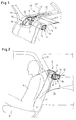
- a motor vehicle designed as a so-called combi vehicle has a split, foldable seat back 1 on the rear seats 2.
- a seat belt 3 for a middle person 4 sitting between two outside people has a retractor 5 which is attached in the upper region of the seat back 1.
- a cross member 6 is used, which is detachably connected on the one hand to the seat back and on the other hand with its front end areas to the inner body.
- backrest locks 7 are attached to the cross member, in the opening of which one of the locking elements 8 fixed to the seat back can engage. The lock can be released by actuating an unlocking lever 9.
- a number of backrest locks are provided over the length of the cross member 6.
- the cross member 6 is designed as a hollow profile body, which receives in its cavity 10 a winding shaft 11 for a luggage compartment blind 12, which is led out of a longitudinal slot 13 in the direction of the arrow to the outside.
- the winding shaft 10 is mounted in end pieces 14 of the cross member 6.
- the end pieces are arranged at the ends of the hollow profile body and firmly connected to it.
- the end pieces 14 can be non-positively connected to opposite areas 15 of the inner body of the motor vehicle.
- 18 fastening devices are each provided on a bracket for the non-positive connection of the end regions of the cross member 6.
- the fastening device is as Clamping device in the form of a toggle lever lock 19, the locking position of the toggle lever lock being shown in extended and the open position in dash-dotted lines in FIGS. 1 and 3.
- the toggle lock 19 is rigidly connected to the inner body of the vehicle via the bracket 18.
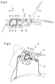
- the profile of the end piece 14 of the cross member 6 can be seen in FIG. 3.
- the bearing arrangement for the winding shaft of the luggage compartment blind is shown schematically at 20.
- the toggle lock 19 has approximately V-shaped, tapered receiving areas 21 and 22 for correspondingly tapered bearing areas 23, 24 of the end piece 14.
- the receiving areas 21 and 22 and the contact areas 23 and 24 are each designed as receiving surfaces or contact surfaces.
- the toggle lever lock 19 has a clamping lever 25 which is connected to a hand lever 27 via an elastic coupling 26. Due to the toggle action in the dead area of the articulated chain formed in this way, a high contact pressure of the clamping lever 25 against an area 28 of the end piece 14 of the cross member 6 is achieved, so that in this way a positive connection between the cross member 6 and the opposite areas of the inner body is achieved. Tolerance compensation within the lever system can take place either via the elastic coupling 26 or via an eccentric bolt at the pivot point 30.
- the elements of the toggle lock in the open position are each marked with "'".
- the seat backs 1 Due to the non-positive connection of the cross member, the seat backs 1 are supported in a known manner in the direction of travel A of the motor vehicle with respect to the inner body, and on the other hand a rigid transverse bond is achieved within the body structure, thereby preventing or reducing vibrations and roaring noises.
- FIG. 4 shows a further embodiment of the fastening device designed as a clamping device, the profile of the end piece denoted here by 14 ′ being designed differently on an end region of the cross member 6 compared to the illustration in FIGS. 1 and 3.
- a pivotally mounted clamping lever 32 is provided on a console attached to the inner body and generally designated 31, which can be locked in the clamping position by means of a schematically illustrated pawl 33.
- the release can take place via a device designated as a whole with 34.
- an elastic pressure piece 35 is provided which bears against an outer region 36 of the end piece 14 '.
- the end piece 14 ' with conical bearing areas 23' and 24 'bears against correspondingly conical receiving areas 21' and 22 '.
- a further receiving area 38 with an associated contact area 39 is provided in between.
Landscapes
- Engineering & Computer Science (AREA)
- Transportation (AREA)
- Mechanical Engineering (AREA)
- Aviation & Aerospace Engineering (AREA)
- Chemical & Material Sciences (AREA)
- Combustion & Propulsion (AREA)
- Body Structure For Vehicles (AREA)
- Seats For Vehicles (AREA)
- Vehicle Step Arrangements And Article Storage (AREA)
Applications Claiming Priority (2)
| Application Number | Priority Date | Filing Date | Title |
|---|---|---|---|
| DE19540048 | 1995-10-27 | ||
| DE19540048A DE19540048C2 (de) | 1995-10-27 | 1995-10-27 | Kraftfahrzeug |
Publications (3)
| Publication Number | Publication Date |
|---|---|
| EP0770540A2 true EP0770540A2 (fr) | 1997-05-02 |
| EP0770540A3 EP0770540A3 (fr) | 1998-03-18 |
| EP0770540B1 EP0770540B1 (fr) | 2001-12-12 |
Family
ID=7775947
Family Applications (1)
| Application Number | Title | Priority Date | Filing Date |
|---|---|---|---|
| EP96115262A Expired - Lifetime EP0770540B1 (fr) | 1995-10-27 | 1996-09-24 | Véhicule automobile avec sièges à dossiers rabattables |
Country Status (3)
| Country | Link |
|---|---|
| US (1) | US5758919A (fr) |
| EP (1) | EP0770540B1 (fr) |
| DE (2) | DE19540048C2 (fr) |
Cited By (1)
| Publication number | Priority date | Publication date | Assignee | Title |
|---|---|---|---|---|
| EP0928734A4 (fr) * | 1996-09-24 | 2001-12-05 | Toyota Motor Co Ltd | Construction renforcee pour passage de roue arriere d'une automobile et dispositif de fixation utilise dans cette construction |
Families Citing this family (8)
| Publication number | Priority date | Publication date | Assignee | Title |
|---|---|---|---|---|
| DE19832630C1 (de) * | 1998-07-21 | 2000-02-24 | Daimler Chrysler Ag | Gurtanordnung in einem Kraftfahrzeug |
| US6592149B2 (en) * | 2000-11-28 | 2003-07-15 | Paris E. Sessoms | Positioning devices for vehicle occupant restraints |
| US6786551B2 (en) | 2001-10-08 | 2004-09-07 | Lear Corporation | Seat latching assembly |
| US20030201592A1 (en) * | 2002-04-26 | 2003-10-30 | Rich Cummines | Apparatus and method for a compression spindle assembly for clamping |
| DE10234283B4 (de) * | 2002-07-26 | 2005-06-09 | Bos Gmbh & Co. Kg | Kfz-Sicherheitseinrichtung, wie Laderaumabdeckung, Trennnetz, Sonnenrollo od. dgl. |
| DE10235885B3 (de) * | 2002-08-06 | 2004-04-15 | Faurecia Autositze Gmbh & Co. Kg | Fahrzeugsitz |
| DE102005041744A1 (de) * | 2005-09-02 | 2007-03-08 | Bayerische Motoren Werke Ag | Sicherungseinrichtung an einer Entriegelungseinrichtung, insbesondere an der Rückenlehne eines Kraftfahrzeugs |
| GB2522417B (en) | 2014-01-22 | 2016-09-14 | Ford Global Tech Llc | Roll cover assembly |
Family Cites Families (13)
| Publication number | Priority date | Publication date | Assignee | Title |
|---|---|---|---|---|
| US2968190A (en) * | 1958-02-17 | 1961-01-17 | Borg Warner | Transmission mechanism |
| DE1650681B2 (de) * | 1967-09-19 | 1972-12-21 | Eisenwerk Wulfel, 3000 Hannover Wulfel | Schmiervorrichtung fuer die lagerstellen der planetenraeder bei planetengetrieben mit umlaufendem planetenradtraeger |
| JPS49125434U (fr) * | 1973-02-27 | 1974-10-26 | ||
| GB1498946A (en) * | 1974-08-24 | 1978-01-25 | Courtis N | Assembly for providing anchorage points in motor vehicles for attachment of passenger restraint devices |
| DE2729877A1 (de) * | 1977-07-01 | 1979-01-11 | Eberhardt Kraftfahrzeug Gmbh & | Vorrichtung zur befestigung mindestens eines gegenstandes innerhalb eines fahrgastraumes eines kraftfahrzeuges |
| JPS60137063U (ja) * | 1984-02-23 | 1985-09-11 | トヨタ自動車株式会社 | パツケ−ジトレイ用ロツク装置 |
| FR2641506A1 (fr) * | 1989-01-06 | 1990-07-13 | Renault | Dispositif de montage d'une tablette de couverture pour compartiment a bagages de vehicules automobiles |
| DE3922450A1 (de) * | 1989-07-07 | 1991-01-24 | Baumeister & Ostler Gmbh Co | Abdeckrollo |
| GB2279863B (en) * | 1993-07-01 | 1996-09-25 | Rover Group | Vehicle passenger restraints |
| DE4324785A1 (de) * | 1993-07-23 | 1995-01-26 | Bayerische Motoren Werke Ag | Befestigungsvorrichtung für einen Umlenkbeschlag |
| DE4405280C2 (de) * | 1994-02-19 | 1996-05-30 | Baumeister & Ostler Gmbh Co | Abdeckrollo für Kombi-Personenkraftfahrzeuge |
| US5647611A (en) * | 1994-09-07 | 1997-07-15 | European Components Co. Limited | Vehicle safety belt system |
| GB2293313B (en) * | 1994-09-21 | 1998-02-25 | Autoliv Dev | Improvements in or relating to a safety arrangement |
-
1995
- 1995-10-27 DE DE19540048A patent/DE19540048C2/de not_active Expired - Fee Related
-
1996
- 1996-09-24 EP EP96115262A patent/EP0770540B1/fr not_active Expired - Lifetime
- 1996-09-24 DE DE59608427T patent/DE59608427D1/de not_active Expired - Fee Related
- 1996-10-28 US US08/736,836 patent/US5758919A/en not_active Expired - Fee Related
Cited By (1)
| Publication number | Priority date | Publication date | Assignee | Title |
|---|---|---|---|---|
| EP0928734A4 (fr) * | 1996-09-24 | 2001-12-05 | Toyota Motor Co Ltd | Construction renforcee pour passage de roue arriere d'une automobile et dispositif de fixation utilise dans cette construction |
Also Published As
| Publication number | Publication date |
|---|---|
| EP0770540A3 (fr) | 1998-03-18 |
| DE19540048A1 (de) | 1997-04-30 |
| DE59608427D1 (de) | 2002-01-24 |
| US5758919A (en) | 1998-06-02 |
| DE19540048C2 (de) | 1998-03-19 |
| EP0770540B1 (fr) | 2001-12-12 |
Similar Documents
| Publication | Publication Date | Title |
|---|---|---|
| DE3726711C2 (fr) | ||
| EP1829746A2 (fr) | Dispositif de retenue de charge | |
| WO2018011052A1 (fr) | Dispositif de réglage longitudinal et siège de véhicule | |
| DE102013202392A1 (de) | Heckstruktur für eine Fahrzeugkarosserie | |
| WO2020083706A1 (fr) | Structure de siège de véhicule et procédé de montage d'une structure de siège de véhicule | |
| WO2016156178A1 (fr) | Dispositif adaptateur pour un siège de véhicule et siège de véhicule | |
| DE69628941T2 (de) | Anordnung für sicherheitsgurt | |
| DE10261393B4 (de) | Höhenverstellbares Laderaumbodensystem | |
| EP0770540B1 (fr) | Véhicule automobile avec sièges à dossiers rabattables | |
| EP1762441B1 (fr) | Dispositif de protection pour passager de véhicule | |
| DE10318594A1 (de) | Überrollschutz-Vorrichtung für ein Kraftfahrzeug | |
| DE29800290U1 (de) | Verstelleinrichtung für eine Fahrzeugsitz-Rückenlehne | |
| WO2024120956A1 (fr) | Rétracteur de ceinture de sécurité et siège de véhicule | |
| EP0763444B1 (fr) | Siège arrière pour véhicules automobiles, en particulier pour voitures | |
| DE102013215127A1 (de) | Fahrzeugsitz, insbesondere Kraftfahrzeugsitz | |
| DE69814836T2 (de) | Verstärkungselemente für ein fahrzeug | |
| EP1640210B1 (fr) | Filet de retenue d'une charge | |
| WO2009077092A9 (fr) | Dispositif de maintien d'un siège de véhicule et d'un système de ceinture de sécurité | |
| DE102006021719A1 (de) | Überbrückungseinrichtung für eine Vertiefung zwischen einem Fahrzeugsitz und einem Laderaumboden | |
| DE19910086A1 (de) | Kraftfahrzeug mit Fahrzeugsitz | |
| DE19751671B4 (de) | Trennwand für ein Kraftfahrzeug | |
| DE4414027C1 (de) | Rücksitzbank für ein Fahrzeug | |
| DE102009051599B3 (de) | Sicherheitsgurt für Fahrzeuge mit einem Gurtband | |
| DE10123692A1 (de) | Sitzlehneneinrichtung für ein Kraftfahrzeug | |
| DE102006002781A1 (de) | Kraftfahrzeug |
Legal Events
| Date | Code | Title | Description |
|---|---|---|---|
| PUAI | Public reference made under article 153(3) epc to a published international application that has entered the european phase |
Free format text: ORIGINAL CODE: 0009012 |
|
| AK | Designated contracting states |
Kind code of ref document: A2 Designated state(s): DE FR GB |
|
| PUAL | Search report despatched |
Free format text: ORIGINAL CODE: 0009013 |
|
| AK | Designated contracting states |
Kind code of ref document: A3 Designated state(s): DE FR GB |
|
| 17P | Request for examination filed |
Effective date: 19980218 |
|
| RAP1 | Party data changed (applicant data changed or rights of an application transferred) |
Owner name: FORD GLOBAL TECHNOLOGIES, INC. |
|
| 17Q | First examination report despatched |
Effective date: 20000731 |
|
| GRAG | Despatch of communication of intention to grant |
Free format text: ORIGINAL CODE: EPIDOS AGRA |
|
| GRAG | Despatch of communication of intention to grant |
Free format text: ORIGINAL CODE: EPIDOS AGRA |
|
| GRAH | Despatch of communication of intention to grant a patent |
Free format text: ORIGINAL CODE: EPIDOS IGRA |
|
| GRAH | Despatch of communication of intention to grant a patent |
Free format text: ORIGINAL CODE: EPIDOS IGRA |
|
| GRAA | (expected) grant |
Free format text: ORIGINAL CODE: 0009210 |
|
| AK | Designated contracting states |
Kind code of ref document: B1 Designated state(s): DE FR GB |
|
| REG | Reference to a national code |
Ref country code: GB Ref legal event code: IF02 |
|
| GBT | Gb: translation of ep patent filed (gb section 77(6)(a)/1977) |
Effective date: 20011212 |
|
| REF | Corresponds to: |
Ref document number: 59608427 Country of ref document: DE Date of ref document: 20020124 |
|
| ET | Fr: translation filed | ||
| PLBE | No opposition filed within time limit |
Free format text: ORIGINAL CODE: 0009261 |
|
| STAA | Information on the status of an ep patent application or granted ep patent |
Free format text: STATUS: NO OPPOSITION FILED WITHIN TIME LIMIT |
|
| 26N | No opposition filed | ||
| REG | Reference to a national code |
Ref country code: GB Ref legal event code: 732E |
|
| PGFP | Annual fee paid to national office [announced via postgrant information from national office to epo] |
Ref country code: GB Payment date: 20030827 Year of fee payment: 8 |
|
| PGFP | Annual fee paid to national office [announced via postgrant information from national office to epo] |
Ref country code: DE Payment date: 20030903 Year of fee payment: 8 |
|
| PGFP | Annual fee paid to national office [announced via postgrant information from national office to epo] |
Ref country code: FR Payment date: 20030904 Year of fee payment: 8 |
|
| PG25 | Lapsed in a contracting state [announced via postgrant information from national office to epo] |
Ref country code: GB Free format text: LAPSE BECAUSE OF NON-PAYMENT OF DUE FEES Effective date: 20040924 |
|
| PG25 | Lapsed in a contracting state [announced via postgrant information from national office to epo] |
Ref country code: DE Free format text: LAPSE BECAUSE OF NON-PAYMENT OF DUE FEES Effective date: 20050401 |
|
| GBPC | Gb: european patent ceased through non-payment of renewal fee |
Effective date: 20040924 |
|
| PG25 | Lapsed in a contracting state [announced via postgrant information from national office to epo] |
Ref country code: FR Free format text: LAPSE BECAUSE OF NON-PAYMENT OF DUE FEES Effective date: 20050531 |
|
| REG | Reference to a national code |
Ref country code: FR Ref legal event code: ST |