EP0770551B1 - Dispositif pour la fabrication de paquets de cigarettes - Google Patents
Dispositif pour la fabrication de paquets de cigarettes Download PDFInfo
- Publication number
- EP0770551B1 EP0770551B1 EP96116464A EP96116464A EP0770551B1 EP 0770551 B1 EP0770551 B1 EP 0770551B1 EP 96116464 A EP96116464 A EP 96116464A EP 96116464 A EP96116464 A EP 96116464A EP 0770551 B1 EP0770551 B1 EP 0770551B1
- Authority
- EP
- European Patent Office
- Prior art keywords
- conveyor
- pack
- packs
- outward
- suction
- Prior art date
- Legal status (The legal status is an assumption and is not a legal conclusion. Google has not performed a legal analysis and makes no representation as to the accuracy of the status listed.)
- Expired - Lifetime
Links
- 235000019504 cigarettes Nutrition 0.000 title claims description 12
- 238000012546 transfer Methods 0.000 claims description 14
- 239000013013 elastic material Substances 0.000 claims description 2
- 239000005022 packaging material Substances 0.000 claims description 2
- 238000000151 deposition Methods 0.000 claims 2
- 238000000605 extraction Methods 0.000 claims 1
- 238000004519 manufacturing process Methods 0.000 claims 1
- 238000004806 packaging method and process Methods 0.000 description 77
- 238000012856 packing Methods 0.000 description 8
- 230000032258 transport Effects 0.000 description 5
- 210000000056 organ Anatomy 0.000 description 3
- 230000001154 acute effect Effects 0.000 description 2
- 230000004888 barrier function Effects 0.000 description 2
- 230000002950 deficient Effects 0.000 description 2
- 238000012216 screening Methods 0.000 description 2
- 238000012360 testing method Methods 0.000 description 2
- OKTJSMMVPCPJKN-UHFFFAOYSA-N Carbon Chemical compound [C] OKTJSMMVPCPJKN-UHFFFAOYSA-N 0.000 description 1
- ATJFFYVFTNAWJD-UHFFFAOYSA-N Tin Chemical compound [Sn] ATJFFYVFTNAWJD-UHFFFAOYSA-N 0.000 description 1
- 238000005299 abrasion Methods 0.000 description 1
- 238000000429 assembly Methods 0.000 description 1
- 230000005540 biological transmission Effects 0.000 description 1
- 229910052799 carbon Inorganic materials 0.000 description 1
- 239000000969 carrier Substances 0.000 description 1
- 238000013461 design Methods 0.000 description 1
- 238000001514 detection method Methods 0.000 description 1
- 238000001035 drying Methods 0.000 description 1
- 239000011888 foil Substances 0.000 description 1
- 239000000463 material Substances 0.000 description 1
- 229910052751 metal Inorganic materials 0.000 description 1
- 238000000034 method Methods 0.000 description 1
- 238000012544 monitoring process Methods 0.000 description 1
- 238000012549 training Methods 0.000 description 1
Images




Classifications
-
- B—PERFORMING OPERATIONS; TRANSPORTING
- B65—CONVEYING; PACKING; STORING; HANDLING THIN OR FILAMENTARY MATERIAL
- B65B—MACHINES, APPARATUS OR DEVICES FOR, OR METHODS OF, PACKAGING ARTICLES OR MATERIALS; UNPACKING
- B65B19/00—Packaging rod-shaped or tubular articles susceptible to damage by abrasion or pressure, e.g. cigarettes, cigars, macaroni, spaghetti, drinking straws or welding electrodes
- B65B19/28—Control devices for cigarette or cigar packaging machines
- B65B19/32—Control devices for cigarette or cigar packaging machines responsive to incorrect grouping of articles or to incorrect filling of packages
-
- B—PERFORMING OPERATIONS; TRANSPORTING
- B65—CONVEYING; PACKING; STORING; HANDLING THIN OR FILAMENTARY MATERIAL
- B65B—MACHINES, APPARATUS OR DEVICES FOR, OR METHODS OF, PACKAGING ARTICLES OR MATERIALS; UNPACKING
- B65B57/00—Automatic control, checking, warning, or safety devices
- B65B57/10—Automatic control, checking, warning, or safety devices responsive to absence, presence, abnormal feed, or misplacement of articles or materials to be packaged
Definitions
- the invention relates to a device for producing packaging, especially cigarette packaging, the package contents in the area of a folding unit in at least one Blank from packaging material is wrapped with a Endless conveyor for feeding the packaging to a conveyor, which transports the packaging, whereby individual, selected, fully or partially finished packaging through a rotating driven discharge wheel trained end conveyor from the endless conveyor by lifting removable from the conveying flow and a separate packing conveyor are feedable.
- packaging machines especially cigarette packaging machines, it may be necessary to select individual, selected ones Ejecting packaging from the flow of conveyance, not that Feed conveyor for the finished packaging.
- Both packaging to be discarded is primarily incorrect packaging, those in the area of a test station with regard to a Errors have been identified.
- a device is known of the type mentioned at the beginning, which a predetermined selection of defective cigarette packaging from a first conveyor by means of a suction conveyor one or more second Feeds conveyor lines.
- the suction conveyor consists of a a horizontal plane rotating perforated disc.
- the holes can be arranged above the perforated disc to be pressurized and cigarette packaging by lifted off a horizontal first conveyor and against the Perforated disc are sucked (DE-A-1958738). With this conveyor it is not possible to pack cigarettes targeted and exact.
- the invention is concerned with such packaging machines.
- the object underlying the invention is that targeted discarding and the exact inclusion of selected ones Packaging from the transport flow of the packaging machine too improve, especially the high performance and thus the high conveyor speeds of packaging machines.
- the discharge wheel is arranged according to the invention so that it is driven to rotate in a vertical plane, namely above the preferably curved belt conveyor.
- Those to be diverted Packaging is picked up by the belt conveyor lifted off and up along a short, circular arc-shaped path a separate conveyor, namely on a package conveyor filed.
- the packaging that cannot be discharged will be transported on the belt conveyor until delivery to the conveyor.
- the packaging conveyor for the removal of the discarded packaging is designed in a special way, namely as Conveying channel in which the packaging by an air flow are transportable.
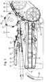
- packaging 10 details of a packaging machine are exemplified for packaging 10, namely cigarette packaging, shown. Specifically, they are soft cup packs, thus a type of cigarette packaging 10, at which a group of cigarettes from an inner blank of paper or tinfoil and a cigarette block from is wrapped in a paper cup.
- the packaging 10 has a cuboid shape with a large front wall 11, opposite rear wall 12 and elongated, narrow Side walls 13 and 14.
- the packaging 10 is in the present example in the exit area of a packaging machine.
- the packing 10 have left a drying turret and are transported by a belt conveyor 15. This is part a packaging machine, as described in detail in EP 605 838 is shown and described.
- the belt conveyor 15 conveys the packaging 10 in the correct position between carriers 16 such that the packaging 10 have a clear distance from each other in the conveying direction.
- the belt conveyor 15 consists of a toothed belt on an arcuate base 17 is guided and an arcuate Forming conveyor strand 18 for the packaging 10.
- the packages 10 are one by the belt conveyor 15 Abddyer 19 supplied. This transports the packaging 10 with the predetermined distance from each other Purpose, for example a packaging machine for attaching an outer covering made of foil.
- the Abddyer consists of an upper conveyor belt 20 and a lower conveyor belt 21. essentially horizontal conveying strands of these Conveyor belts 20 and 21, the packages 10 are transported, in such a way that the transverse, upward and bottom-facing side walls 13, 14 on the conveying strands the conveyor belts 20, 21 abut.
- the packaging 10 delivered by the belt conveyor 15 are not sent directly to the conveyor 19 passed, but via an intermediate conveyor in the form of a star wheel 22. This takes the packaging one after the other 10 from the conveyor strand 18 of the belt conveyor 15 and passes them to the conveyor 19.
- the screening unit 24 consists of two for each important sub-assemblies. It is about one for a removal conveyor for the packaging 10, the is designed here as a discharge wheel 26. On the other hand it is a conveyor system for the discharged Packaging 10.
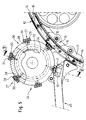
- the discharge wheel 26 is a roller-shaped structure with recordings 27 arranged along the circumference for one each to be discharged Packaging 10.
- the discharge wheel 26 is in one such position relative to the path of movement of the packaging 10 positioned that the packaging to be detected 10 through one of the receptacles 27 in the area of the radially outward directional, free packaging area can be detected, namely the large front wall 11.
- the receptacles 27 are each tangential in the area, thus by flattening formed bearing surfaces 28 of the Ausleuserads 26 arranged on this.
- the recordings 27 exist from organs that the packaging 10 by suction air, So capture and hold by negative pressure and suction.
- each receptacle 27 from several - here from three - suction heads, 29.
- the (three) suction heads 29 are in the area of the plane Bearing surface 28 in the axial direction of the discharge wheel 26 arranged side by side. In the example shown (Fig. 7) is the middle suction head 29 compared to the edge-side suction heads 29 arranged offset in the circumferential direction.
- the suction heads 29 consist of elastic material, in particular Rubber.
- each a central suction hole 30 - open outer circular contact surfaces 31 of the suction heads 29.
- the suction heads 29 When a packaging 10 is picked up by the discharge wheel 26 are the suction heads 29 with their contact surfaces 31 on the packing surface facing upwards or outwards on and are held by the negative pressure.
- the circular or cylindrical suction heads 29 here preferably designed as rubber-metal elements with a metallic support plate (not shown) and one on this attached, metallic threaded pin 69. This sits with an external thread in a threaded bore 64 of the bearing surface 28.
- the (central) suction bore 30 leads through the threaded pin 69 through to a radial connection bore 65 in the discharge wheel 26.
- the connection bores 65 of the suction heads 29 are interconnected by an axially parallel Cross bore 66.
- the common transverse bore 66 is via a radial bore 67 connected to an axially parallel bore 68, which in turn to a channel segment 32 in the area of a fixed one Support organ 33 leads.
- the channel segments 32 are in the as Support disc designed support member 33 as an arcuate, open grooves arranged (Fig. 5).
- the suction bores 30 are connected to a vacuum source.
- the receptacles 27 with regard to the takeover of packaging 10 separately are controllable.
- two concentrically arranged channel segments 32 and 34 provided.
- the radial bores 67 and this subsequent transverse bores 68 are positioned that a group of the receptacles 27 the radially outer Channel segment 32 and the other receptacles 27 the radial inner channel segment 34 are assigned.
- the order is made so that in the direction of rotation of the discharge wheel 26 the recordings 27 alternately one and the other Channel segment 32, 34 are assigned.
- the channel segments 32, 34 have their own shut-off valves with the common one Vacuum source connected. The shut-off valves are depending on the receptacle 27 to be acted on.
- the pot-shaped discharge wheel 26 is over a Drive shaft 35 connected to a drive wheel 36.
- the drive shaft 35 is in a support wall 37 of a machine frame stored.
- the drive wheel 36 is driven by a belt drive driven by toothed belt 38.
- the stationary support member 33 is non-rotatable by means of pin 39 mounted on the drive shaft 35 and by springs 40 supported elastically on the support wall 37.
- a thrust washer 41 positioned between the support organ 33 and the discharge wheel 26.
- the thrust washer 41 is made of a material with high abrasion resistance, for example made of carbon.
- the bore 68 leads through this thrust washer 41. It is tight the support member 33.
- the packaging 10 gripped by the discharge wheel 26 becomes through the receptacle 27 over a short conveyor distance, namely circular arc-shaped conveyor track, taken and a conveyor supplied for the discarded packaging 10. These will stored on a platform 42 and then transported on.
- the one acting on the suction elements is used Suction air of the recordings 27 controlled away.
- the packaging 10 in the storage area for a short time pressurized with compressed air, namely via the described Channel system for the transmission of negative pressure.
- channel segments are formed in the support member 33.
- This Channel segments are also designed as partial arcs and connected to a compressed air source. This will make one Safe and exact release and storage of the packaging 10 guaranteed above platform 42.
- Control of the compressed air to the receptacles 27 applies analogously to that Description in connection with the vacuum system.
- the Recordings 27 are alternately one and the other channel segment assigned.
- the platform 42 is the open top area of one Packing conveyor 45. This begins here immediately Neighborhood to the belt conveyor 15.
- the package conveyor 45 transports the discarded packaging 10, namely Faulty packs 23 and test packs 25, separately from the conveyor 19th
- the pack conveyor 45 is in this embodiment designed as a conveyor channel with a closed, rectangular Channel cross section.
- the packages 10 are inside of the pack conveyor 45 conveyed by means of compressed air.
- An air flow is via air nozzles 46, 47 in the direction of flow passed into the channel-shaped package conveyor 45.
- the present exemplary embodiment is a plurality of air nozzles 46, 47 in the conveying direction at a distance from each other on an upper wall 48 of the package conveyor 45 attached.
- Fig. 3 shows an embodiment of such an air nozzle 46, 47.
- One at an acute angle to the top wall 48 Directed nozzle channel 49 opens into the pack conveyor 45
- Nozzle channel 49 has a transverse air line 50 connected. This is connected to a compressed air source.
- the removed packages 10 are in the area of Packing conveyor 45 separated according to the type of packaging.
- the packaging conveyor 45 is connected a branch conveyor 51 at an acute angle.
- a switch 52 is installed, the the packaging 10 depending on the type of packaging in the packaging conveyor 45 transported on or in the branch conveyor 51 passes.
- Sample packs 25 are preferably the branch conveyor 51 fed.
- the switch 52 consists of a guide element 54 in the form a wedge-shaped, pointed or sharp body. This is in the region of the branch 53 within the channel-shaped Pack conveyor 45 movable, namely by a Pivot bearing 55 pivoted. In one end position (Fig. 2), the guide element 24 is positioned so that the packaging 10 or sample packs 25 on an upper sliding surface 56 get into the branch conveyor 51. In another Position in which a free, the platform 42 facing Is moved to an upper position, forms the guide element 54 a closure for the branch conveyor 51. Instead the pack conveyor 54 is released continuously.
- the Guide element 54 is actuated by a cylinder 57 a lever arm 58.
- Pack conveyor 45 and branch conveyor 51 are in a relative position arranged to the conveyor 19, through the mutual Disruptions can be avoided.
- Packing conveyor 45 and branch conveyor 51 are arranged above the discharge conveyor 19.
- the branch conveyor 51 extends above the Packing conveyor 45. This in turn is - seen in plan - Provided with an offset piece 59, so one sideways directional deflection. The end of the offset piece 59 is therefore laterally offset above the discharge conveyor 19 to this.
- Faulty packs 23 can get into a chute 60.
- the sample packs transported in the branch conveyor 51 25 can be removed from an open end 61.
- the conveyor system described are special monitoring bodies assigned. Located in the area of the pack conveyor 45 a light barrier 62 (the holder for this), by which the filling level of the package conveyor 45 is monitored becomes. Therefore, no further packaging 10 are discharged and fed to the pack conveyor 45, when it is filled. Also in the area of the branch conveyor 52 is a light barrier 63 in the area of the switch or Guide element 54 attached so that this is not adjusted can be, if there is packaging in this area.
Landscapes
- Engineering & Computer Science (AREA)
- Mechanical Engineering (AREA)
- Wrapping Of Specific Fragile Articles (AREA)
- Specific Conveyance Elements (AREA)
- Auxiliary Devices For And Details Of Packaging Control (AREA)
Claims (15)
- Dispositif de fabrication de paquets (10), en particulier de paquets de cigarettes, dont le contenu est enveloppé dans la zone d'un groupe de pliage dans au moins un flan en matériau d'emballage, comportant un transporteur sans fin (15) pour l'amenée des paquets (10) à un transporteur d'évacuation (19) qui évacue les paquets (10), des paquets (10) individuels choisis entièrement ou partiellement achevés pouvant être enlevés du flux de transport par soulèvement du transporteur sans fin (15) par un transporteur de prélèvement formé d'une roue de déséclusage soumise à rotation (26) et menés à un transporteur de paquets séparé (45), caractérisé par les caractéristiques suivantes :a) la roue de déséclusage (26) présente sur son pourtour plusieurs récepteurs placés à distance les uns des autres (27) pour la saisie ciblée de paquets (10) individuels,b) la roue de déséclusage (26) peut tourner en synchronisme avec le transporteur sans fin (15),c) pour la saisie d'un paquet (10), un récepteur (27) de la roue de déséclusage (26) associé à ce paquet (10) peut être activé en cas d'appui sur celui-ci.
- Dispositif selon la revendication 1, caractérisé par le fait que la roue de déséclusage (26), qui tourne autour d'un axe parallèle au plan de transport du transporteur sans fin (15), présente plusieurs récepteurs (27) placés à intervalles égaux le long de sa circonférence et pourvus d'organes d'aspiration, à savoir de têtes aspirantes (29), qui saisissent par aspiration le paquet (10) à recevoir dans la zone d'une face de celui-ci, en particulier d'une paroi avant de grande surface (11).
- Dispositif selon la revendication 2, caractérisé par le fait que les têtes aspirantes (29) sont entièrement ou partiellement en matière élastique, en particulier en caoutchouc, et présentent au moins un trou d'aspiration dirigé radialement (30), les trous d'aspiration débouchant dans la zone de surfaces d'appui extérieures radialement (31) des têtes aspirantes (29).
- Dispositif selon la revendication 3, caractérisé par le fait que plusieurs, en particulier trois, têtes aspirantes (29) sont placées les unes à côté des autres dans la direction axiale de la roue de déséclusage (26) dans la zone d'une surface radiale d'appui (28) de celle-ci.
- Dispositif selon la revendication 2 ou une des autres revendications, caractérisé par le fait que la roue de déséclusage (26) est mue à la même vitesse périphérique que le transporteur sans fin (15), les distances des têtes aspirantes (29) sur le pourtour de la roue de déséclusage (26) correspondant aux distances des paquets (10) entre eux déterminées sur le transporteur sans fin (15) par des entraíneurs (16) ou des éléments semblables.
- Dispositif selon la revendication 2 ou une des autres revendications, caractérisé par le fait que les têtes aspirantes (29) présentant des trous d'aspiration (30) peuvent être commandées en au moins deux groupes indépendamment l'un de l'autre pour la saisie de paquets (10), de préférence de façon telle que les trous d'aspiration (30) des têtes aspirantes (29) qui se suivent dans la direction circonférentielle de la roue de déséclusage (26) soient associés alternativement à des sources de dépression différentes et/ou à des vannes d'arrêt différentes pour la liaison à la source de dépression.
- Dispositif selon la revendication 6, caractérisé par le fait que plusieurs canaux d'air fixes reliés à la source de dépression, en particulier des segments de canal en arc de cercle (32, 34) formés sur un organe support fixe (33), sont associés aux différents trous d'aspiration (30) de façon telle que des trous d'aspiration (30) se suivant dans la direction de rotation soient associés alternativement à l'un et à l'autre segment de canal (32, 34).
- Dispositif selon la revendication 1 ou une des autres revendications, caractérisé par le fait que les paquets (10) à retirer peuvent être saisis dans la zone d'un chemin de transport en arc de cercle du transporteur sans fin d'allure correspondante (15) sur leur côté supérieur extérieur radialement par la roue de déséclusage (26) tournant dans un plan vertical au-dessus du transporteur sans fin (15), transportés le long d'un arc de cercle et déposés sur le transporteur de paquets (45), qui est placé dans le même plan que la roue de déséclusage (26) et le transporteur sans fin (15).
- Dispositif selon la revendication 3 ou une des autres revendications, caractérisé par le fait que, pour la libération de paquets (10) tenus sur la roue de déséclusage (26), en particulier pour leur pose sur une plate-forme (42) du transporteur de paquets (45), de l'air comprimé peut être envoyé dans les trous d'aspiration (30), en particulier de façon telle que les surfaces d'appui (28) qui se suivent dans la direction circonférentielle puissent être reliées alternativement à une source d'air comprimé par des vannes d'arrêt manoeuvrables séparément.
- Dispositif selon la revendication 1 ou une des autres revendications, caractérisé par le fait que le transporteur de paquets (45) pour l'évacuation des paquets (10) retirés est constitué d'un canal de transport de section fermée, et que les paquets (10) sont transportables à l'intérieur du transporteur de paquets en forme de canal (45) par un courant d'air, une zone d'entrée du transporteur de paquets étant constituée d'une plate-forme (42) pour la pose des paquets (10).
- Dispositif selon la revendication 10, caractérisé par le fait que sur le transporteur de paquets (45) sont montées, de préférence dans la zone d'une paroi supérieure (48), plusieurs buses à air (46, 47) qui se suivent dans la direction de transport et envoient dans le transporteur de paquets (45) un courant d'air dirigé dans la direction de transport.
- Dispositif selon la revendication 1 ou une des autres revendications, caractérisé par le fait qu'au transporteur de paquets (45) se joint dans la zone d'un embranchement (53) un transporteur en dérivation (51) pour l'évacuation de paquets (10), en particulier de paquets échantillons (25), vers un transporteur séparé.
- Dispositif selon la revendication 12, caractérisé par le fait que, dans la zone de l'embranchement (53) pour le transporteur en dérivation (51) est formé à l'intérieur du transporteur de paquets (45) un aiguillage (52), de préférence comportant un élément directeur basculant (54), pour conduire les paquets (10) soit au transporteur en dérivation (51), soit le long du transporteur de paquets (45).
- Dispositif selon l'une des revendications 12 et 13, caractérisé par le fait que le transporteur en dérivation (51) part du transporteur de paquets (45), qui est sensiblement rectiligne, vers le haut de façon telle qu'il soit dans un plan situé au-dessus du transporteur de paquets (45).
- Dispositif selon la revendication 1 ou une des autres revendications, caractérisé par le fait que le transporteur de paquets (45) s'étend au-dessus du transporteur d'évacuation (19), de préférence par une pièce de déport dirigée de côté (59), de façon telle qu'une extrémité libre du transporteur de paquets (45), vue dans la direction verticale, s'étende décalée latéralement du transporteur d'évacuation (19).
Applications Claiming Priority (2)
| Application Number | Priority Date | Filing Date | Title |
|---|---|---|---|
| DE19539417 | 1995-10-24 | ||
| DE19539417A DE19539417A1 (de) | 1995-10-24 | 1995-10-24 | Vorrichtung zum Herstellen von insbesondere Zigaretten-Verpackungen |
Publications (3)
| Publication Number | Publication Date |
|---|---|
| EP0770551A1 EP0770551A1 (fr) | 1997-05-02 |
| EP0770551B1 true EP0770551B1 (fr) | 1999-02-10 |
| EP0770551B2 EP0770551B2 (fr) | 2004-08-25 |
Family
ID=7775540
Family Applications (1)
| Application Number | Title | Priority Date | Filing Date |
|---|---|---|---|
| EP96116464A Expired - Lifetime EP0770551B2 (fr) | 1995-10-24 | 1996-10-15 | Dispositif pour la fabrication de paquets de cigarettes |
Country Status (6)
| Country | Link |
|---|---|
| US (1) | US5784855A (fr) |
| EP (1) | EP0770551B2 (fr) |
| JP (1) | JP4031074B2 (fr) |
| CN (1) | CN1059397C (fr) |
| BR (1) | BR9605214A (fr) |
| DE (2) | DE19539417A1 (fr) |
Cited By (1)
| Publication number | Priority date | Publication date | Assignee | Title |
|---|---|---|---|---|
| EP2735531A1 (fr) | 2012-11-27 | 2014-05-28 | Focke & Co. (GmbH & Co.) | Procédé et dispositif destinés à déplacer des paquets, notamment des paquets de cigarettes |
Families Citing this family (11)
| Publication number | Priority date | Publication date | Assignee | Title |
|---|---|---|---|---|
| IT1290696B1 (it) * | 1997-02-24 | 1998-12-10 | Gd Spa | Metodo e macchina per l'incarto di prodotti. |
| EP0941775B1 (fr) * | 1998-03-02 | 2005-10-26 | Focke & Co. (GmbH & Co. KG) | Méthode et dispositif pour examiner optiquement des paquets |
| DE19814932A1 (de) | 1998-04-03 | 2001-01-11 | Focke & Co | Zigarettenpackung sowie Verfahren und Vorrichtung zum Herstellen derselben |
| US6553743B1 (en) * | 1999-01-12 | 2003-04-29 | R.A. Jones & Co. Inc. | Rotary knife and transfer apparatus |
| DE19946787A1 (de) * | 1999-09-29 | 2001-04-05 | Focke & Co | Verfahren und Vorrichtung zur Diagnose von Maschinen |
| DE10135484A1 (de) | 2001-07-20 | 2003-01-30 | Philip Morris Prod | Verfahren und Einrichtung zur Wertrückgewinnung von ausgesonderten Zigarettenpackungen |
| DE102006058370A1 (de) * | 2006-12-08 | 2008-06-12 | Focke & Co.(Gmbh & Co. Kg) | Verfahren und Vorrichtung zum Herstellen von Zigarettenpackungen |
| BR112013023988A2 (pt) * | 2011-03-23 | 2016-12-13 | Bosch Gmbh Robert | método para o acondicionamento de produtos, notadamente partes de chocolate ou similares, e equipamento para a aplicação do método |
| DE102011113704A1 (de) | 2011-08-02 | 2013-02-07 | Focke & Co. (Gmbh & Co. Kg) | Verfahren und Vorrichtung zur optischen Prüfung von bei der Herstellung und/oder Verpackung von Zigaretten zu prüfenden Objekten |
| DE102011120721A1 (de) | 2011-12-12 | 2013-06-13 | Focke & Co. (Gmbh & Co. Kg) | Verfahren und Vorrichtung zum optischen Prüfen von bei der Herstellung und/oder Verpackung von Zigaretten zu prüfenden Objekten |
| CN110844160B (zh) * | 2019-10-15 | 2021-10-22 | 上海烟草机械有限责任公司 | 一种用于香烟包装的内盒烟组入盒包装工艺 |
Family Cites Families (18)
| Publication number | Priority date | Publication date | Assignee | Title |
|---|---|---|---|---|
| GB1203223A (en) * | 1966-09-19 | 1970-08-26 | Hauni Werke Koerber & Co Kg | Method and machine for packaging or wrapping block-shaped articles |
| GB1220672A (en) † | 1967-02-02 | 1971-01-27 | Frederick Southcott | Improvements in or relating to article handling apparatus |
| US3517477A (en) * | 1967-10-06 | 1970-06-30 | Molins Machine Co Ltd | Article handling apparatus |
| US3590556A (en) * | 1968-01-05 | 1971-07-06 | Heinz Focke | Machine for packing of cigarettes in soft packets |
| DE1958738A1 (de) * | 1969-11-22 | 1971-06-03 | Hauni Werke Koerber & Co Kg | Verfahren und Vorrichtung zum Foerdern von Tabakartikeln |
| IT938661B (it) * | 1971-09-07 | 1973-02-10 | Amf Sasib | Dispositivo immagazzinatore alimn tatore per il collegamento diretto selettivo tra una macchina continua confezionatrice di sigarette o un applicatore di filtri ad una impac chettatrice |
| US3822008A (en) * | 1973-02-01 | 1974-07-02 | Jones & Co Inc R A | Transfer apparatus for packaging machine |
| IT982254B (it) * | 1973-03-05 | 1974-10-21 | Gd Spa | Apparecchiatura di uscita dei pro dotti da una linea di incarto e confezionamento di detti prodot ti particolarmente pacchetti di sigarette e simili |
| IT1147355B (it) * | 1981-05-19 | 1986-11-19 | Sasib Spa | Dispositivo per lo scarto di pacchetti difettosi |
| IT1169164B (it) † | 1983-02-08 | 1987-05-27 | Gd Spa | Gruppo campionatore di uscita di una macchina mettifiltro |
| IT1192041B (it) * | 1986-05-27 | 1988-03-31 | Gd Spa | Dispositivo di uscita di una linea di impacchettamento |
| US4760909A (en) † | 1986-11-17 | 1988-08-02 | Dudley Peter B | Suction diverter |
| DE3701768A1 (de) * | 1987-01-22 | 1988-08-04 | Focke & Co | Verpackungsmaschine mit trockenrevolver |
| DE3802644C2 (de) * | 1988-01-29 | 1999-10-07 | Focke & Co | Verfahren und Vorrichtung zum Herstellen von Klappschachteln für Zigaretten |
| IT1240127B (it) * | 1990-03-07 | 1993-11-27 | Cavanna Spa | Dispositivo per convogliare articoli, particolarmente per impianti automatici di confezionamento. |
| DE4134438C2 (de) * | 1991-10-18 | 1994-11-10 | Leifeld & Lemke Maschf | Vorrichtung zum Verteilen von Behältern auf mehrere Spuren eines Förderers |
| DE4300149A1 (de) † | 1993-01-08 | 1994-07-14 | Focke & Co | Vorrichtung zum Herstellen von Zigaretten-Packungen |
| IT1264199B1 (it) * | 1993-09-01 | 1996-09-23 | Gd Spa | Convogliatore per prodotti, in particolare pacchetti di sigarette. |
-
1995
- 1995-10-24 DE DE19539417A patent/DE19539417A1/de not_active Withdrawn
-
1996
- 1996-10-15 EP EP96116464A patent/EP0770551B2/fr not_active Expired - Lifetime
- 1996-10-15 DE DE59601293T patent/DE59601293D1/de not_active Expired - Fee Related
- 1996-10-23 US US08/735,636 patent/US5784855A/en not_active Expired - Fee Related
- 1996-10-23 BR BR9605214A patent/BR9605214A/pt not_active IP Right Cessation
- 1996-10-24 CN CN96114439A patent/CN1059397C/zh not_active Expired - Fee Related
- 1996-10-24 JP JP28239196A patent/JP4031074B2/ja not_active Expired - Fee Related
Cited By (1)
| Publication number | Priority date | Publication date | Assignee | Title |
|---|---|---|---|---|
| EP2735531A1 (fr) | 2012-11-27 | 2014-05-28 | Focke & Co. (GmbH & Co.) | Procédé et dispositif destinés à déplacer des paquets, notamment des paquets de cigarettes |
Also Published As
| Publication number | Publication date |
|---|---|
| DE19539417A1 (de) | 1997-04-30 |
| CN1059397C (zh) | 2000-12-13 |
| BR9605214A (pt) | 1998-07-21 |
| DE59601293D1 (de) | 1999-03-25 |
| JPH09193909A (ja) | 1997-07-29 |
| EP0770551A1 (fr) | 1997-05-02 |
| EP0770551B2 (fr) | 2004-08-25 |
| CN1156679A (zh) | 1997-08-13 |
| JP4031074B2 (ja) | 2008-01-09 |
| US5784855A (en) | 1998-07-28 |
Similar Documents
| Publication | Publication Date | Title |
|---|---|---|
| EP0605838B1 (fr) | Dispositif pour la fabrication de paquets de cigarettes | |
| EP0444547B1 (fr) | Méthode et dispositif pour convoyer des bandes de fermeture en vue de les transférer à des paquets | |
| DE2510094C2 (de) | Vorrichtung zum Drehen von quaderförmigen Gegenständen um eine senkrechte Achse bei deren Transport auf einer Förderstrecke | |
| EP2560602B1 (fr) | Dispositif pour le remplissage et la fermeture de capsules remplies d'au moins une matière de remplissage | |
| EP0770551B1 (fr) | Dispositif pour la fabrication de paquets de cigarettes | |
| EP0638478B1 (fr) | Dispositif pour tirer des récipients d'emballages de transport | |
| EP1216939A1 (fr) | Dispositif de transport d'objets comprenant une réserve d'accumulation | |
| EP2493762B1 (fr) | Procédé et dispositif pour manipuler des pièces découpées en matériau d'emballage pour des paquets de cigarettes | |
| EP0529689B1 (fr) | Dispositif pour transférer des paquets parallelépipédiques | |
| DE19753019A1 (de) | Verfahren und Vorrichtung zum Handhaben von insbesondere Folien-Weichpackungen | |
| DE2518524C2 (de) | Einrichtung zum Prüfen von Arzneikapseln | |
| DE69802165T2 (de) | Verfahren und vorrichtung zum anbringen von lösbaren etiketten auf annähernd quaderförmigen verpackungen | |
| EP0645308A1 (fr) | Procédé et machine d'emballage pour décharger des récipients des caisses de transport | |
| EP1428761B1 (fr) | Procédé et dispositif de manipulation de feuilles, en particulier de coupons | |
| DE3620717A1 (de) | Ein- oder auspackmaschine | |
| EP0596387B1 (fr) | Dispositif pour transporter des paquets de cigarettes | |
| DE102008018224A1 (de) | Verfahren und Vorrichtung zur Übergabe von kleinstückigen, insbesondere mit einem Stiel versehenen Produkten an eine Längsfördereinrichtung | |
| DE60306680T2 (de) | Zufuhrvorrichtung | |
| DE69722057T2 (de) | Vorrichtung zum Fördern von Paketen | |
| WO1999012841A1 (fr) | Dispositif pour fermer des contenants a boissons avec des elements de fermeture | |
| EP4438532A1 (fr) | Procédé et dispositif pour former des piles d'emballages | |
| EP2134609B1 (fr) | Procede et dispositif pour former des lots de paquets | |
| DE4306110C2 (de) | Vorrichtung zum Zusammenführen mehrerer Deckelstränge zu einem Deckelstrang und/oder zum Aufteilen eines Deckelstrangs in mehrere Deckelstränge | |
| DE102020104063B4 (de) | Fördervorrichtung für vereinzelte Erzeugnisse | |
| EP3676185B1 (fr) | Dispositif et procédé de fabrication de paquets de cigarettes |
Legal Events
| Date | Code | Title | Description |
|---|---|---|---|
| PUAI | Public reference made under article 153(3) epc to a published international application that has entered the european phase |
Free format text: ORIGINAL CODE: 0009012 |
|
| 17P | Request for examination filed |
Effective date: 19970301 |
|
| AK | Designated contracting states |
Kind code of ref document: A1 Designated state(s): DE FR GB IT |
|
| 17Q | First examination report despatched |
Effective date: 19970825 |
|
| GRAG | Despatch of communication of intention to grant |
Free format text: ORIGINAL CODE: EPIDOS AGRA |
|
| GRAG | Despatch of communication of intention to grant |
Free format text: ORIGINAL CODE: EPIDOS AGRA |
|
| GRAH | Despatch of communication of intention to grant a patent |
Free format text: ORIGINAL CODE: EPIDOS IGRA |
|
| GRAH | Despatch of communication of intention to grant a patent |
Free format text: ORIGINAL CODE: EPIDOS IGRA |
|
| GRAA | (expected) grant |
Free format text: ORIGINAL CODE: 0009210 |
|
| AK | Designated contracting states |
Kind code of ref document: B1 Designated state(s): DE FR GB IT |
|
| GBT | Gb: translation of ep patent filed (gb section 77(6)(a)/1977) |
Effective date: 19990210 |
|
| REF | Corresponds to: |
Ref document number: 59601293 Country of ref document: DE Date of ref document: 19990325 |
|
| ITF | It: translation for a ep patent filed | ||
| ET | Fr: translation filed | ||
| PLBQ | Unpublished change to opponent data |
Free format text: ORIGINAL CODE: EPIDOS OPPO |
|
| PLBI | Opposition filed |
Free format text: ORIGINAL CODE: 0009260 |
|
| PLBF | Reply of patent proprietor to notice(s) of opposition |
Free format text: ORIGINAL CODE: EPIDOS OBSO |
|
| 26 | Opposition filed |
Opponent name: G.D S.P.A. Effective date: 19991109 |
|
| PLBF | Reply of patent proprietor to notice(s) of opposition |
Free format text: ORIGINAL CODE: EPIDOS OBSO |
|
| PLBF | Reply of patent proprietor to notice(s) of opposition |
Free format text: ORIGINAL CODE: EPIDOS OBSO |
|
| PLAW | Interlocutory decision in opposition |
Free format text: ORIGINAL CODE: EPIDOS IDOP |
|
| APAC | Appeal dossier modified |
Free format text: ORIGINAL CODE: EPIDOS NOAPO |
|
| APAE | Appeal reference modified |
Free format text: ORIGINAL CODE: EPIDOS REFNO |
|
| APAC | Appeal dossier modified |
Free format text: ORIGINAL CODE: EPIDOS NOAPO |
|
| APAE | Appeal reference modified |
Free format text: ORIGINAL CODE: EPIDOS REFNO |
|
| REG | Reference to a national code |
Ref country code: GB Ref legal event code: IF02 |
|
| APBU | Appeal procedure closed |
Free format text: ORIGINAL CODE: EPIDOSNNOA9O |
|
| PUAH | Patent maintained in amended form |
Free format text: ORIGINAL CODE: 0009272 |
|
| STAA | Information on the status of an ep patent application or granted ep patent |
Free format text: STATUS: PATENT MAINTAINED AS AMENDED |
|
| 27A | Patent maintained in amended form |
Effective date: 20040825 |
|
| AK | Designated contracting states |
Kind code of ref document: B2 Designated state(s): DE FR GB IT |
|
| GBTA | Gb: translation of amended ep patent filed (gb section 77(6)(b)/1977) | ||
| ET3 | Fr: translation filed ** decision concerning opposition | ||
| APAH | Appeal reference modified |
Free format text: ORIGINAL CODE: EPIDOSCREFNO |
|
| PGFP | Annual fee paid to national office [announced via postgrant information from national office to epo] |
Ref country code: DE Payment date: 20071025 Year of fee payment: 12 |
|
| PGFP | Annual fee paid to national office [announced via postgrant information from national office to epo] |
Ref country code: FR Payment date: 20081014 Year of fee payment: 13 |
|
| PG25 | Lapsed in a contracting state [announced via postgrant information from national office to epo] |
Ref country code: DE Free format text: LAPSE BECAUSE OF NON-PAYMENT OF DUE FEES Effective date: 20090501 |
|
| REG | Reference to a national code |
Ref country code: FR Ref legal event code: ST Effective date: 20100630 |
|
| PG25 | Lapsed in a contracting state [announced via postgrant information from national office to epo] |
Ref country code: FR Free format text: LAPSE BECAUSE OF NON-PAYMENT OF DUE FEES Effective date: 20091102 |
|
| PGFP | Annual fee paid to national office [announced via postgrant information from national office to epo] |
Ref country code: IT Payment date: 20101018 Year of fee payment: 15 Ref country code: GB Payment date: 20101013 Year of fee payment: 15 |
|
| GBPC | Gb: european patent ceased through non-payment of renewal fee |
Effective date: 20121015 |
|
| PG25 | Lapsed in a contracting state [announced via postgrant information from national office to epo] |
Ref country code: GB Free format text: LAPSE BECAUSE OF NON-PAYMENT OF DUE FEES Effective date: 20121015 |
|
| PG25 | Lapsed in a contracting state [announced via postgrant information from national office to epo] |
Ref country code: IT Free format text: LAPSE BECAUSE OF NON-PAYMENT OF DUE FEES Effective date: 20121015 |