EP1428761B1 - Procédé et dispositif de manipulation de feuilles, en particulier de coupons - Google Patents
Procédé et dispositif de manipulation de feuilles, en particulier de coupons Download PDFInfo
- Publication number
- EP1428761B1 EP1428761B1 EP03027661A EP03027661A EP1428761B1 EP 1428761 B1 EP1428761 B1 EP 1428761B1 EP 03027661 A EP03027661 A EP 03027661A EP 03027661 A EP03027661 A EP 03027661A EP 1428761 B1 EP1428761 B1 EP 1428761B1
- Authority
- EP
- European Patent Office
- Prior art keywords
- coupons
- coupon
- conveyor
- conveying
- feeder
- Prior art date
- Legal status (The legal status is an assumption and is not a legal conclusion. Google has not performed a legal analysis and makes no representation as to the accuracy of the status listed.)
- Expired - Lifetime
Links
- 238000000034 method Methods 0.000 title claims abstract description 11
- 238000004806 packaging method and process Methods 0.000 claims abstract description 17
- 235000019504 cigarettes Nutrition 0.000 claims abstract description 10
- 239000000969 carrier Substances 0.000 claims abstract description 7
- 230000032258 transport Effects 0.000 claims description 12
- 230000001154 acute effect Effects 0.000 claims description 4
- 238000006073 displacement reaction Methods 0.000 claims 1
- 238000012856 packing Methods 0.000 claims 1
- 230000000087 stabilizing effect Effects 0.000 claims 1
- 238000007792 addition Methods 0.000 abstract 2
- 239000011888 foil Substances 0.000 description 4
- 239000003292 glue Substances 0.000 description 4
- 208000023514 Barrett esophagus Diseases 0.000 description 1
- 230000004888 barrier function Effects 0.000 description 1
- 230000005540 biological transmission Effects 0.000 description 1
- 230000015572 biosynthetic process Effects 0.000 description 1
- 230000008859 change Effects 0.000 description 1
- 230000003750 conditioning effect Effects 0.000 description 1
- 238000004519 manufacturing process Methods 0.000 description 1
- 238000012858 packaging process Methods 0.000 description 1
- 238000012536 packaging technology Methods 0.000 description 1
- 230000002093 peripheral effect Effects 0.000 description 1
- 230000004044 response Effects 0.000 description 1
Images


Classifications
-
- B—PERFORMING OPERATIONS; TRANSPORTING
- B65—CONVEYING; PACKING; STORING; HANDLING THIN OR FILAMENTARY MATERIAL
- B65B—MACHINES, APPARATUS OR DEVICES FOR, OR METHODS OF, PACKAGING ARTICLES OR MATERIALS; UNPACKING
- B65B61/00—Auxiliary devices, not otherwise provided for, for operating on sheets, blanks, webs, binding material, containers or packages
- B65B61/20—Auxiliary devices, not otherwise provided for, for operating on sheets, blanks, webs, binding material, containers or packages for adding cards, coupons or other inserts to package contents
-
- B—PERFORMING OPERATIONS; TRANSPORTING
- B65—CONVEYING; PACKING; STORING; HANDLING THIN OR FILAMENTARY MATERIAL
- B65H—HANDLING THIN OR FILAMENTARY MATERIAL, e.g. SHEETS, WEBS, CABLES
- B65H29/00—Delivering or advancing articles from machines; Advancing articles to or into piles
- B65H29/12—Delivering or advancing articles from machines; Advancing articles to or into piles by means of the nip between two, or between two sets of, moving tapes or bands or rollers
-
- B—PERFORMING OPERATIONS; TRANSPORTING
- B65—CONVEYING; PACKING; STORING; HANDLING THIN OR FILAMENTARY MATERIAL
- B65H—HANDLING THIN OR FILAMENTARY MATERIAL, e.g. SHEETS, WEBS, CABLES
- B65H31/00—Pile receivers
- B65H31/24—Pile receivers multiple or compartmented, e.d. for alternate, programmed, or selective filling
-
- B—PERFORMING OPERATIONS; TRANSPORTING
- B65—CONVEYING; PACKING; STORING; HANDLING THIN OR FILAMENTARY MATERIAL
- B65H—HANDLING THIN OR FILAMENTARY MATERIAL, e.g. SHEETS, WEBS, CABLES
- B65H35/00—Delivering articles from cutting or line-perforating machines; Article or web delivery apparatus incorporating cutting or line-perforating devices, e.g. adhesive tape dispensers
- B65H35/02—Delivering articles from cutting or line-perforating machines; Article or web delivery apparatus incorporating cutting or line-perforating devices, e.g. adhesive tape dispensers from or with longitudinal slitters or perforators
-
- B—PERFORMING OPERATIONS; TRANSPORTING
- B65—CONVEYING; PACKING; STORING; HANDLING THIN OR FILAMENTARY MATERIAL
- B65H—HANDLING THIN OR FILAMENTARY MATERIAL, e.g. SHEETS, WEBS, CABLES
- B65H2301/00—Handling processes for sheets or webs
- B65H2301/30—Orientation, displacement, position of the handled material
- B65H2301/33—Modifying, selecting, changing orientation
- B65H2301/332—Turning, overturning
- B65H2301/3321—Turning, overturning kinetic therefor
- B65H2301/33212—Turning, overturning kinetic therefor about an axis parallel to the direction of displacement of material
-
- B—PERFORMING OPERATIONS; TRANSPORTING
- B65—CONVEYING; PACKING; STORING; HANDLING THIN OR FILAMENTARY MATERIAL
- B65H—HANDLING THIN OR FILAMENTARY MATERIAL, e.g. SHEETS, WEBS, CABLES
- B65H2301/00—Handling processes for sheets or webs
- B65H2301/40—Type of handling process
- B65H2301/44—Moving, forwarding, guiding material
- B65H2301/445—Moving, forwarding, guiding material stream of articles separated from each other
- B65H2301/4454—Merging two or more streams
-
- B—PERFORMING OPERATIONS; TRANSPORTING
- B65—CONVEYING; PACKING; STORING; HANDLING THIN OR FILAMENTARY MATERIAL
- B65H—HANDLING THIN OR FILAMENTARY MATERIAL, e.g. SHEETS, WEBS, CABLES
- B65H2404/00—Parts for transporting or guiding the handled material
- B65H2404/20—Belts
- B65H2404/26—Particular arrangement of belt, or belts
- B65H2404/261—Arrangement of belts, or belt(s) / roller(s) facing each other for forming a transport nip
-
- B—PERFORMING OPERATIONS; TRANSPORTING
- B65—CONVEYING; PACKING; STORING; HANDLING THIN OR FILAMENTARY MATERIAL
- B65H—HANDLING THIN OR FILAMENTARY MATERIAL, e.g. SHEETS, WEBS, CABLES
- B65H2701/00—Handled material; Storage means
- B65H2701/10—Handled articles or webs
- B65H2701/19—Specific article or web
- B65H2701/1936—Tickets or coupons
Definitions
- the invention relates to a method for handling blanks, in particular for supplying print carriers, coupons or the like as an addition to a pack - cigarette pack. Furthermore, the invention relates to a device for carrying out the method.
- a foil outer wrapper incorporates the coupon into the package so that the coupon is available by removing the outer wrapper when the package is in use.
- the object of the invention is to integrate the handling of the coupons into the packaging process in such a way that the coupons can be combined with the pack without impairing the (high) performance of packaging machines.
- the handling of the coupons in the coupon applicator can be done in different ways.
- a special feature is the introduction of the coupons in a coupon magazine with at least one supply shaft.
- the coupon magazine, the coupons are removed individually by the appropriately trained coupon applicator.
- a coupon applicator designed in a special way is provided, which immediately receives the incoming coupons and feeds the packs without interruption of the (continuous) transport.
- the device according to the invention includes that the coupons can be transported in the region of a packaging machine by a coupon conveyor, either to a coupon magazine or directly to a coupon applicator.
- the wrapping machine is preferably for mounting an outer wrapping of foil to cigarette packs ("cello"), placing the coupons on an upwardly directed rear side of the cigarette packs and then surrounding the formed unit in a conventional manner by the foil.
- the formation of the coupon magazine on the one hand and the immediately loaded coupon applicant on the other hand each form a special feature.
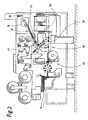
- each package 10 is to be accompanied by an optional folded blank with printing, namely a coupon 11, 12.
- the combination of the coupons 11, 12 with the packs 10 takes place in the region of a packaging machine for the attachment of an outer wrapping of foil to the pack 10.
- the coupon 11, 12 is placed on an upper side 13 of the pack 10 and surrounded together with the pack 10 of the outer sheath.
- the coupon 11, 12 is to be attached to a rear side of the pack 10.
- the coupons 11, 12 are produced by a coupon unit 14 of known type.
- the coupon unit 14 is designed such that double coupons 15 are produced and these are severed centrally with the aid of a cutter disk 16. This results in two adjacent coupons 11, 12 (FIG. 3).
- the coupon unit 14 is positioned - preferably as a separate unit - on a rear side of the packaging machine.
- the coupons 11, 12 are received outside the packaging machine by a coupon conveyor 17 and fed through a recess 18 in the packaging machine the front area, namely in a plane above a conveyor track 19 for the packs 10.
- the coupon conveyor 17 consists of several cooperating or to each other subsequent belt conveyors, which cause an approximately rectangular deflection of the coupons 11, 12 in the region of the packaging machine (FIGS. 1, 3).
- the coupons 11, 12 are supplied by a above the conveyor track 19 of the packs 10 arranged (coupon) trailer 20, 21 of the respective pack 10 and placed on the top 13. There are two conceptually different designs possible.
- the coupons 11, 12 can be supplied by the coupon conveyor 17 a coupon magazine 22 and stored in this. Individual coupons 11, 12 are removed by the trailer 20 (FIG. 2) from the coupon magazine 22 and fed to the respective package 10.
- the trailer 20 is formed in this embodiment in a conventional manner.
- the coupons 11, 12 may be fed directly to the trailer 21 by the coupon conveyor 17 and transferred therefrom to the package 10.
- the trailer 21 is formed in a special way (Fig. 7, Fig. 8).
- the coupon conveyor 17 has, on the one hand, the task of transporting the coupons 11, 12 after being taken over by the coupon unit 14 over a longer conveying path.
- the coupon conveyor 17 is designed according to FIG. 3 such that the two coupons 11, 12 which are fed next to one another are brought into an offset relative position during transport and finally into a successive relative position. This result is caused by temporarily different conveying speed of the two coupons 11, 12.
- Transfer belts 23, 24 adjoining the coupon unit 14 are driven at different conveying speeds, so that the offset of the coupons 11, 12 resulting from FIG. 3 is established.
- the transfer belt 24 arranged on the right here runs at a faster speed than the takeover belt 23.
- Each transfer belt 23, 24 consists of two interacting single belts. These are in each case with conveyor belts to each other, wherein the coupons 11, 12 are positioned and fixed between the mutually facing counselertrumen. Furthermore, the (two) takeover straps 23, 24 by appropriate arrangement of pulleys 25, 26 shaped so that the coupons 11, 12 are turned during transport by 90 °. The coupons 11, 12 are fed lying in a horizontal plane and turned during transport through the transfer straps 23, 24 in an upright plane.
- the intermediate conveyor 27 consists of converging guide members, which supply the coupons 11, 12 an entry area of the connecting conveyor 28. These are sidebands 29, which form converging conveying runs due to deflection rollers with different diameters. Inner guide members, namely inner bands 30 with likewise converging straps, are located between the two side straps 29, the inner straps 30 having wedge-shaped deflection pieces 31 at an end facing the connecting conveyor 28.
- the coupons 11, 12 fed in two spaced-apart webs are combined on the other hand between side band 29 on the one hand and inner band 30 on the other hand, and successively transferred to the common connecting conveyor 28.
- This also consists of two bands or straps, the coupons 11, 12 are transported fixed transported between the facing each other.
- the connecting conveyor 28 transfers the coupons 11, 12 - in a further vertical conveying plane - to a Umlenkwhier 32. This promotes the coupons 11, 12 in a 90 ° offset or deflected direction.
- the Umlenkwhier 32 consists of an inner conveyor 33 and an angular outer conveyor 34. Both conveyors 33, 34 are formed by straps, which are guided over three guide rollers. A middle guide roller 35 of the inner conveyor 33 causes the change in direction during transport of the coupons 11, 12.
- the straps or belts of the inner conveyor 33 are located directly on the guide roller 35 at.
- An angled conveying strand of the outer conveyor 34 is also indirectly on the guide roller 35, namely on the belt of the inner conveyor 33. In between, the coupons 11, 12 are transported.
- Deflection rollers 39, 40 are offset with respect to the axes of rotation by 90 ° to each other, so that the individual straps 37, 38 are turned from an upright level at the inlet side in a horizontal plane in the region of the guide roller 40. Accordingly, the coupons 11 are turned to a horizontal position.
- coupon magazine 22 in the embodiment shown. It consists of two shafts 42, 43 offset from the final conveyor 41. These are arranged in an upright position and each serve to receive a coupon stack 44. Coupons 11, 12 are taken from the coupon magazine 22 or each shaft 42, 43 at the bottom in succession , The removal member or the trailer 20 is conventional.
- the supplied from the coupon conveyor 17 coupons 11, 12 are supplied to one or the other shaft 42, 43 by sideways movement as needed.
- the level of the coupons 11, 12 in the shafts 42, 43, ie the height of the coupon stack 44 is checked, for example by light barriers. If the height of a coupon stack 44 drops below a certain level, coupons 11, 12 are additionally conveyed into the relevant shaft 42, 43.
- a coupon distributor 45 is arranged between the shafts 42, 43, in continuation of the conveying direction of the final conveyor 42. This consists of two distributor elements, namely conveyor rollers 46 and 47. The lower conveyor roller 47 is disposed below the Zu busyebene the coupons 11, 12 and the upper conveyor roller 46 above.
- the conveyor rollers 46, 47 are provided along the circumference with holes 49.
- the hollow conveyor rollers 46, 47 are connected to an air unit (not shown), in such a way that the conveyor rollers 46, 47 can alternatively be supplied with negative pressure, ie suction air or with overpressure, ie compressed air. Furthermore, the conveyor rollers 46, 47 are driven in opposite directions.
- the (right) shaft 43 is to be supplied with coupons 11, 12.
- the (upper) conveying roller 46 is acted upon by suction, so that the incoming coupons 11, 12 abut with a partial area on the circumference of the conveying roller 46.
- the system of the coupons 11, 12 on the circumference of the conveying roller 46 is supported by out of the holes 49 of the other (lower) conveyor roller 47 escaping compressed air.
- Both conveyor rollers 46, 47 are of a guide or a housing 50, 51 surrounded. This only releases a small, limited area of the circumference of the conveyor rollers 46, 47 in the area of the intermediate space 48.
- a portion of the coupons 11, 12 is in each case on one or the other housing 50, 51, so that the coupons 11, 12 with peeling from the circumference of the respective conveying roller 46, 47 to one or the other shaft 42, 43 are supplied. If the other shaft 42 is to be supplied, there is a reversal in the supply of suction air and compressed air, such that the coupons 11, 12 abut the circumference of the lower conveyor roller 47 and are fed through this the shaft 42.
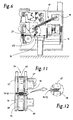
- the coupons 11, 12 may be fed directly from the coupon conveyor 17 to the specially constructed trailer 21.
- This consists of at least one conveyor for the coupons 11, 12, in this case a Materialslegergurt 52, which is designed so that the incoming coupons 11, 12 are transported in exact accordance with the conveying movement of the packs 10 and transferred to the associated pack 10 ,
- the trailer 21 and its Auflegergurt 52 is therefore driven in response to the central machine drive or is connected to this machine drive.
- the coupons 11, 12 on the attachment belt 52 have an exact relative position, which is matched to the conveying movement of the packs 10.
- the Auflegergurt 52 - preferably a toothed belt - driver 53 for each coupon 11, 12. Their transfer to the trailer 21 is carried out so that at the latest when handing over the coupons 11, 12 is given to the pack 10 a system on the associated driver 53.
- the trailer 21 and its Auflegergurt 52 connects directly to the coupon conveyor 17.
- This is formed in a similar manner as in the embodiment of FIG. 3.
- the final conveyor 41 is replaced by a transfer conveyor 54, which consists of a top flange 55 and a bottom flange 56.
- the latter is extended as a conveyor to the area of the Auflegers 21 and the Aufleggurts 52 to form a covering area.
- a deflection roller 57 of the lower belt 56 abuts (indirectly) on a conveying strand of the Aufleggurts 52.
- the coupons 11, 12 in one-lane operation of the packaging machine by a single trailer 21 the packs 10 are supplied.
- two carriers 21 are arranged side by side and associated with parallel conveyor tracks 19 for packs 10 (Fig. 1).
- the juxtaposed trailer 21 are supplied in this case by separate coupon conveyor 17, the each associated with a trailer 21.
- the coupon conveyor 17 is designed in a similar manner as in the embodiment of FIG. 3, but without the proposed there combination of the two simultaneously manufactured coupons 11, 12 on a common conveyor (connecting conveyor 28). Rather, the coupons 11 on the one hand and 12 on the other hand fed by individual coupon conveyor 17 to the two Auflegern 21.
- the trailer 21 is designed so that in a (upper) area following the transfer conveyor 54, a continuation of the predetermined conveying direction of the coupons 11, 12 takes place. Furthermore, it is provided that a (lower) the packs 10 facing end portion of the hanger 21 ensures an obliquely downward and in the conveying direction of the packs 10 facing feeding the coupons 11, 12 to the packs 10.
- a predetermined height of the trailer 21 is zigzag-shaped with an upper receiving leg 58, an adjoining at an (acute) angle intermediate leg 59 and turn at an opposite (acute) angle to the intermediate leg 59 directed transfer limb 60. The latter is at an acute angle to the movement path of the packs 10 and in the direction of movement thereof pointing.
- the Auflegergurt 52 follows this contour of the Auflegers 21 by appropriately staggered deflection rollers.
- the coupons 11, 12 are transported in the region of the receiving leg 58 and the transfer leg 60 each at a lower strand of the Aufleggurts 52.
- a stationary guide 61 is provided, which follows the contour of the Auflegers 21 or in close proximity to a conveying strand of the Aufleggurts 52.
- the guide 61 consists, as shown in FIG. 9, of two spaced-apart webs. In certain areas of the Aufleggurts 52 and the conveying strand are the coupons 11, 12 on the guide 61 slidably. In the entry region, namely in the region of an upper deflection roller 62, the coupons 11, 12 are introduced between Auflegergurt 52 and guide 61.
- the sequence of movements is controlled so that the respective coupon 11, 12 is introduced with a certain lead in front of the associated driver 53 (FIG. 7).
- By speed difference or by conditioning the coupons 11, 12 on the guide 61 follows the driver 53 and detects the coupon 11, 12 in precise relative position.
- a separate, circumferential transfer member for placing the coupons 11, 12 is provided on the top 13 of the packs 10.
- the Andschreibrad 63 which is arranged on an axle or (drive) shaft for pulleys 64 for Auflegergurt 52.
- the Auflegergurt 52 consists of two spaced apart parallel Einzelgurten (timing belt) with correspondingly spaced deflection rollers.
- the Andschreibrad 63 is disposed between the end-side guide rollers 64 and has a significantly larger diameter than these guide rollers 64.
- the supplied from the conveying strand of the Auflaggurts 52 coupon 11, 12 is lifted by the position and size of the Andschreibrades 63 of the Auflegergurt 52 and along the Promoted circumference of the Andschreibrades 63 and applied to the package 10 (Fig. 8).
- the guide 61 is designed by an arcuate bulge so that it is adapted to the contour of the Andschreibrades 63.
- the Andschreibrad 63 is rotatably driven by the Auflegergurt 52 with, so that the coupons 11, 12 are transmitted during the rotational movement of the Andschreibrades 63.
- the coupons 11, 12 are fixed with glue on the upper side 13 of the pack 10.
- a glue unit 65 with glue nozzle is provided, which provides a side of the coupons 11, 12 exposed during the transport of the coupons 11, 12 to the package 10 during the passage of glue, namely in the region of the intermediate limb 59 in which the relevant side of the coupons 11, 12 (obliquely) facing upward.
- the packs 10, which are equipped with coupons 11, 12, are fed along the conveying track 19 to a cutting unit 66 which holds a blank for the outer wrapping and wraps around the pack 10.
- the completion of the outer sheath takes place in a known manner.
- Another special feature is that the possibly multiply folded coupons 11, 12 are stabilized during transport in terms of design, ie in particular with regard to the folding by transfer of pressure by means of separate pressure elements.
- These are pressure rollers or pressure disks 67, 68 on both sides of the path of movement of the coupons 11, 12.
- the pressure elements or pressure disks 67, 68 are arranged in pairs on both sides of the path of movement of the coupons 11, 12, in lateral areas , namely in the region of folds or folding edges, which are compressed by the pressure writings 67, 68 arranged at a small distance from one another with their peripheral surfaces.
- the pressure discs are arranged in the embodiment shown in the range of guide wheels 69, 70 of endless conveyors, here at the ends of the transfer conveyor 54 coaxial with the pulleys 69, 70 for upper belt 55 and lower belt.
- the pressure plates 67, 68 are arranged on the same axis or shaft as the guide wheels 69, 70, on both sides thereof with a diameter which allows the transmission of pressure to the coupons 11, 12 in this region of the conveying path.
Landscapes
- Engineering & Computer Science (AREA)
- Mechanical Engineering (AREA)
- Wrapping Of Specific Fragile Articles (AREA)
- Auxiliary Devices For And Details Of Packaging Control (AREA)
- Structure Of Belt Conveyors (AREA)
- Attitude Control For Articles On Conveyors (AREA)
- Making Paper Articles (AREA)
- Delivering By Means Of Belts And Rollers (AREA)
- Basic Packing Technique (AREA)
- Bending Of Plates, Rods, And Pipes (AREA)
- Manufacturing Of Cigar And Cigarette Tobacco (AREA)
Claims (17)
- Procédé de manipulation de pièces découpées, pour l'apport de supports d'impression, de coupons (11, 12) ou similaires en tant que pièces jointes à un paquet (10) ou un paquet de cigarettes, caractérisé par les caractéristiques suivantes :a) les coupons (11, 12) sont acheminés les uns à côté des autres par paires, notamment sous forme de doubles coupons séparés (15),b) les coupons (11, 12) sont transportés dans la région d'une machine d'emballage à travers un dispositif de transport de coupons (17), à savoir à un dispositif d'application de coupons (20, 21) ou à un magasin de coupons (22),c) les coupons arrivant par paires (11, 12) sont séparés pendant le transport de telle sorte que des coupons individuels (11, 12) soient amenés les uns derrière les autres au dispositif d'application (20, 21) ou au magasin de coupons (22).
- Procédé selon la revendication 1, caractérisé en ce que les coupons acheminés simultanément (11, 12) sont transportés d'abord à une vitesse différente, de telle sorte qu'il se crée un espacement dans la direction de transport entre les coupons arrivant simultanément (11, 12) et qu'ensuite les deux coupons (11, 12) soient transportés en succession - à distance l'un de l'autre.
- Procédé selon la revendication 1 ou 2, caractérisé en ce que les coupons (11, 12) orientés notamment dans le plan horizontal sont tournés ou orientés de 90° pendant le transport par le dispositif de transport de coupons (17), puis sont déviés par rapport au sens de déplacement, notamment de 90° (environ).
- Procédé selon la revendication 3 ou l'une quelconque des autres revendications, caractérisé en ce que les coupons (11, 12) sont ramenés dans une orientation horizontale après leur déviation dans la région du dispositif de transport de coupons (17) par une rotation supplémentaire, notamment pour le transfert à un magasin de coupons ou un dispositif d'application (21).
- Procédé selon la revendication 1 ou l'une quelconque des autres revendications, caractérisé en ce que les coupons (11, 12) sont transférés à l'extrémité du dispositif de transport de coupons directement à un dispositif d'application (21) suivant, ou sont transférés par déplacement transversal dans l'une et l'autre direction à deux dispositifs d'application parallèles (21) ou à des voies (42, 43) du magasin de coupons (22).
- Procédé selon la revendication 1 ou l'une quelconque des autres revendications, caractérisé en ce que les coupons (11, 12) sont confectionnés pendant le transport, notamment sont stabilisés en termes de plis éventuels, et ce par des organes de pression, qui agissent pendant le transport des coupons (11, 12) de préférence dans la région des arêtes de plis.
- Dispositif de manipulation de pièces découpées pour l'apport de supports d'impression, de coupons (11, 12) ou similaires en tant que pièces jointes à un paquet (10) ou un paquet de cigarettes, les paquets (10) étant transportés de préférence en continu dans la région d'une machine d'emballage pour appliquer une enveloppe extérieure le long d'une voie de transport (19), caractérisé par les caractéristiques suivantes :a) les coupons (11, 12) peuvent être acheminés les uns à côté des autres par paires à un dispositif de transport de coupons (17), qui transporte les coupons (11, 12) à un dispositif d'application (20, 21) pour leur application sur un côté supérieur (13) des paquets (10),b) les coupons (11, 12) passent pendant le transport à travers le dispositif de transport de coupons (17) en succession à travers une unité de séparation, à savoir un transporteur intermédiaire (27), qui amène les coupons (11, 12) espacés les uns des autres dans la direction de transport les uns après les autres à un autre transporteur - un transporteur rapporté (28).
- Dispositif selon la revendication 7, caractérisé en ce que les coupons (11, 12) arrivant par paires peuvent être transportés dans la région du dispositif de transport de coupons (17) d'abord en deux bandes, notamment par des courroies de reprise (23, 24) qui sont entraînées à des vitesses de transport différentes, de telle sorte que les coupons initialement juxtaposés (11, 12) subissent au cours du transport un décalage dans la direction de transport.
- Dispositif selon la revendication 7 ou 8, caractérisé en ce que les coupons (11, 12) d'abord transportés les uns à côté des autres dans la région du dispositif de transport de coupons (17) notamment par des courroies de réception (23, 24) dans la région d'un organe de rassemblement, à savoir dans la région d'un transporteur intermédiaire (27) avec des bandes de transport convergentes pour les coupons (11, 12), peuvent être acheminés à un autre transporteur commun pour les deux coupons (11, 12), à savoir un transporteur rapporté (28).
- Dispositif selon la revendication 7 ou l'une quelconque des autres revendications, caractérisé en ce que les coupons (11, 12) arrivant dans la direction horizontale pendant le transport par le dispositif de transport de coupons (17) peuvent être tournés de 90° ou peuvent être tournés dans une position redressée - vu dans la direction de transport - notamment par des bandes transporteuses tordues, à savoir des logements (23, 24) dont les poulies de renvoi (25, 26) sont disposées avec des axes de rotation décalés de 90°.
- Dispositif selon la revendication 10 ou l'une quelconque des autres revendications, caractérisé en ce que les coupons (11, 12) après leur redressement peuvent être déviés par rapport à la direction de transport, notamment de 90° transversalement à la direction de transport d'arrivée par un dispositif de transport à déviation (32) faisant partie du dispositif de transport de coupons (17).
- Dispositif selon la revendication 10 ou 11, caractérisé en ce que les coupons (11, 12), avant le transfert au dispositif d'application (21) ou au magasin de coupons (22), peuvent être à nouveau tournés de 90°, de préférence dans un plan horizontal.
- Dispositif selon la revendication 7 ou l'une quelconque des autres revendications, caractérisé en ce que le magasin de coupons (22) disposé à l'extrémité du dispositif de transport de coupons (17) présente deux voies décalées latéralement (42, 43) pour chaque empilement de coupons (44), et en ce que directement à la suite du dispositif de transport de coupons (17), entre les deux voies (42, 43), on dispose un distributeur de coupons (45) qui achemine les coupons arrivant (11, 12) en fonction du degré de remplissage des voies (42, 43) à ces dernières par un transport transversal.
- Dispositif selon la revendication 13 ou l'une quelconque des autres revendications, caractérisé en ce que le distributeur de coupons (45) se compose de préférence de deux rouleaux transporteurs (46, 47) disposés l'un au-dessus de l'autre, qui acheminent les coupons (11, 12) à une ou l'autre voie (42, 43) par un mouvement de rotation, les rouleaux transporteurs (46, 47) fixant les coupons (11, 12) par le biais d'alésages (49) sur la périphérie.
- Dispositif selon la revendication 7 ou l'une quelconque des autres revendications, caractérisé en ce que le dispositif d'application (21) se raccordant directement au dispositif de transport de coupons se compose d'une courroie d'application (52), qui est courbée plusieurs fois par le biais de poulies de renvoi en formant une branche de réception (supérieure) (58), une branche intermédiaire transversale (59) et une branche de transfert (60) à nouveau orientée transversalement, cette dernière étant tournée en formant un angle aigu dans la direction de transport des paquets (10) sur la bande transporteuse (19).
- Dispositif selon la revendication 15 ou l'une quelconque des autres revendications, caractérisé en ce que les coupons (11, 12) s'appliquent contre un tronçon de transport de la courroie d'application (52) et sont maintenus en appui contre la courroie d'application (52) par un guide fixe (61), qui suit le contour du dispositif d'application (21), les coupons (11, 12) pouvant être transportés dans une position relative exacte par des dispositifs d'entraînement (53).
- Dispositif selon la revendication 7 ou l'une quelconque des autres revendications, caractérisé en ce que dans la course de transport des coupons (11, 12), des organes de pression pour stabiliser les plis des coupons (11, 12) sont prévus, notamment des disques de pression (67, 68) des deux côtés d'un transporteur à bande, notamment dans la région de poulies de renvoi (69, 70) d'un transporteur de transfert (54) des coupons (11, 12).
Applications Claiming Priority (2)
| Application Number | Priority Date | Filing Date | Title |
|---|---|---|---|
| DE10257598A DE10257598A1 (de) | 2002-12-09 | 2002-12-09 | Verfahren und Vorrichtung zur Handhabung von Zuschnitten, insbesondere Coupons |
| DE10257598 | 2002-12-09 |
Publications (3)
| Publication Number | Publication Date |
|---|---|
| EP1428761A2 EP1428761A2 (fr) | 2004-06-16 |
| EP1428761A3 EP1428761A3 (fr) | 2006-01-25 |
| EP1428761B1 true EP1428761B1 (fr) | 2007-03-28 |
Family
ID=32319020
Family Applications (1)
| Application Number | Title | Priority Date | Filing Date |
|---|---|---|---|
| EP03027661A Expired - Lifetime EP1428761B1 (fr) | 2002-12-09 | 2003-12-03 | Procédé et dispositif de manipulation de feuilles, en particulier de coupons |
Country Status (8)
| Country | Link |
|---|---|
| US (1) | US7234696B2 (fr) |
| EP (1) | EP1428761B1 (fr) |
| JP (1) | JP4503996B2 (fr) |
| CN (1) | CN100480142C (fr) |
| AT (1) | ATE358055T1 (fr) |
| BR (1) | BR0305938B1 (fr) |
| DE (2) | DE10257598A1 (fr) |
| ES (1) | ES2283703T3 (fr) |
Families Citing this family (18)
| Publication number | Priority date | Publication date | Assignee | Title |
|---|---|---|---|---|
| US7753189B2 (en) | 2003-08-01 | 2010-07-13 | Cummins-Allison Corp. | Currency processing device, method and system |
| US8162125B1 (en) | 1996-05-29 | 2012-04-24 | Cummins-Allison Corp. | Apparatus and system for imaging currency bills and financial documents and method for using the same |
| JP4475504B2 (ja) * | 2002-03-22 | 2010-06-09 | マグナム マニュファクチャリング リミテッド | シートフィーダ内でシートを部分的に重ね、該部分的に重ねられたシートを印刷機に提供する方法および装置 |
| EP1652154B1 (fr) | 2003-08-01 | 2008-08-06 | Cummins-Allison Corporation | Dispositif, procede et systeme de traitement de billets de banque |
| DE10344675A1 (de) | 2003-09-25 | 2005-04-14 | Focke & Co.(Gmbh & Co. Kg) | Verfahren und Vorrichtung zum Herstellen von (Zigaretten-)Packungen |
| JP4549245B2 (ja) * | 2005-07-07 | 2010-09-22 | グンゼ株式会社 | シート材集積装置 |
| EP1910201A4 (fr) * | 2005-07-29 | 2010-09-01 | Pitney Bowes Inc | Dispositif d'interface pour le transport et le positionnement de feuilles |
| EP1790602A1 (fr) * | 2005-11-24 | 2007-05-30 | Philip Morris Products S.A. | Dispositif pour fabriquer et transporter des coupons pliés |
| CN100441485C (zh) * | 2005-12-23 | 2008-12-10 | 上海烟草机械有限责任公司 | 翻盖烟包预切式插卡装置 |
| EP2027051A2 (fr) * | 2006-06-01 | 2009-02-25 | Cummins-Allison Corporation | Système incliné de traitement de devises |
| US7887050B2 (en) * | 2008-08-08 | 2011-02-15 | Trudeau Joseph A | Right angle turn (RAT) module for conveying mailpiece collations |
| DE102009040918A1 (de) * | 2009-09-11 | 2011-03-17 | Focke & Co.(Gmbh & Co. Kg) | Vorrichtung und Verfahren zum Handhaben von Stapeln aus Druckträgern |
| GB2490066B (en) | 2010-03-03 | 2019-01-16 | Cummins Allison Corp | Currency bill processing device and method |
| CN102079442A (zh) * | 2010-10-19 | 2011-06-01 | 杭州珂瑞特机械制造有限公司 | 用于卫生产品生产线的90度拐弯排列输出装置及输出方法 |
| GB2500263B (en) * | 2012-03-16 | 2017-12-13 | Chesapeake Ltd | Leaflet application apparatus and method |
| US20130337989A1 (en) * | 2012-06-13 | 2013-12-19 | Goss International Americas Inc. | Apparatus and method for aligning and transporting printed products |
| US10414115B2 (en) * | 2014-04-21 | 2019-09-17 | G&K-Vijuk Intern. Corp. | System and method for making a folded article |
| JP7169148B2 (ja) * | 2018-10-12 | 2022-11-10 | オークラ輸送機株式会社 | 搬送装置 |
Family Cites Families (15)
| Publication number | Priority date | Publication date | Assignee | Title |
|---|---|---|---|---|
| US4304485A (en) * | 1979-10-30 | 1981-12-08 | Xerox Corporation | Sheet reversing apparatus for a copier/finisher system |
| DE3331672A1 (de) * | 1983-09-02 | 1985-03-21 | Robert Bosch Gmbh, 7000 Stuttgart | Vorrichtung zum zufuehren von prospekten in einer kartoniermaschine |
| IT1187353B (it) * | 1985-04-12 | 1987-12-23 | Wrapmatic Spa | Dispositivo di accelerazione per la suddivisione di una o piu' file continue di prodotti in gruppi equidistanziati di uno o piu' prodotti |
| GB8525040D0 (en) * | 1985-10-10 | 1985-11-13 | Molins Plc | Packing machines |
| DE3735675A1 (de) * | 1987-10-22 | 1989-05-18 | Focke & Co | Verfahren und vorrichtung zum herstellen und foerdern von packungs-zuschnitten |
| US5079901A (en) * | 1989-05-08 | 1992-01-14 | Carol J. Witt | Coupon inserting apparatus and method |
| DE4027247A1 (de) * | 1990-02-26 | 1991-08-29 | Focke & Co | Verfahren und vorrichtung zum foerdern von banderolen zwecks uebergabe an eine (zigaretten-)packung |
| DE4133404A1 (de) * | 1991-10-09 | 1993-04-15 | Hauni Werke Koerber & Co Kg | Vorrichtung zum foerdern von aufklebern |
| US5330174A (en) * | 1993-01-12 | 1994-07-19 | Bell & Howell Phillipsburg Company | Automatic article discharge into mail container |
| DE59404466D1 (de) * | 1993-09-30 | 1997-12-04 | De La Rue Giori Sa | Verfahren und Vorrichtung zum Verarbeiten von Wertscheinbogen zu Wertscheinbündeln |
| DE19841526A1 (de) * | 1998-09-10 | 2000-03-16 | Focke & Co | Verfahren und Vorrichtung zum Verbinden von Druckträgern mit Packungen |
| DE19940405C2 (de) * | 1999-08-25 | 2003-09-18 | Boewe Systec Ag | Verfahren und Vorrichtung zum Ausgeben einer vorbestimmten Anzahl von Blättern aus einer Gruppe von Blättern |
| DE10007089A1 (de) * | 2000-02-16 | 2001-08-23 | Focke & Co | Vorrichtung zur Handhabung von Zuschnitten, insbesondere Banderolen für Zigarettenpackungen |
| ITBO20010360A1 (it) * | 2001-06-06 | 2002-12-06 | Gd Spa | Unita' per l'applicazione di tagliandi a pacchetti in macchine confezionatrici |
| US6688593B1 (en) * | 2002-07-31 | 2004-02-10 | Pitney Bowes Inc. | Envelope transport turn module and ramp for an output portion of an inserter system |
-
2002
- 2002-12-09 DE DE10257598A patent/DE10257598A1/de not_active Withdrawn
-
2003
- 2003-12-03 EP EP03027661A patent/EP1428761B1/fr not_active Expired - Lifetime
- 2003-12-03 ES ES03027661T patent/ES2283703T3/es not_active Expired - Lifetime
- 2003-12-03 AT AT03027661T patent/ATE358055T1/de not_active IP Right Cessation
- 2003-12-03 DE DE50306897T patent/DE50306897D1/de not_active Expired - Lifetime
- 2003-12-04 JP JP2003405671A patent/JP4503996B2/ja not_active Expired - Fee Related
- 2003-12-05 US US10/728,091 patent/US7234696B2/en not_active Expired - Fee Related
- 2003-12-08 BR BRPI0305938-3A patent/BR0305938B1/pt not_active IP Right Cessation
- 2003-12-09 CN CNB200310120220XA patent/CN100480142C/zh not_active Expired - Fee Related
Also Published As
| Publication number | Publication date |
|---|---|
| EP1428761A3 (fr) | 2006-01-25 |
| JP2004189339A (ja) | 2004-07-08 |
| US7234696B2 (en) | 2007-06-26 |
| ATE358055T1 (de) | 2007-04-15 |
| ES2283703T3 (es) | 2007-11-01 |
| EP1428761A2 (fr) | 2004-06-16 |
| CN100480142C (zh) | 2009-04-22 |
| BR0305938A (pt) | 2004-08-31 |
| BR0305938B1 (pt) | 2012-10-16 |
| JP4503996B2 (ja) | 2010-07-14 |
| DE10257598A1 (de) | 2004-06-24 |
| DE50306897D1 (de) | 2007-05-10 |
| CN1509943A (zh) | 2004-07-07 |
| US20040164483A1 (en) | 2004-08-26 |
Similar Documents
| Publication | Publication Date | Title |
|---|---|---|
| EP1428761B1 (fr) | Procédé et dispositif de manipulation de feuilles, en particulier de coupons | |
| EP0878398B1 (fr) | Procédé et dispositif pour plier le rabat terminal d'un flan pour une boíte à cigarettes | |
| DE60207901T2 (de) | Verfahren und Vorrichtung zum Verpacken eines Rieses von Bögen | |
| EP1829783B1 (fr) | Dispositif et procédé de fabrication d'emballages doubles | |
| EP0437200B1 (fr) | Dispositif pour la pose d'étiquettes et analogues sur des paquets | |
| DE2407767C3 (de) | Verfahren und Vorrichtung zum Einschlagen von Zigarettengruppen o.dgl | |
| EP1452452B1 (fr) | Procédé et machine pour fabriquer des emballages (de cigarettes) | |
| EP2562092A1 (fr) | Dispositif et procédé de fabrication d'emballages pour cigarettes | |
| DE2723732A1 (de) | Vorrichtung zum foerdern eines flexiblen formstueckes, insbesondere in einer karton-faltmaschine | |
| EP0295557A1 (fr) | Procédé et dispositif pour l'emballage d'articles en forme de tige de l'industrie de tabac | |
| DE19529139A1 (de) | Vorrichtung zum geordneten Transport von Packungen, insbesondere in Verbindung mit einem Etikettierer | |
| DE4405837B4 (de) | Verfahren und Vorrichtung zum Herstellen von Zigaretten-Doppelpackungen | |
| DE10310451A1 (de) | Verfahren und Vorrichtung zum Herstellen von Verpackungen aus wenigstens zwei Teilpackungen | |
| EP1016593A1 (fr) | Paquet de cigarettes ainsi que procédé et dispositif pour sa fabrication | |
| EP3253661B1 (fr) | Dispositif et procédé de fabrication de paquets parallélépipédiques pour cigarettes | |
| EP1751002B1 (fr) | Procede et dispositif pour emballer des objets plats | |
| EP1923314B1 (fr) | Dispositif et procédé pour envelopper des emballages avec un film | |
| EP1663790B1 (fr) | Procede et dispositif pour produire des paquets (de cigarettes) | |
| EP0897872B1 (fr) | Dispositif pour encoller des bandes, des banderoles ou similaires | |
| DE102004009399A1 (de) | Verfahren und Vorrichtung zum Herstellen von (Zigaretten-)Packungen | |
| DE102004020748A1 (de) | Vorrichtung zum Herstellen von Zigarettenpackungen | |
| EP3676185B1 (fr) | Dispositif et procédé de fabrication de paquets de cigarettes | |
| DE102017115343A1 (de) | Vorrichtung und Verfahren zum Ausschleusen einzelner, aufrecht stehender, gefüllter und versiegelter Packungen aus einem Applikator | |
| DE102022129574A1 (de) | Vorrichtung und Verfahren zum Handhaben von Produkten | |
| DE102005005215B3 (de) | Verfahren und Vorrichtung zum Fenstereinschweißen in Faltschachtelzuschnitten |
Legal Events
| Date | Code | Title | Description |
|---|---|---|---|
| PUAI | Public reference made under article 153(3) epc to a published international application that has entered the european phase |
Free format text: ORIGINAL CODE: 0009012 |
|
| AK | Designated contracting states |
Kind code of ref document: A2 Designated state(s): AT BE BG CH CY CZ DE DK EE ES FI FR GB GR HU IE IT LI LU MC NL PT RO SE SI SK TR |
|
| AX | Request for extension of the european patent |
Extension state: AL LT LV MK |
|
| RAP1 | Party data changed (applicant data changed or rights of an application transferred) |
Owner name: FOCKE & CO. (GMBH & CO. KG) |
|
| PUAL | Search report despatched |
Free format text: ORIGINAL CODE: 0009013 |
|
| AK | Designated contracting states |
Kind code of ref document: A3 Designated state(s): AT BE BG CH CY CZ DE DK EE ES FI FR GB GR HU IE IT LI LU MC NL PT RO SE SI SK TR |
|
| AX | Request for extension of the european patent |
Extension state: AL LT LV MK |
|
| RIC1 | Information provided on ipc code assigned before grant |
Ipc: B65B 61/20 20060101AFI20040416BHEP Ipc: B65G 47/31 20060101ALI20051205BHEP |
|
| 17P | Request for examination filed |
Effective date: 20060306 |
|
| GRAP | Despatch of communication of intention to grant a patent |
Free format text: ORIGINAL CODE: EPIDOSNIGR1 |
|
| AKX | Designation fees paid |
Designated state(s): AT BE BG CH CY CZ DE DK EE ES FI FR GB GR HU IE IT LI LU MC NL PT RO SE SI SK TR |
|
| GRAS | Grant fee paid |
Free format text: ORIGINAL CODE: EPIDOSNIGR3 |
|
| GRAA | (expected) grant |
Free format text: ORIGINAL CODE: 0009210 |
|
| AK | Designated contracting states |
Kind code of ref document: B1 Designated state(s): AT BE BG CH CY CZ DE DK EE ES FI FR GB GR HU IE IT LI LU MC NL PT RO SE SI SK TR |
|
| PG25 | Lapsed in a contracting state [announced via postgrant information from national office to epo] |
Ref country code: SI Free format text: LAPSE BECAUSE OF FAILURE TO SUBMIT A TRANSLATION OF THE DESCRIPTION OR TO PAY THE FEE WITHIN THE PRESCRIBED TIME-LIMIT Effective date: 20070328 Ref country code: FI Free format text: LAPSE BECAUSE OF FAILURE TO SUBMIT A TRANSLATION OF THE DESCRIPTION OR TO PAY THE FEE WITHIN THE PRESCRIBED TIME-LIMIT Effective date: 20070328 |
|
| REG | Reference to a national code |
Ref country code: GB Ref legal event code: FG4D Free format text: NOT ENGLISH |
|
| REG | Reference to a national code |
Ref country code: CH Ref legal event code: EP |
|
| REF | Corresponds to: |
Ref document number: 50306897 Country of ref document: DE Date of ref document: 20070510 Kind code of ref document: P |
|
| REG | Reference to a national code |
Ref country code: IE Ref legal event code: FG4D Free format text: LANGUAGE OF EP DOCUMENT: GERMAN |
|
| GBT | Gb: translation of ep patent filed (gb section 77(6)(a)/1977) |
Effective date: 20070503 |
|
| REG | Reference to a national code |
Ref country code: CH Ref legal event code: NV Representative=s name: R. A. EGLI & CO. PATENTANWAELTE |
|
| PG25 | Lapsed in a contracting state [announced via postgrant information from national office to epo] |
Ref country code: SE Free format text: LAPSE BECAUSE OF FAILURE TO SUBMIT A TRANSLATION OF THE DESCRIPTION OR TO PAY THE FEE WITHIN THE PRESCRIBED TIME-LIMIT Effective date: 20070628 |
|
| PG25 | Lapsed in a contracting state [announced via postgrant information from national office to epo] |
Ref country code: PT Free format text: LAPSE BECAUSE OF FAILURE TO SUBMIT A TRANSLATION OF THE DESCRIPTION OR TO PAY THE FEE WITHIN THE PRESCRIBED TIME-LIMIT Effective date: 20070828 |
|
| ET | Fr: translation filed | ||
| REG | Reference to a national code |
Ref country code: ES Ref legal event code: FG2A Ref document number: 2283703 Country of ref document: ES Kind code of ref document: T3 |
|
| PG25 | Lapsed in a contracting state [announced via postgrant information from national office to epo] |
Ref country code: SK Free format text: LAPSE BECAUSE OF FAILURE TO SUBMIT A TRANSLATION OF THE DESCRIPTION OR TO PAY THE FEE WITHIN THE PRESCRIBED TIME-LIMIT Effective date: 20070328 |
|
| REG | Reference to a national code |
Ref country code: IE Ref legal event code: FD4D |
|
| PG25 | Lapsed in a contracting state [announced via postgrant information from national office to epo] |
Ref country code: CZ Free format text: LAPSE BECAUSE OF FAILURE TO SUBMIT A TRANSLATION OF THE DESCRIPTION OR TO PAY THE FEE WITHIN THE PRESCRIBED TIME-LIMIT Effective date: 20070328 Ref country code: RO Free format text: LAPSE BECAUSE OF FAILURE TO SUBMIT A TRANSLATION OF THE DESCRIPTION OR TO PAY THE FEE WITHIN THE PRESCRIBED TIME-LIMIT Effective date: 20070328 |
|
| PG25 | Lapsed in a contracting state [announced via postgrant information from national office to epo] |
Ref country code: DK Free format text: LAPSE BECAUSE OF FAILURE TO SUBMIT A TRANSLATION OF THE DESCRIPTION OR TO PAY THE FEE WITHIN THE PRESCRIBED TIME-LIMIT Effective date: 20070328 Ref country code: IE Free format text: LAPSE BECAUSE OF FAILURE TO SUBMIT A TRANSLATION OF THE DESCRIPTION OR TO PAY THE FEE WITHIN THE PRESCRIBED TIME-LIMIT Effective date: 20070328 |
|
| PLBE | No opposition filed within time limit |
Free format text: ORIGINAL CODE: 0009261 |
|
| STAA | Information on the status of an ep patent application or granted ep patent |
Free format text: STATUS: NO OPPOSITION FILED WITHIN TIME LIMIT |
|
| 26N | No opposition filed |
Effective date: 20080102 |
|
| PG25 | Lapsed in a contracting state [announced via postgrant information from national office to epo] |
Ref country code: GR Free format text: LAPSE BECAUSE OF FAILURE TO SUBMIT A TRANSLATION OF THE DESCRIPTION OR TO PAY THE FEE WITHIN THE PRESCRIBED TIME-LIMIT Effective date: 20070629 |
|
| BERE | Be: lapsed |
Owner name: FOCKE & CO. (GMBH & CO. KG) Effective date: 20071231 |
|
| PG25 | Lapsed in a contracting state [announced via postgrant information from national office to epo] |
Ref country code: MC Free format text: LAPSE BECAUSE OF NON-PAYMENT OF DUE FEES Effective date: 20071231 |
|
| PG25 | Lapsed in a contracting state [announced via postgrant information from national office to epo] |
Ref country code: BE Free format text: LAPSE BECAUSE OF NON-PAYMENT OF DUE FEES Effective date: 20071231 |
|
| PG25 | Lapsed in a contracting state [announced via postgrant information from national office to epo] |
Ref country code: EE Free format text: LAPSE BECAUSE OF FAILURE TO SUBMIT A TRANSLATION OF THE DESCRIPTION OR TO PAY THE FEE WITHIN THE PRESCRIBED TIME-LIMIT Effective date: 20070328 |
|
| PG25 | Lapsed in a contracting state [announced via postgrant information from national office to epo] |
Ref country code: AT Free format text: LAPSE BECAUSE OF NON-PAYMENT OF DUE FEES Effective date: 20071203 |
|
| PG25 | Lapsed in a contracting state [announced via postgrant information from national office to epo] |
Ref country code: CY Free format text: LAPSE BECAUSE OF FAILURE TO SUBMIT A TRANSLATION OF THE DESCRIPTION OR TO PAY THE FEE WITHIN THE PRESCRIBED TIME-LIMIT Effective date: 20070328 |
|
| PG25 | Lapsed in a contracting state [announced via postgrant information from national office to epo] |
Ref country code: BG Free format text: LAPSE BECAUSE OF FAILURE TO SUBMIT A TRANSLATION OF THE DESCRIPTION OR TO PAY THE FEE WITHIN THE PRESCRIBED TIME-LIMIT Effective date: 20070628 Ref country code: LU Free format text: LAPSE BECAUSE OF NON-PAYMENT OF DUE FEES Effective date: 20071203 |
|
| PG25 | Lapsed in a contracting state [announced via postgrant information from national office to epo] |
Ref country code: HU Free format text: LAPSE BECAUSE OF FAILURE TO SUBMIT A TRANSLATION OF THE DESCRIPTION OR TO PAY THE FEE WITHIN THE PRESCRIBED TIME-LIMIT Effective date: 20070929 Ref country code: TR Free format text: LAPSE BECAUSE OF FAILURE TO SUBMIT A TRANSLATION OF THE DESCRIPTION OR TO PAY THE FEE WITHIN THE PRESCRIBED TIME-LIMIT Effective date: 20070328 |
|
| PGFP | Annual fee paid to national office [announced via postgrant information from national office to epo] |
Ref country code: CH Payment date: 20131212 Year of fee payment: 11 |
|
| PGFP | Annual fee paid to national office [announced via postgrant information from national office to epo] |
Ref country code: IT Payment date: 20131210 Year of fee payment: 11 Ref country code: NL Payment date: 20131210 Year of fee payment: 11 |
|
| PGFP | Annual fee paid to national office [announced via postgrant information from national office to epo] |
Ref country code: GB Payment date: 20141203 Year of fee payment: 12 Ref country code: ES Payment date: 20141127 Year of fee payment: 12 |
|
| PGFP | Annual fee paid to national office [announced via postgrant information from national office to epo] |
Ref country code: FR Payment date: 20141208 Year of fee payment: 12 |
|
| REG | Reference to a national code |
Ref country code: NL Ref legal event code: V1 Effective date: 20150701 |
|
| REG | Reference to a national code |
Ref country code: NL Ref legal event code: V1 Effective date: 20150701 |
|
| REG | Reference to a national code |
Ref country code: CH Ref legal event code: PL |
|
| PG25 | Lapsed in a contracting state [announced via postgrant information from national office to epo] |
Ref country code: NL Free format text: LAPSE BECAUSE OF NON-PAYMENT OF DUE FEES Effective date: 20150701 |
|
| PG25 | Lapsed in a contracting state [announced via postgrant information from national office to epo] |
Ref country code: LI Free format text: LAPSE BECAUSE OF NON-PAYMENT OF DUE FEES Effective date: 20141231 Ref country code: CH Free format text: LAPSE BECAUSE OF NON-PAYMENT OF DUE FEES Effective date: 20141231 |
|
| PG25 | Lapsed in a contracting state [announced via postgrant information from national office to epo] |
Ref country code: IT Free format text: LAPSE BECAUSE OF NON-PAYMENT OF DUE FEES Effective date: 20141203 |
|
| GBPC | Gb: european patent ceased through non-payment of renewal fee |
Effective date: 20151203 |
|
| REG | Reference to a national code |
Ref country code: FR Ref legal event code: ST Effective date: 20160831 |
|
| PG25 | Lapsed in a contracting state [announced via postgrant information from national office to epo] |
Ref country code: GB Free format text: LAPSE BECAUSE OF NON-PAYMENT OF DUE FEES Effective date: 20151203 |
|
| PG25 | Lapsed in a contracting state [announced via postgrant information from national office to epo] |
Ref country code: FR Free format text: LAPSE BECAUSE OF NON-PAYMENT OF DUE FEES Effective date: 20151231 |
|
| PGFP | Annual fee paid to national office [announced via postgrant information from national office to epo] |
Ref country code: DE Payment date: 20161222 Year of fee payment: 14 |
|
| PG25 | Lapsed in a contracting state [announced via postgrant information from national office to epo] |
Ref country code: ES Free format text: LAPSE BECAUSE OF NON-PAYMENT OF DUE FEES Effective date: 20151204 |
|
| REG | Reference to a national code |
Ref country code: DE Ref legal event code: R119 Ref document number: 50306897 Country of ref document: DE |
|
| PG25 | Lapsed in a contracting state [announced via postgrant information from national office to epo] |
Ref country code: DE Free format text: LAPSE BECAUSE OF NON-PAYMENT OF DUE FEES Effective date: 20180703 |