EP0770582A1 - Procédé et appareil pour l'homogénéisation de verre en fusion par agitation - Google Patents
Procédé et appareil pour l'homogénéisation de verre en fusion par agitation Download PDFInfo
- Publication number
- EP0770582A1 EP0770582A1 EP96307619A EP96307619A EP0770582A1 EP 0770582 A1 EP0770582 A1 EP 0770582A1 EP 96307619 A EP96307619 A EP 96307619A EP 96307619 A EP96307619 A EP 96307619A EP 0770582 A1 EP0770582 A1 EP 0770582A1
- Authority
- EP
- European Patent Office
- Prior art keywords
- glass
- zone
- molten glass
- stirrers
- conditioning zone
- Prior art date
- Legal status (The legal status is an assumption and is not a legal conclusion. Google has not performed a legal analysis and makes no representation as to the accuracy of the status listed.)
- Granted
Links
- 239000006060 molten glass Substances 0.000 title claims abstract description 39
- 238000003756 stirring Methods 0.000 title claims abstract description 28
- 238000000034 method Methods 0.000 title claims abstract description 12
- 230000003750 conditioning effect Effects 0.000 claims abstract description 39
- 238000007670 refining Methods 0.000 claims abstract description 16
- 238000002844 melting Methods 0.000 claims abstract description 14
- 230000008018 melting Effects 0.000 claims abstract description 14
- 239000011521 glass Substances 0.000 claims description 82
- 238000001816 cooling Methods 0.000 claims description 22
- 230000002238 attenuated effect Effects 0.000 claims description 6
- 239000000203 mixture Substances 0.000 claims description 6
- XLYOFNOQVPJJNP-UHFFFAOYSA-N water Substances O XLYOFNOQVPJJNP-UHFFFAOYSA-N 0.000 claims description 6
- 229910001209 Low-carbon steel Inorganic materials 0.000 claims description 4
- 238000004519 manufacturing process Methods 0.000 claims description 3
- 238000007496 glass forming Methods 0.000 claims 1
- 239000005329 float glass Substances 0.000 abstract description 5
- 239000000463 material Substances 0.000 description 8
- 238000011144 upstream manufacturing Methods 0.000 description 5
- 230000003287 optical effect Effects 0.000 description 4
- 230000007547 defect Effects 0.000 description 3
- 238000005816 glass manufacturing process Methods 0.000 description 3
- 230000008901 benefit Effects 0.000 description 2
- 230000004087 circulation Effects 0.000 description 2
- 238000010304 firing Methods 0.000 description 2
- 238000002156 mixing Methods 0.000 description 2
- 239000012071 phase Substances 0.000 description 2
- BASFCYQUMIYNBI-UHFFFAOYSA-N platinum Chemical compound [Pt] BASFCYQUMIYNBI-UHFFFAOYSA-N 0.000 description 2
- 239000002994 raw material Substances 0.000 description 2
- 230000003134 recirculating effect Effects 0.000 description 2
- 239000011819 refractory material Substances 0.000 description 2
- 239000003870 refractory metal Substances 0.000 description 2
- 239000007787 solid Substances 0.000 description 2
- ZOKXTWBITQBERF-UHFFFAOYSA-N Molybdenum Chemical compound [Mo] ZOKXTWBITQBERF-UHFFFAOYSA-N 0.000 description 1
- 229910000831 Steel Inorganic materials 0.000 description 1
- 230000002411 adverse Effects 0.000 description 1
- 239000003513 alkali Substances 0.000 description 1
- 239000002585 base Substances 0.000 description 1
- 230000015572 biosynthetic process Effects 0.000 description 1
- 238000006243 chemical reaction Methods 0.000 description 1
- 230000001143 conditioned effect Effects 0.000 description 1
- 239000000470 constituent Substances 0.000 description 1
- 230000007797 corrosion Effects 0.000 description 1
- 238000005260 corrosion Methods 0.000 description 1
- 238000004031 devitrification Methods 0.000 description 1
- 238000004090 dissolution Methods 0.000 description 1
- 230000000694 effects Effects 0.000 description 1
- 238000005868 electrolysis reaction Methods 0.000 description 1
- 230000003090 exacerbative effect Effects 0.000 description 1
- 239000005357 flat glass Substances 0.000 description 1
- 239000012530 fluid Substances 0.000 description 1
- 238000000265 homogenisation Methods 0.000 description 1
- 239000007791 liquid phase Substances 0.000 description 1
- 230000014759 maintenance of location Effects 0.000 description 1
- 239000000155 melt Substances 0.000 description 1
- 229910052750 molybdenum Inorganic materials 0.000 description 1
- 239000011733 molybdenum Substances 0.000 description 1
- 229910052697 platinum Inorganic materials 0.000 description 1
- 230000001172 regenerating effect Effects 0.000 description 1
- 238000005204 segregation Methods 0.000 description 1
- 229910052851 sillimanite Inorganic materials 0.000 description 1
- 239000010959 steel Substances 0.000 description 1
- 239000000126 substance Substances 0.000 description 1
- 238000009834 vaporization Methods 0.000 description 1
Images
Classifications
-
- C—CHEMISTRY; METALLURGY
- C03—GLASS; MINERAL OR SLAG WOOL
- C03B—MANUFACTURE, SHAPING, OR SUPPLEMENTARY PROCESSES
- C03B5/00—Melting in furnaces; Furnaces so far as specially adapted for glass manufacture
- C03B5/16—Special features of the melting process; Auxiliary means specially adapted for glass-melting furnaces
- C03B5/18—Stirring devices; Homogenisation
- C03B5/187—Stirring devices; Homogenisation with moving elements
Definitions
- the present invention relates to a method and apparatus for making molten glass. More particularly, the present invention relates to a method and apparatus for making molten glass by means of which faults in glass entering a float tank are obviated or at least minimized.
- a conventional float furnace comprises a melting zone, a refining zone and a conditioning zone.
- the melting zone as the name implies, the components used for making the glass are melted.
- the refining zone the bubbles which are present in the molten glass are removed. From the refining zone, the molten glass passes into a conditioning zone where it is cooled before it enters a float canal on its way into a float bath.
- each of the material components which are melted to form the glass is nominally homogeneous, differences in grain size do exist. Moreover, the raw materials have different grain sizes from one another. Although the batches are mixed, such mixing is never perfect. Moreover, depending on the conditions under which the materials have been stored, segregation and/or reaction of the grains may occur. It is known that these differences contribute to inhomogeneity in the finished glass.
- the components are mixed together and continuously fed into the melting zone where, initially, the mixture forms a blanket floating on already melted glass.
- Mixing of granular solids is never perfect and if the scale of examination is sufficiently small distinct differences in mean chemical composition may be found from place to place within the mixture.
- Further inhomogeneity may arise as the mixture melts.
- alkali-rich liquid phases run down the inclined upper surfaces of the floating blanket.
- float glasses are often made in regenerative furnaces and inhomogeneities may occur as the firing changes over from side to side.
- Other possible sources of inhomogeneity are refractory corrosion, the dissolution of furnace atmosphere in the glass and the selective loss by vaporisation of some of the glass constituents.
- the glass In the conditioning zone, the glass is cooled and further problems may arise due to the thermal convection currents produced by such cooling. Cooling occurs when the glass meets the side walls and bottom of the conditioning zone, but controllable cooling is usually effected in a downward direction, that is to say, the upper surface of the molten glass is cooled to the desired extent, usually by air.
- the convection currents which are set up usually result in convoluted flow patterns affecting the transit of a significant proportion of the glass through the conditioning zone. As a result, glass which has spent a considerable time passing through these complex flow paths will be brought together in the product with glass which has experienced a relatively rapid transit, thus exacerbating any inhomogeneity which exists.
- Ream is associated with the optical effect produced in glass when portions of the glass adjacent one another have differing optical densities or refractive indices.
- the present invention seeks to provide a method and apparatus for making glass whereby the above problems are obviated or, at least, minimized.
- the present invention seeks to provide a method and apparatus which enables a changeover between making different types of glass to be effected much more rapidly so that a commercially acceptable grade of the new glass is achieved without undue, and therefore, expensive delay.
- an apparatus for making glass in a float furnace comprising a melting zone, a refining zone and a conditioning zone sequentially traversed by the molten glass, and a float canal receiving molten glass from the conditioning zone, stirring means being so located as, in use, to attenuate the molten glass across the full width of the exit from the conditioning zone into the float canal.
- stirrers are conventionally made from one of three different types of material. These are a) refractory materials such as sillimanite, b) refractory metals such as platinum or molybdenum or c) mild steel piping. Each of these materials has its own associated problems.
- Refractory materials tend to dissolve in the glass and produce refractive index variations and associated faults. They also tend to shed "stones", that is to say, discrete solid faults, into the glass. Finally, they have a tendency, after protracted use, to break and drop into the glass from which, of course, they are extremely difficulty to recover.
- the major disadvantage of using refractory metals is, of course, their cost. However, they may also give rise to bubble formation by acting as electrodes for electrolysis reactions.
- each stirrer comprises a shaft which, in use, projects substantially vertically downwardly into the molten glass, said shaft carrying, at its lower end, a stirring device coplanar with the axis of the shaft, the stirring device having a major axis and a minor axis of differing dimensions and a generally rectangular configuration.
- the stirring device comprises a pair of paddles disposed at an angle of substantially 180° to one another and at 90° to the axis of the shaft, the stirrers in each pair being offset at an angle of substantially 90° to one another and being rotated in opposed directions.
- stirrer paddles are, in use, totally immersed in the molten glass.
- the stirring means are provided with cooling means.
- the stirrers are made of mild steel piping and the cooling means comprise a water cooling arrangement.
- a method of making glass in a flat or float glass furnace comprising the steps of melting a batch of glass components in a melting zone of the furnace, refining the molten glass in a refining zone to remove bubbles therefrom, causing the molten glass to pass from the refining zone into a conditioning zone, cooling the molten glass in the conditioning zone and causing said conditioned glass to enter a float canal wherein the glass is subjected to stirring in the region of the exit from the conditioning zone into the float canals so that the glass is fully attenuated as it enters the float canal.
- said further stirring is effected by providing at least one pair of stirrers and rotating paired stirrers in opposite rotational senses.
- the paired stirrers are identical to one another and each comprises a shaft extending substantially vertically downward, in use, into the molten glass, each said shaft carrying, at its lower end, structures which will in use form a substantially rectangular stirring element or paddle coplanar with the axis of the shaft, these stirrers to be used in pairs set so that their paddles are rotationally out of phase by substantially 90° and are being rotated in opposite senses.
- a glass making furnace generally designated 1.
- the furnace comprises a melting zone 2.
- a mixture of raw materials which are melted to form the glass is designated 3.
- the components are melted in a manner known as transverse firing through ports 4.
- the materials melt they form a gradually thinning blanket 5 on the surface of the molten glass 6.
- the molten glass then passes into a refining zone 7. This is the hottest part of the furnace and, in such region, bubbles formed in the molten glass in the melting zone 2 are removed or, at least, the number thereof is minimised.
- a conditioning zone 8 Immediately downstream, in the direction of flow of the molten glass, is a conditioning zone 8 in which the refined glass is cooled.
- the conditioning zone 8 is cooled. Heat is removed in that zone from the surface of the glass and through the base and side walls of the zone. Most of the heat is, however, extracted from the surface of the glass. To achieve this, it is customary to have an air flow over the upper surface of the glass. This, however, presents a dichotemy.
- the top surface cooling produces in the glass adverse thermal circulations, known as thermal inversions. In other words, colder denser glass near the surface is supported by hotter, less dense glass below and under some circumstances, this may cause local glass circulation patterns which lead to unacceptable stripes in the finished glass. Accordingly, the amount of above-glass cooling must be limited. Conventionally this problem is overcome by providing a sufficiently large conditioning zone so that appropriate cooling rates per unit surface area are achieved.
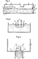
- stirrers 15 there is also provided, in the present invention, at least one pair of stirrers 15, best seen in Fig. 2, which are located just upstream of the entrance 16 to the float canal. Only one pair of stirrers 15 is shown in Fig. 2 for the sake of clarity.
- the individual stirrers 15a and 15b are identical to one another. Each comprises a shaft 17 which, in use, projects substantially vertically downwards into the molten glass. The shafts are driven by suitable drive means, not shown. At its lower, free end each shaft carries a pair of paddles 18a and 18b. The paddles 18a and 18b extend at substantially 90° to the axis of the shaft 18. The two paddles are disposed at an angle of substantially 180° to one another. From Fig.
- the two stirrers are set so that their paddles 18a and 18b are rotationally out of phase by substantially 90° and are rotated at the same speed as one another, which speed lies within the range of 2-20 rpm, but in opposite senses.
- FIG. 3 shows diagramatically the locus of a minute portion of glass under the action of the stirrers.
- the glass portion is caused to move from side to side across a width at least equal to that of the canal whilst in the conditioning zone 8.
- Such movement is an essential feature of the homogenization process; all of the molten glass is attenuated and atypical regions will become interleaved with the remainder of the glass so that the optical distortion produced by them is minimised.
- the glass 6 may either be satisfactorily attenuated before it enters the float canal or such attentuation may be achieved at the canal entrance.
- the aim is the same: to prevent any glass which has not been stirred from by-passing the stirrers 15a, 15b and entering the canal along the side-walls and end walls of the conditioner.
- any glass which follows this path to the canal entrance 16 is collected by the glass which has been subjected to the action of the stirrers 15a, 15b but has not passed into the canal and is returned to the upstream side of the stirrers 15a, 15b.
- the stirrers 15a, 15b stir out any optical defects which might otherwise be formed in the region of the canal entrance 16. Such stirring-out of the defects allow higher surface cooling rates to be used in the conditioner. In existing float glass furnaces where output is limited by the need to avoid these problems, this means that higher glass loads can be produced. Alternatively, in new furnaces, it will be possible to make the conditioning zone 8 considerably smaller in order to obtain glass at the correct temperature to enter the float canal. This, of course, represents a substantial saving in capital costs.
- stirrers 15a, 15b may be water-cooled.
- the conditioning zone can then be operated at a higher temperature. In other words, less cooling air needs to be supplied to the surface of the molten glass 6 in the portion of the conditioning zone 8 upstream of the stirrers 15a, 15b.
- the conditioning zone 8 is operating generally at a higher temperature, the molten glass is, of course, more fluid. This means that the "stagnant" regions of glass adjacent the front end wall of the conditioning zone 8 become smaller and also that the glass in such regions may be flushed out more easily when there is a changeover of the furnace 1 from making one type of glass to another.
- a still further advantage presented by the present invention is that devitrification is far less likely to occur.
Landscapes
- Chemical & Material Sciences (AREA)
- Engineering & Computer Science (AREA)
- Materials Engineering (AREA)
- Organic Chemistry (AREA)
- Glass Melting And Manufacturing (AREA)
- Glass Compositions (AREA)
- Waste-Gas Treatment And Other Accessory Devices For Furnaces (AREA)
- Mixers Of The Rotary Stirring Type (AREA)
Applications Claiming Priority (2)
| Application Number | Priority Date | Filing Date | Title |
|---|---|---|---|
| GB9522123A GB2306467A (en) | 1995-10-28 | 1995-10-28 | Method and apparatus for making glass |
| GB9522123 | 1995-10-28 |
Publications (2)
| Publication Number | Publication Date |
|---|---|
| EP0770582A1 true EP0770582A1 (fr) | 1997-05-02 |
| EP0770582B1 EP0770582B1 (fr) | 1999-01-13 |
Family
ID=10783060
Family Applications (1)
| Application Number | Title | Priority Date | Filing Date |
|---|---|---|---|
| EP96307619A Expired - Lifetime EP0770582B1 (fr) | 1995-10-28 | 1996-10-21 | Procédé et appareil pour l'homogénéisation de verre en fusion par agitation |
Country Status (22)
| Country | Link |
|---|---|
| US (1) | US5827341A (fr) |
| EP (1) | EP0770582B1 (fr) |
| JP (1) | JP4031541B2 (fr) |
| KR (1) | KR100422602B1 (fr) |
| CN (1) | CN1124993C (fr) |
| AR (1) | AR004123A1 (fr) |
| AU (1) | AU714218B2 (fr) |
| BR (1) | BR9605257A (fr) |
| CA (1) | CA2188213C (fr) |
| CZ (1) | CZ288158B6 (fr) |
| DE (1) | DE69601339T2 (fr) |
| ES (1) | ES2128144T3 (fr) |
| GB (1) | GB2306467A (fr) |
| HU (1) | HU216304B (fr) |
| MX (1) | MX9605075A (fr) |
| MY (1) | MY115863A (fr) |
| PL (1) | PL190158B1 (fr) |
| RU (1) | RU2220116C2 (fr) |
| TR (1) | TR199600856A2 (fr) |
| TW (1) | TW372943B (fr) |
| UA (1) | UA48133C2 (fr) |
| ZA (1) | ZA968834B (fr) |
Cited By (2)
| Publication number | Priority date | Publication date | Assignee | Title |
|---|---|---|---|---|
| WO1998005598A1 (fr) * | 1996-08-03 | 1998-02-12 | Pilkington Plc | Installation et procede de production de verre flotte |
| DE10332692A1 (de) * | 2003-07-18 | 2005-02-17 | Schott Ag | Rührvorrichtung zum Behandeln einer Glasschmelze |
Families Citing this family (8)
| Publication number | Priority date | Publication date | Assignee | Title |
|---|---|---|---|---|
| FR2816305B1 (fr) * | 2000-11-07 | 2003-03-14 | Saint Gobain Ct Recherches | Regenerateur de four verrier |
| KR100878605B1 (ko) * | 2001-11-30 | 2009-01-15 | 코닝 인코포레이티드 | 교반에 의한 용융 유리 균질화 방법 및 장치 |
| US7926301B2 (en) * | 2007-08-16 | 2011-04-19 | Corning Incorporated | Method and apparatus for controlling the level of a molten material in a glass manufacturing system |
| US20100199721A1 (en) * | 2008-11-12 | 2010-08-12 | Keisha Chantelle Ann Antoine | Apparatus and method for reducing gaseous inclusions in a glass |
| FR2951156B3 (fr) * | 2009-10-14 | 2011-09-16 | Fives Stein | Perfectionnements apportes au controle de la convection du verre dans un four de verre equipe d'un corset |
| DE102013204451A1 (de) | 2013-03-14 | 2014-09-18 | Schott Ag | Vorrichtung und Verfahren zur Herstellung von Glas, umfassend eineRührvorrichtung zum Rühren einer Glasschmelze |
| RU2555732C1 (ru) * | 2014-04-15 | 2015-07-10 | Открытое Акционерное Общество "Научно-Исследовательский Институт Технического Стекла" | Способ варки стекла |
| CN106380060B (zh) * | 2016-08-29 | 2019-12-10 | 中国建筑材料科学研究总院 | 一种硫系红外玻璃的连续熔制设备 |
Citations (8)
| Publication number | Priority date | Publication date | Assignee | Title |
|---|---|---|---|---|
| US1810911A (en) * | 1926-03-01 | 1931-06-23 | Libbey Owens Ford Glass Co | Glass melting furnace and process for producing molten glass |
| US2063842A (en) * | 1935-01-04 | 1936-12-08 | Hartford Empire Co | Selective apparatus for and method of controlling flow of glass to tank or furnace forehearths |
| US3236618A (en) * | 1963-03-15 | 1966-02-22 | Owens Illinois Glass Co | Glass stirring apparatus |
| US3909227A (en) * | 1973-01-12 | 1975-09-30 | Pilkington Brothers Ltd | Method and apparatus for modifying flow in the refining zone of a glass melting tank |
| US4200448A (en) * | 1977-06-03 | 1980-04-29 | Pilkington Brothers Limited | Glass manufacture |
| EP0047602A1 (fr) * | 1980-09-08 | 1982-03-17 | Libbey-Owens-Ford Co. | Mécanisme d'entrainement d'agitateurs pour four à verre |
| US4744809A (en) * | 1987-01-02 | 1988-05-17 | Ppg Industries, Inc. | Method and apparatus for homogenizing flat glass |
| US5006145A (en) * | 1990-02-26 | 1991-04-09 | Ppg Industries, Inc. | Center biased stirring for improved glass homogenization |
Family Cites Families (13)
| Publication number | Priority date | Publication date | Assignee | Title |
|---|---|---|---|---|
| US1898039A (en) * | 1927-03-04 | 1933-02-21 | William A Morton | Process for producing homogeneous glass in tanks |
| US2124092A (en) * | 1935-03-27 | 1938-07-19 | Ball Brothers Co | Method and apparatus for feeding thermoplastic material |
| US3997315A (en) * | 1974-04-26 | 1976-12-14 | Pilkington Brothers Limited | Glass melting |
| US4082528A (en) * | 1975-01-31 | 1978-04-04 | Pilkington Brothers Limited | Glass melting tank with temperature control and method of melting |
| GB1531742A (en) * | 1975-01-31 | 1978-11-08 | Pilkington Brothers Ltd | Manufacture of glass |
| US4046547A (en) * | 1976-06-10 | 1977-09-06 | Sorg Gmbh & Co. Kg | Glass melting furnace and process for improving the quality of glass |
| US4055408A (en) * | 1976-11-17 | 1977-10-25 | Owens-Illinois, Inc. | Forehearth homogenization method and apparatus |
| FR2478064A1 (fr) * | 1980-03-11 | 1981-09-18 | Saint Gobain Vitrage | Procede et four pour la production de verre fondu |
| FR2604991B1 (fr) * | 1986-10-13 | 1992-11-13 | Saint Gobain Vitrage | Procede et dispositif pour la fusion du verre |
| SU1557110A1 (ru) * | 1987-02-09 | 1990-04-15 | Владимирский политехнический институт | Стекловаренна печь |
| SU1418292A1 (ru) * | 1987-02-20 | 1988-08-23 | Организация П/Я Х-5263 | Печь дл варки боросиликатного стекла |
| US5194081A (en) * | 1989-06-13 | 1993-03-16 | Pilkington Plc | Glass melting process |
| FR2703042B1 (fr) * | 1993-03-23 | 1995-06-09 | Saint Gobain Vitrage Int | Canal d'ecoulement pour le transfert du verre en fusion. |
-
1995
- 1995-10-28 GB GB9522123A patent/GB2306467A/en not_active Withdrawn
-
1996
- 1996-10-18 AU AU70297/96A patent/AU714218B2/en not_active Ceased
- 1996-10-18 CA CA002188213A patent/CA2188213C/fr not_active Expired - Fee Related
- 1996-10-21 ZA ZA968834A patent/ZA968834B/xx unknown
- 1996-10-21 DE DE69601339T patent/DE69601339T2/de not_active Expired - Fee Related
- 1996-10-21 ES ES96307619T patent/ES2128144T3/es not_active Expired - Lifetime
- 1996-10-21 EP EP96307619A patent/EP0770582B1/fr not_active Expired - Lifetime
- 1996-10-22 CZ CZ19963091A patent/CZ288158B6/cs not_active IP Right Cessation
- 1996-10-22 MY MYPI96004379A patent/MY115863A/en unknown
- 1996-10-24 UA UA96104034A patent/UA48133C2/uk unknown
- 1996-10-24 TW TW085113074A patent/TW372943B/zh active
- 1996-10-24 MX MX9605075A patent/MX9605075A/es not_active IP Right Cessation
- 1996-10-25 PL PL96316704A patent/PL190158B1/pl unknown
- 1996-10-25 AR ARP960104930A patent/AR004123A1/es unknown
- 1996-10-25 TR TR96/00856A patent/TR199600856A2/xx unknown
- 1996-10-25 CN CN96122664A patent/CN1124993C/zh not_active Expired - Fee Related
- 1996-10-25 KR KR1019960049882A patent/KR100422602B1/ko not_active Expired - Fee Related
- 1996-10-25 BR BR9605257A patent/BR9605257A/pt not_active IP Right Cessation
- 1996-10-25 US US08/738,053 patent/US5827341A/en not_active Expired - Fee Related
- 1996-10-25 RU RU96121512/63A patent/RU2220116C2/ru not_active IP Right Cessation
- 1996-10-25 HU HU9602958A patent/HU216304B/hu not_active IP Right Cessation
- 1996-10-28 JP JP28517196A patent/JP4031541B2/ja not_active Expired - Fee Related
Patent Citations (8)
| Publication number | Priority date | Publication date | Assignee | Title |
|---|---|---|---|---|
| US1810911A (en) * | 1926-03-01 | 1931-06-23 | Libbey Owens Ford Glass Co | Glass melting furnace and process for producing molten glass |
| US2063842A (en) * | 1935-01-04 | 1936-12-08 | Hartford Empire Co | Selective apparatus for and method of controlling flow of glass to tank or furnace forehearths |
| US3236618A (en) * | 1963-03-15 | 1966-02-22 | Owens Illinois Glass Co | Glass stirring apparatus |
| US3909227A (en) * | 1973-01-12 | 1975-09-30 | Pilkington Brothers Ltd | Method and apparatus for modifying flow in the refining zone of a glass melting tank |
| US4200448A (en) * | 1977-06-03 | 1980-04-29 | Pilkington Brothers Limited | Glass manufacture |
| EP0047602A1 (fr) * | 1980-09-08 | 1982-03-17 | Libbey-Owens-Ford Co. | Mécanisme d'entrainement d'agitateurs pour four à verre |
| US4744809A (en) * | 1987-01-02 | 1988-05-17 | Ppg Industries, Inc. | Method and apparatus for homogenizing flat glass |
| US5006145A (en) * | 1990-02-26 | 1991-04-09 | Ppg Industries, Inc. | Center biased stirring for improved glass homogenization |
Cited By (2)
| Publication number | Priority date | Publication date | Assignee | Title |
|---|---|---|---|---|
| WO1998005598A1 (fr) * | 1996-08-03 | 1998-02-12 | Pilkington Plc | Installation et procede de production de verre flotte |
| DE10332692A1 (de) * | 2003-07-18 | 2005-02-17 | Schott Ag | Rührvorrichtung zum Behandeln einer Glasschmelze |
Also Published As
| Publication number | Publication date |
|---|---|
| UA48133C2 (uk) | 2002-08-15 |
| GB9522123D0 (en) | 1996-01-03 |
| KR970020997A (ko) | 1997-05-28 |
| AU714218B2 (en) | 1999-12-23 |
| ES2128144T3 (es) | 1999-05-01 |
| AR004123A1 (es) | 1998-09-30 |
| TW372943B (en) | 1999-11-01 |
| PL190158B1 (pl) | 2005-11-30 |
| DE69601339D1 (de) | 1999-02-25 |
| HU9602958D0 (en) | 1996-12-30 |
| CZ288158B6 (en) | 2001-05-16 |
| HUP9602958A2 (en) | 1997-05-28 |
| CA2188213C (fr) | 2005-02-22 |
| JPH09165221A (ja) | 1997-06-24 |
| ZA968834B (en) | 1997-04-29 |
| BR9605257A (pt) | 1998-07-21 |
| MY115863A (en) | 2003-09-30 |
| US5827341A (en) | 1998-10-27 |
| TR199600856A2 (tr) | 1997-05-21 |
| AU7029796A (en) | 1997-05-01 |
| JP4031541B2 (ja) | 2008-01-09 |
| CA2188213A1 (fr) | 1997-04-29 |
| PL316704A1 (en) | 1997-05-12 |
| MX9605075A (es) | 1997-04-30 |
| RU2220116C2 (ru) | 2003-12-27 |
| CN1156695A (zh) | 1997-08-13 |
| CZ309196A3 (en) | 1997-07-16 |
| EP0770582B1 (fr) | 1999-01-13 |
| CN1124993C (zh) | 2003-10-22 |
| GB2306467A (en) | 1997-05-07 |
| DE69601339T2 (de) | 1999-06-17 |
| HU216304B (hu) | 1999-06-28 |
| KR100422602B1 (ko) | 2004-06-12 |
| HUP9602958A3 (en) | 1998-08-28 |
Similar Documents
| Publication | Publication Date | Title |
|---|---|---|
| US4046546A (en) | Method and apparatus for refining glass in a melting tank | |
| JP5246568B1 (ja) | ガラスの製造方法、および、攪拌装置 | |
| EP0770582B1 (fr) | Procédé et appareil pour l'homogénéisation de verre en fusion par agitation | |
| KR101306065B1 (ko) | 용융 유리 공급 장치 및 유리 성형품의 제조 방법 | |
| PL178293B1 (pl) | Urządzenie do doprowadzania roztopionego szkła do maszyny do formowania szkła taflowego | |
| US4047918A (en) | Water cooled glass stirrer | |
| US3989497A (en) | Glass melting | |
| JPS638226A (ja) | 溶融ガラスの攪拌装置 | |
| US5006145A (en) | Center biased stirring for improved glass homogenization | |
| US3723084A (en) | Method and apparatus for blending molten glass | |
| US3997315A (en) | Glass melting | |
| CA1086953A (fr) | Fabrication de verre | |
| US4317669A (en) | Glass melting furnace having a submerged weir | |
| US4517000A (en) | Apparatus for producing molten glass | |
| CS216250B2 (en) | Appliance for mixing and homogenization of the frit | |
| JPS5888126A (ja) | 溶融ガラスの撹拌装置 | |
| JPH10338528A (ja) | 高均質ガラスの製造方法 | |
| US4981504A (en) | Process and device for melting glass | |
| JP4793581B2 (ja) | 溶融ガラス供給装置及びガラス成形品の製造方法 | |
| KR800001515B1 (ko) | 용융유리를 혼합 및 균질화하는 전로 균질장치 | |
| JPH10287429A (ja) | 高均質ガラスの製造方法 | |
| CN118652037A (zh) | 一种高铝超薄玻璃均化的方法 | |
| JPS6031774B2 (ja) | 溶融ガラスの調質方法 | |
| MXPA98002597A (en) | Process and apparatus for modifying and homogenizing glass melts | |
| JPS6221721A (ja) | フロ−トガラスの製造装置 |
Legal Events
| Date | Code | Title | Description |
|---|---|---|---|
| PUAI | Public reference made under article 153(3) epc to a published international application that has entered the european phase |
Free format text: ORIGINAL CODE: 0009012 |
|
| AK | Designated contracting states |
Kind code of ref document: A1 Designated state(s): BE DE ES FR GB IT LU NL PT SE |
|
| 17P | Request for examination filed |
Effective date: 19971103 |
|
| 17Q | First examination report despatched |
Effective date: 19971209 |
|
| GRAG | Despatch of communication of intention to grant |
Free format text: ORIGINAL CODE: EPIDOS AGRA |
|
| GRAG | Despatch of communication of intention to grant |
Free format text: ORIGINAL CODE: EPIDOS AGRA |
|
| GRAH | Despatch of communication of intention to grant a patent |
Free format text: ORIGINAL CODE: EPIDOS IGRA |
|
| GRAH | Despatch of communication of intention to grant a patent |
Free format text: ORIGINAL CODE: EPIDOS IGRA |
|
| GRAA | (expected) grant |
Free format text: ORIGINAL CODE: 0009210 |
|
| AK | Designated contracting states |
Kind code of ref document: B1 Designated state(s): BE DE ES FR GB IT LU NL PT SE |
|
| PG25 | Lapsed in a contracting state [announced via postgrant information from national office to epo] |
Ref country code: SE Free format text: THE PATENT HAS BEEN ANNULLED BY A DECISION OF A NATIONAL AUTHORITY Effective date: 19990113 |
|
| REF | Corresponds to: |
Ref document number: 69601339 Country of ref document: DE Date of ref document: 19990225 |
|
| ITF | It: translation for a ep patent filed | ||
| ET | Fr: translation filed | ||
| REG | Reference to a national code |
Ref country code: ES Ref legal event code: FG2A Ref document number: 2128144 Country of ref document: ES Kind code of ref document: T3 |
|
| REG | Reference to a national code |
Ref country code: PT Ref legal event code: SC4A Free format text: AVAILABILITY OF NATIONAL TRANSLATION Effective date: 19990408 |
|
| PLBE | No opposition filed within time limit |
Free format text: ORIGINAL CODE: 0009261 |
|
| STAA | Information on the status of an ep patent application or granted ep patent |
Free format text: STATUS: NO OPPOSITION FILED WITHIN TIME LIMIT |
|
| 26N | No opposition filed | ||
| REG | Reference to a national code |
Ref country code: GB Ref legal event code: IF02 |
|
| PGFP | Annual fee paid to national office [announced via postgrant information from national office to epo] |
Ref country code: NL Payment date: 20061003 Year of fee payment: 11 |
|
| PGFP | Annual fee paid to national office [announced via postgrant information from national office to epo] |
Ref country code: GB Payment date: 20061018 Year of fee payment: 11 |
|
| PGFP | Annual fee paid to national office [announced via postgrant information from national office to epo] |
Ref country code: DE Payment date: 20061019 Year of fee payment: 11 |
|
| PGFP | Annual fee paid to national office [announced via postgrant information from national office to epo] |
Ref country code: PT Payment date: 20061020 Year of fee payment: 11 |
|
| PGFP | Annual fee paid to national office [announced via postgrant information from national office to epo] |
Ref country code: LU Payment date: 20061030 Year of fee payment: 11 |
|
| PGFP | Annual fee paid to national office [announced via postgrant information from national office to epo] |
Ref country code: IT Payment date: 20061031 Year of fee payment: 11 |
|
| PGFP | Annual fee paid to national office [announced via postgrant information from national office to epo] |
Ref country code: ES Payment date: 20061124 Year of fee payment: 11 |
|
| PGFP | Annual fee paid to national office [announced via postgrant information from national office to epo] |
Ref country code: BE Payment date: 20061213 Year of fee payment: 11 |
|
| BERE | Be: lapsed |
Owner name: *PILKINGTON P.L.C. Effective date: 20071031 |
|
| REG | Reference to a national code |
Ref country code: PT Ref legal event code: MM4A Free format text: LAPSE DUE TO NON-PAYMENT OF FEES Effective date: 20080421 |
|
| GBPC | Gb: european patent ceased through non-payment of renewal fee |
Effective date: 20071021 |
|
| NLV4 | Nl: lapsed or anulled due to non-payment of the annual fee |
Effective date: 20080501 |
|
| PG25 | Lapsed in a contracting state [announced via postgrant information from national office to epo] |
Ref country code: DE Free format text: LAPSE BECAUSE OF NON-PAYMENT OF DUE FEES Effective date: 20080501 |
|
| PG25 | Lapsed in a contracting state [announced via postgrant information from national office to epo] |
Ref country code: PT Free format text: LAPSE BECAUSE OF NON-PAYMENT OF DUE FEES Effective date: 20080421 Ref country code: BE Free format text: LAPSE BECAUSE OF NON-PAYMENT OF DUE FEES Effective date: 20071031 |
|
| REG | Reference to a national code |
Ref country code: FR Ref legal event code: ST Effective date: 20080630 |
|
| PG25 | Lapsed in a contracting state [announced via postgrant information from national office to epo] |
Ref country code: NL Free format text: LAPSE BECAUSE OF NON-PAYMENT OF DUE FEES Effective date: 20080501 |
|
| PGFP | Annual fee paid to national office [announced via postgrant information from national office to epo] |
Ref country code: FR Payment date: 20061010 Year of fee payment: 11 |
|
| PG25 | Lapsed in a contracting state [announced via postgrant information from national office to epo] |
Ref country code: GB Free format text: LAPSE BECAUSE OF NON-PAYMENT OF DUE FEES Effective date: 20071021 |
|
| REG | Reference to a national code |
Ref country code: ES Ref legal event code: FD2A Effective date: 20071022 |
|
| PG25 | Lapsed in a contracting state [announced via postgrant information from national office to epo] |
Ref country code: FR Free format text: LAPSE BECAUSE OF NON-PAYMENT OF DUE FEES Effective date: 20071031 Ref country code: ES Free format text: LAPSE BECAUSE OF NON-PAYMENT OF DUE FEES Effective date: 20071022 |
|
| PG25 | Lapsed in a contracting state [announced via postgrant information from national office to epo] |
Ref country code: LU Free format text: LAPSE BECAUSE OF NON-PAYMENT OF DUE FEES Effective date: 20071021 Ref country code: IT Free format text: LAPSE BECAUSE OF NON-PAYMENT OF DUE FEES Effective date: 20071021 |