EP0770802A2 - Dispositif de changement de vitesse pour une boîte de vitesses d'un véhicule automobile avec freinage de l'arbre d'entrée pendant la selection de la marche arrière - Google Patents
Dispositif de changement de vitesse pour une boîte de vitesses d'un véhicule automobile avec freinage de l'arbre d'entrée pendant la selection de la marche arrière Download PDFInfo
- Publication number
- EP0770802A2 EP0770802A2 EP96116619A EP96116619A EP0770802A2 EP 0770802 A2 EP0770802 A2 EP 0770802A2 EP 96116619 A EP96116619 A EP 96116619A EP 96116619 A EP96116619 A EP 96116619A EP 0770802 A2 EP0770802 A2 EP 0770802A2
- Authority
- EP
- European Patent Office
- Prior art keywords
- shift
- reverse gear
- lock
- gear
- finger
- Prior art date
- Legal status (The legal status is an assumption and is not a legal conclusion. Google has not performed a legal analysis and makes no representation as to the accuracy of the status listed.)
- Granted
Links
- 230000005540 biological transmission Effects 0.000 title claims abstract description 9
- 230000007935 neutral effect Effects 0.000 claims abstract description 7
- 238000004519 manufacturing process Methods 0.000 description 1
- 230000001360 synchronised effect Effects 0.000 description 1
Images

Classifications
-
- F—MECHANICAL ENGINEERING; LIGHTING; HEATING; WEAPONS; BLASTING
- F16—ENGINEERING ELEMENTS AND UNITS; GENERAL MEASURES FOR PRODUCING AND MAINTAINING EFFECTIVE FUNCTIONING OF MACHINES OR INSTALLATIONS; THERMAL INSULATION IN GENERAL
- F16H—GEARING
- F16H63/00—Control outputs from the control unit to change-speed- or reversing-gearings for conveying rotary motion or to other devices than the final output mechanism
- F16H63/02—Final output mechanisms therefor; Actuating means for the final output mechanisms
- F16H63/30—Constructional features of the final output mechanisms
- F16H63/302—Final output mechanisms for reversing
-
- F—MECHANICAL ENGINEERING; LIGHTING; HEATING; WEAPONS; BLASTING
- F16—ENGINEERING ELEMENTS AND UNITS; GENERAL MEASURES FOR PRODUCING AND MAINTAINING EFFECTIVE FUNCTIONING OF MACHINES OR INSTALLATIONS; THERMAL INSULATION IN GENERAL
- F16H—GEARING
- F16H63/00—Control outputs from the control unit to change-speed- or reversing-gearings for conveying rotary motion or to other devices than the final output mechanism
- F16H63/02—Final output mechanisms therefor; Actuating means for the final output mechanisms
- F16H63/30—Constructional features of the final output mechanisms
- F16H63/3069—Interrelationship between two or more final output mechanisms
-
- F—MECHANICAL ENGINEERING; LIGHTING; HEATING; WEAPONS; BLASTING
- F16—ENGINEERING ELEMENTS AND UNITS; GENERAL MEASURES FOR PRODUCING AND MAINTAINING EFFECTIVE FUNCTIONING OF MACHINES OR INSTALLATIONS; THERMAL INSULATION IN GENERAL
- F16H—GEARING
- F16H63/00—Control outputs from the control unit to change-speed- or reversing-gearings for conveying rotary motion or to other devices than the final output mechanism
- F16H63/02—Final output mechanisms therefor; Actuating means for the final output mechanisms
- F16H63/30—Constructional features of the final output mechanisms
- F16H63/34—Locking or disabling mechanisms
- F16H63/3408—Locking or disabling mechanisms the locking mechanism being moved by the final actuating mechanism
-
- F—MECHANICAL ENGINEERING; LIGHTING; HEATING; WEAPONS; BLASTING
- F16—ENGINEERING ELEMENTS AND UNITS; GENERAL MEASURES FOR PRODUCING AND MAINTAINING EFFECTIVE FUNCTIONING OF MACHINES OR INSTALLATIONS; THERMAL INSULATION IN GENERAL
- F16H—GEARING
- F16H63/00—Control outputs from the control unit to change-speed- or reversing-gearings for conveying rotary motion or to other devices than the final output mechanism
- F16H63/02—Final output mechanisms therefor; Actuating means for the final output mechanisms
- F16H63/30—Constructional features of the final output mechanisms
- F16H63/38—Detents
-
- Y—GENERAL TAGGING OF NEW TECHNOLOGICAL DEVELOPMENTS; GENERAL TAGGING OF CROSS-SECTIONAL TECHNOLOGIES SPANNING OVER SEVERAL SECTIONS OF THE IPC; TECHNICAL SUBJECTS COVERED BY FORMER USPC CROSS-REFERENCE ART COLLECTIONS [XRACs] AND DIGESTS
- Y10—TECHNICAL SUBJECTS COVERED BY FORMER USPC
- Y10T—TECHNICAL SUBJECTS COVERED BY FORMER US CLASSIFICATION
- Y10T74/00—Machine element or mechanism
- Y10T74/19—Gearing
- Y10T74/19637—Gearing with brake means for gearing
-
- Y—GENERAL TAGGING OF NEW TECHNOLOGICAL DEVELOPMENTS; GENERAL TAGGING OF CROSS-SECTIONAL TECHNOLOGIES SPANNING OVER SEVERAL SECTIONS OF THE IPC; TECHNICAL SUBJECTS COVERED BY FORMER USPC CROSS-REFERENCE ART COLLECTIONS [XRACs] AND DIGESTS
- Y10—TECHNICAL SUBJECTS COVERED BY FORMER USPC
- Y10T—TECHNICAL SUBJECTS COVERED BY FORMER US CLASSIFICATION
- Y10T74/00—Machine element or mechanism
- Y10T74/20—Control lever and linkage systems
- Y10T74/20012—Multiple controlled elements
- Y10T74/20018—Transmission control
- Y10T74/20085—Restriction of shift, gear selection, or gear engagement
- Y10T74/20104—Shift element interlock
Definitions
- the invention relates to a switching device for motor vehicle gearbox with braking of the input shaft when switching on the reverse gear, the type explained in the preamble of patent claim 1.
- a shifting device in which a cam surface is provided on part of the shift lock, which ensures a temporary pressing of the synchronizing device of a forward gear during the preselection movement.
- a switching device in which a bolt arranged on the shift shaft during a preselection movement in the shift gate of the reverse gear acts on a control edge of a shift fork of a forward gear in order to briefly disengage the shift fork from its shift arm via a resilient connection to move and to actuate the synchronizer of a forward gear to brake the input shaft.
- the radially pivotable and axially fixed shift lock remains in its intended position in the transmission housing.
- the known switching devices in the form of the cam surface and in the form of the resilient connections between a shift fork and its shift arm have the disadvantage that they are particularly susceptible to manufacturing tolerances and that the required braking of the input shaft is not achieved in the desired short period of time via the preselection movement and a synchronizing device can be achieved.
- the object of the invention is to provide a switching device for motor vehicle gearboxes with braking of the input shaft when switching on the reverse gear, of the type explained in the preamble of claim 1, with a radially pivotable and essentially axially fixed shift lock in such a way that it is not already during the preselection movement into the shift gate of the reverse gear but only during an initial engagement movement of the reverse gear a temporary actuation of synchronizing devices of forward gears is achieved, whereby the required braking of the input shaft can take place in a desired short period of time by temporarily actuating several synchronizing devices of forward gears.
- this object is achieved by using a switching device for motor vehicle change gearbox Braking the input shaft when switching on the reverse gear, of the type explained in the preamble of claim 1, the features shown in the characterizing part of claim 1 are applied.
- the shift lock is non-positively connected to the shift finger or the shift shaft via a spring / ball catch and is axially movable in the gear housing to a limited extent
- the shift lock is loaded with a number of recesses into its neutral position via a spring by a key plate arranged in a rotationally fixed manner in the gear housing is and is provided on a sleeve part with a number of axially protruding webs that are aligned with the recesses in the key plate when reverse gear is selected
- the shift lock is taken over the spring / ball catch during an initial engagement movement, the webs being in alignment with them Recesses in the key plate can occur.
- a forward gear arranged in the shift gate of the reverse gear for example a 5th gear
- the shift finger has on its sleeve part a protruding in a groove in the sleeve part of the shift lock cam the shift lock can fully fulfill its locking function when engaging 5th gear.
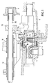
- a gearshift shaft 2 is arranged in a gearbox housing 1 and can actuate all gearshift forks.
- Such so-called single-rod circuits are known per se to the person skilled in the art, but it is pointed out that the invention can be used not only on single-rod circuits but also on switching devices with several switching rods.
- a shift lock 3 which is known per se and which follows a shift finger arranged on the shift shaft 2 during its radially pivoting preselection movement, is arranged on the shift shaft 2 which is radially rotatable and axially displaceable in the transmission housing 1, but is axially fixed here.
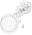
- a key plate 4 is arranged concentrically to the control shaft 2 and is fixed in the transmission housing 1 in a rotationally fixed manner via a bolt / hole connection 5.
- the key plate 4 is provided with a number of recesses 7, which with match with a number of webs 8 which are arranged on an axially extending on the sleeve part of the shift lock 3.
- the recesses 7 in the key plate 4 are aligned with the axially projecting webs 8 of the switching lock 3.
- the shift finger 9 can be arranged as part of the shift shaft 2 or, as shown, in the form of a component fixed on the shift shaft 2.
- a sleeve part of the shift finger 9 and into the shift shaft 2 extends into a bore 10 in which a spring 13 is arranged which loads a ball 11 which cooperates with a ball catch 14 on the inner circumference of the sleeve part of the shift lock 3.
- the shift lock 3 is in this case axially limited movably arranged in the transmission housing 1 and is seen via a spring 15 which is supported on the one hand on the key plate 4 and on the other hand on the sleeve part of the locking plate 3 in FIG 1 held.
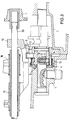
- the braking of the input shaft of the change gearbox is thus initiated by synchronizing the forward gears, here of the 2nd and 4th gears, and the fact that two synchronizing devices are actuated here means that the braking can take place in the desired short period of time.
- the possible travel for braking is determined by the depth of the recesses 7 in the key plate 4, into which the webs 8 of the shift lock 3 penetrate.
- the resistance to axial movement of the selector shaft 2 rises steeply and the non-positive connection in the form of the spring / ball catch 13 / 11-14 is released and the axial one Driving force in the direction of reverse falls sharply.
- the shift lock 3 and the shift forks 16 and 17 interacting therewith for the two forward gears can be pressed back into their neutral starting position by the force of the spring 15.
- the input shaft can rotate freely again.
- the sliding gear of the reverse gear is shifted by the shift finger 9 via the shift arm 23 and the driver 12 and in this case via a shift rod 20, and the sliding gear of the reverse gear can be engaged with low noise.
- the number of axially projecting webs 8 of the shift lock 3 are located next to the recesses 7 in the shift gate or shift level 21 of the 1st and 2nd gear and in the shift level 22 of the 3rd and 4th gear the key plate 4 and the locking plate of the shift lock 3 is therefore held in its neutral position by the abutment of the webs 8 on the key plate 4 axially fixed in the transmission housing 1 and thus the double shift preventing function of the shift lock 3 is reliably maintained.
Landscapes
- Engineering & Computer Science (AREA)
- General Engineering & Computer Science (AREA)
- Mechanical Engineering (AREA)
- Gear-Shifting Mechanisms (AREA)
Applications Claiming Priority (2)
| Application Number | Priority Date | Filing Date | Title |
|---|---|---|---|
| DE19539599A DE19539599C2 (de) | 1995-10-25 | 1995-10-25 | Schalteinrichtung für Kraftfahrzeug-Wechselgetriebe mit Abbremsung der Eingangswelle beim Einschalten des Rückwärtsganges |
| DE19539599 | 1995-10-25 |
Publications (3)
| Publication Number | Publication Date |
|---|---|
| EP0770802A2 true EP0770802A2 (fr) | 1997-05-02 |
| EP0770802A3 EP0770802A3 (fr) | 1999-02-03 |
| EP0770802B1 EP0770802B1 (fr) | 2003-03-12 |
Family
ID=7775660
Family Applications (1)
| Application Number | Title | Priority Date | Filing Date |
|---|---|---|---|
| EP96116619A Expired - Lifetime EP0770802B1 (fr) | 1995-10-25 | 1996-10-17 | Dispositif de changement de vitesse pour une boíte de vitesses d'un véhicule automobile avec freinage de l'arbre d'entrée pendant la selection de la marche arrière |
Country Status (3)
| Country | Link |
|---|---|
| US (1) | US5802917A (fr) |
| EP (1) | EP0770802B1 (fr) |
| DE (2) | DE19539599C2 (fr) |
Cited By (4)
| Publication number | Priority date | Publication date | Assignee | Title |
|---|---|---|---|---|
| DE10109642A1 (de) * | 2001-02-26 | 2002-09-12 | Getrag Getriebe Zahnrad | Schaltvorrichtung zum Einlegen des Rückwärtsganges eines Stirnradgetriebes |
| DE10239916A1 (de) * | 2002-08-30 | 2004-03-04 | Zf Friedrichshafen Ag | Vorrichtung zum Begrenzen des Schaltweges einer Schalteinrichtung |
| WO2011069749A1 (fr) * | 2009-12-09 | 2011-06-16 | Zf Friedrichshafen Ag | Dispositif de changement de vitesse à rail de sélection unique |
| CN109386578A (zh) * | 2017-08-02 | 2019-02-26 | 通用汽车环球科技运作有限责任公司 | 具有倒挡齿轮制动器的变速器 |
Families Citing this family (6)
| Publication number | Priority date | Publication date | Assignee | Title |
|---|---|---|---|---|
| ES2153225T3 (es) | 1998-06-25 | 2001-02-16 | Ford Global Tech Inc | Acoplamiento de arrastre en un varillaje de cambio de marcha. |
| KR100992826B1 (ko) * | 2007-12-14 | 2010-11-08 | 기아자동차주식회사 | 수동변속기용 컨트롤 샤프트 어셈블리 |
| SE533846C2 (sv) * | 2009-06-17 | 2011-02-08 | Scania Cv Ab | Manövreringsanordning för en växellåda |
| DE102010017359A1 (de) | 2010-06-14 | 2011-12-15 | Koki Technik Transmission Systems Gmbh | Betätigungsvorrichtung für ein Schaltgetriebe |
| CN104048040A (zh) * | 2013-03-16 | 2014-09-17 | 江苏普盛动力股份有限公司 | 一种旋外机内置拨档机构 |
| CN115585264B (zh) * | 2022-09-23 | 2024-09-13 | 陕西法士特齿轮有限责任公司 | 一种变速箱挂挡限位机构 |
Family Cites Families (17)
| Publication number | Priority date | Publication date | Assignee | Title |
|---|---|---|---|---|
| US3948363A (en) * | 1972-04-19 | 1976-04-06 | The B. F. Goodrich Company | Friction member assembly |
| JPS57137750A (en) * | 1981-02-20 | 1982-08-25 | Nissan Motor Co Ltd | Operator for change gear |
| US4430904A (en) * | 1981-08-24 | 1984-02-14 | Borg-Warner Corporation | Multiple speed ratio transmission with anti-clash brake |
| DE3147782C2 (de) * | 1981-12-03 | 1984-08-30 | Ford-Werke AG, 5000 Köln | Schalteinrichtung für den Rückwärtsgang mit Abbremsung der Eingangswelle eines Kraftfahrzeugwechselgetriebes in Vorgelegebauweise |
| JPS5975964U (ja) * | 1982-11-15 | 1984-05-23 | トヨタ自動車株式会社 | 手動変速機におけるリバ−スギヤ鳴り防止装置 |
| JPS6091844U (ja) * | 1983-11-29 | 1985-06-22 | トヨタ自動車株式会社 | 手動変速機の操作機構 |
| US4821590A (en) * | 1987-06-18 | 1989-04-18 | Tury Edward L | Electronic control system for control of electronic electric shift apparatus for manual transmission |
| US4817468A (en) * | 1987-06-18 | 1989-04-04 | Ap Aero, Inc | Electric shift apparatus for manual transmission |
| FR2618510B1 (fr) * | 1987-07-20 | 1989-12-08 | Peugeot | Dispositif de freinage de pignons d'une boite de vitesses de vehicule automobile |
| US5036721A (en) * | 1990-09-28 | 1991-08-06 | General Motors Corporation | Shift control mechanism for a manual transmission |
| US5136897A (en) * | 1991-05-09 | 1992-08-11 | Eaton Corporation | Smooth upshift control method/system |
| US5274553A (en) * | 1991-05-09 | 1993-12-28 | Eaton Corporation | Torque converter slip rate based skip power downshift control strategy |
| US5099711A (en) * | 1991-05-09 | 1992-03-31 | Eaton Corporation | Tooth butt/buzz control method/system |
| JP2588978Y2 (ja) * | 1991-11-06 | 1999-01-20 | 本田技研工業株式会社 | 車両用手動変速機 |
| JP3163874B2 (ja) * | 1993-09-30 | 2001-05-08 | スズキ株式会社 | 変速機のリバースギヤ鳴り防止装置 |
| US5454764A (en) * | 1993-12-03 | 1995-10-03 | General Motors Corporation | Manual transmission control |
| JP3463369B2 (ja) * | 1994-08-31 | 2003-11-05 | スズキ株式会社 | リバースギヤ鳴き防止装置 |
-
1995
- 1995-10-25 DE DE19539599A patent/DE19539599C2/de not_active Expired - Fee Related
-
1996
- 1996-10-17 EP EP96116619A patent/EP0770802B1/fr not_active Expired - Lifetime
- 1996-10-17 DE DE59610214T patent/DE59610214D1/de not_active Expired - Fee Related
- 1996-10-17 US US08/733,651 patent/US5802917A/en not_active Expired - Fee Related
Cited By (4)
| Publication number | Priority date | Publication date | Assignee | Title |
|---|---|---|---|---|
| DE10109642A1 (de) * | 2001-02-26 | 2002-09-12 | Getrag Getriebe Zahnrad | Schaltvorrichtung zum Einlegen des Rückwärtsganges eines Stirnradgetriebes |
| DE10239916A1 (de) * | 2002-08-30 | 2004-03-04 | Zf Friedrichshafen Ag | Vorrichtung zum Begrenzen des Schaltweges einer Schalteinrichtung |
| WO2011069749A1 (fr) * | 2009-12-09 | 2011-06-16 | Zf Friedrichshafen Ag | Dispositif de changement de vitesse à rail de sélection unique |
| CN109386578A (zh) * | 2017-08-02 | 2019-02-26 | 通用汽车环球科技运作有限责任公司 | 具有倒挡齿轮制动器的变速器 |
Also Published As
| Publication number | Publication date |
|---|---|
| DE19539599C2 (de) | 1997-08-14 |
| DE19539599A1 (de) | 1997-04-30 |
| DE59610214D1 (de) | 2003-04-17 |
| EP0770802A3 (fr) | 1999-02-03 |
| US5802917A (en) | 1998-09-08 |
| EP0770802B1 (fr) | 2003-03-12 |
Similar Documents
| Publication | Publication Date | Title |
|---|---|---|
| DE102008028619A1 (de) | Schaltvorrichtung für ein Getriebe | |
| EP2580497B1 (fr) | Dispositif d'actionnement pour une boîte de vitesses | |
| DE2633730B2 (de) | Mechanische Schalteinrichtung für ein Zahnräderwechselgetriebe | |
| DE3150885C2 (fr) | ||
| DE3850929T2 (de) | Wählhebelsperre für Automatikgetriebe. | |
| DE4029456C2 (de) | Schalteinrichtung für ein Wechselgetriebe | |
| DE19901056A1 (de) | Schaltvorrichtung mit Einwellenschaltung | |
| DE10203633A1 (de) | Schaltvorrichtung eines Getriebes | |
| EP0770802B1 (fr) | Dispositif de changement de vitesse pour une boíte de vitesses d'un véhicule automobile avec freinage de l'arbre d'entrée pendant la selection de la marche arrière | |
| DE3011131C2 (fr) | ||
| EP0412279A2 (fr) | Dispositif de changement de vitesses pour la boîte de vitesses d'une voiture | |
| DE19857713A1 (de) | Betätigungsvorrichtung | |
| EP1304513B1 (fr) | Boíte de vitesses avec dispositif de verouillage des rapports individuels | |
| DE3228790A1 (de) | Mechanismus fuer ein manuell schaltbares getriebe | |
| DE2341199A1 (de) | Schalteinrichtung fuer mechanische wechselgetriebe von kraftfahrzeugen | |
| DE10045266C2 (de) | Schaltvorrichtung zum Betätigen eines mehrstufigen Schaltgetriebes | |
| DE19901055A1 (de) | Einwellenschalteinrichtung | |
| DE102004060232A1 (de) | Elektrische Schalteinrichtung für ein automatisiertes Getriebe | |
| DE102018206392B4 (de) | Schalteinrichtung zur durchführung von gangwechseln in einem fahrzeuggetriebe | |
| DE112005001381B4 (de) | Gangschaltsystem | |
| DE2510154A1 (de) | Schalteinrichtung fuer wechselgetriebe von kraftfahrzeugen | |
| EP1281895B1 (fr) | Mécanisme de verrouillage pour commande de changement de vitesse | |
| DE69716869T2 (de) | Sicherheitseinrichtung für mechanisches schaltgetriebe | |
| DE60006457T2 (de) | Getriebe kompakter Bauart mit Schwenkfüssen zur Betätigung von Schaltgabeln | |
| DE3424793C2 (de) | Schaltvorrichtung für ein Zahnräderwechselgetriebe eines Kraftfahrzeuges |
Legal Events
| Date | Code | Title | Description |
|---|---|---|---|
| PUAI | Public reference made under article 153(3) epc to a published international application that has entered the european phase |
Free format text: ORIGINAL CODE: 0009012 |
|
| AK | Designated contracting states |
Kind code of ref document: A2 Designated state(s): DE FR GB |
|
| RAP1 | Party data changed (applicant data changed or rights of an application transferred) |
Owner name: FORD GLOBAL TECHNOLOGIES, INC. |
|
| PUAL | Search report despatched |
Free format text: ORIGINAL CODE: 0009013 |
|
| AK | Designated contracting states |
Kind code of ref document: A3 Designated state(s): DE FR GB |
|
| 17P | Request for examination filed |
Effective date: 19990803 |
|
| GRAH | Despatch of communication of intention to grant a patent |
Free format text: ORIGINAL CODE: EPIDOS IGRA |
|
| GRAH | Despatch of communication of intention to grant a patent |
Free format text: ORIGINAL CODE: EPIDOS IGRA |
|
| GRAA | (expected) grant |
Free format text: ORIGINAL CODE: 0009210 |
|
| AK | Designated contracting states |
Designated state(s): DE FR GB |
|
| REG | Reference to a national code |
Ref country code: GB Ref legal event code: FG4D Free format text: NOT ENGLISH |
|
| REF | Corresponds to: |
Ref document number: 59610214 Country of ref document: DE Date of ref document: 20030417 Kind code of ref document: P |
|
| GBT | Gb: translation of ep patent filed (gb section 77(6)(a)/1977) |
Effective date: 20030725 |
|
| ET | Fr: translation filed | ||
| PLBE | No opposition filed within time limit |
Free format text: ORIGINAL CODE: 0009261 |
|
| STAA | Information on the status of an ep patent application or granted ep patent |
Free format text: STATUS: NO OPPOSITION FILED WITHIN TIME LIMIT |
|
| 26N | No opposition filed |
Effective date: 20031215 |
|
| PGFP | Annual fee paid to national office [announced via postgrant information from national office to epo] |
Ref country code: GB Payment date: 20050914 Year of fee payment: 10 |
|
| PGFP | Annual fee paid to national office [announced via postgrant information from national office to epo] |
Ref country code: FR Payment date: 20051006 Year of fee payment: 10 |
|
| PGFP | Annual fee paid to national office [announced via postgrant information from national office to epo] |
Ref country code: DE Payment date: 20051031 Year of fee payment: 10 |
|
| PG25 | Lapsed in a contracting state [announced via postgrant information from national office to epo] |
Ref country code: DE Free format text: LAPSE BECAUSE OF NON-PAYMENT OF DUE FEES Effective date: 20070501 |
|
| GBPC | Gb: european patent ceased through non-payment of renewal fee |
Effective date: 20061017 |
|
| REG | Reference to a national code |
Ref country code: FR Ref legal event code: ST Effective date: 20070629 |
|
| PG25 | Lapsed in a contracting state [announced via postgrant information from national office to epo] |
Ref country code: GB Free format text: LAPSE BECAUSE OF NON-PAYMENT OF DUE FEES Effective date: 20061017 |
|
| PG25 | Lapsed in a contracting state [announced via postgrant information from national office to epo] |
Ref country code: FR Free format text: LAPSE BECAUSE OF NON-PAYMENT OF DUE FEES Effective date: 20061031 |