EP0770835A2 - Collecteur solaire pour le chauffage d'eau - Google Patents
Collecteur solaire pour le chauffage d'eau Download PDFInfo
- Publication number
- EP0770835A2 EP0770835A2 EP96117278A EP96117278A EP0770835A2 EP 0770835 A2 EP0770835 A2 EP 0770835A2 EP 96117278 A EP96117278 A EP 96117278A EP 96117278 A EP96117278 A EP 96117278A EP 0770835 A2 EP0770835 A2 EP 0770835A2
- Authority
- EP
- European Patent Office
- Prior art keywords
- solar collector
- water
- collector according
- heat
- container
- Prior art date
- Legal status (The legal status is an assumption and is not a legal conclusion. Google has not performed a legal analysis and makes no representation as to the accuracy of the status listed.)
- Withdrawn
Links
Images

Classifications
-
- F—MECHANICAL ENGINEERING; LIGHTING; HEATING; WEAPONS; BLASTING
- F24—HEATING; RANGES; VENTILATING
- F24S—SOLAR HEAT COLLECTORS; SOLAR HEAT SYSTEMS
- F24S60/00—Arrangements for storing heat collected by solar heat collectors
- F24S60/30—Arrangements for storing heat collected by solar heat collectors storing heat in liquids
-
- F—MECHANICAL ENGINEERING; LIGHTING; HEATING; WEAPONS; BLASTING
- F24—HEATING; RANGES; VENTILATING
- F24S—SOLAR HEAT COLLECTORS; SOLAR HEAT SYSTEMS
- F24S80/00—Details, accessories or component parts of solar heat collectors not provided for in groups F24S10/00-F24S70/00
- F24S80/50—Elements for transmitting incoming solar rays and preventing outgoing heat radiation; Transparent coverings
- F24S80/56—Elements for transmitting incoming solar rays and preventing outgoing heat radiation; Transparent coverings characterised by means for preventing heat loss
-
- Y—GENERAL TAGGING OF NEW TECHNOLOGICAL DEVELOPMENTS; GENERAL TAGGING OF CROSS-SECTIONAL TECHNOLOGIES SPANNING OVER SEVERAL SECTIONS OF THE IPC; TECHNICAL SUBJECTS COVERED BY FORMER USPC CROSS-REFERENCE ART COLLECTIONS [XRACs] AND DIGESTS
- Y02—TECHNOLOGIES OR APPLICATIONS FOR MITIGATION OR ADAPTATION AGAINST CLIMATE CHANGE
- Y02E—REDUCTION OF GREENHOUSE GAS [GHG] EMISSIONS, RELATED TO ENERGY GENERATION, TRANSMISSION OR DISTRIBUTION
- Y02E10/00—Energy generation through renewable energy sources
- Y02E10/40—Solar thermal energy, e.g. solar towers
Definitions
- the invention relates to a solar collector with the features of the preamble of claim 1.
- Hot water is generated in a tubular storage absorber by solar radiation. This hot water is protected from cooling over night or over a bad weather day by surrounding the entire system with a heat-insulating wall.
- This heat-insulating wall consisting of a glass pane with a transparent, heat-insulating medium underneath and a PU rigid foam insulation in the lower area - forms a self-contained but relatively large insulated room.
- the insulating wall is not vapor-tight (especially in the area of the glass pane), so that depending on the temperature and the humidity of the air in the container or the environment, condensation occurs in the container and mists up the inside of the glass pane. This leads to a reduction in the efficiency of the collector. This problem is particularly evident in coastal regions with high humidity and corresponding temperature fluctuations.
- the invention is therefore based on the object of creating a solar collector in which the condensation is largely prevented while at the same time being simple and inexpensive, or in the case of condensation the efficiency reduction is only relatively slight.
- the underside of the irradiation area pointing in the direction of the interior of the container is delimited by an absorber plate.
- This has the advantage that the volume for the medium to be heated, e.g. Water, does not have to be vapor-tight, since condensation on the inside of the absorber plate - if this should be possible at all due to the complete filling of the interior of the container with the medium to be heated - is irrelevant.
- the volume of the irradiation area can also be separated from the volume of the rest of the insulating jacket in a vapor-tight manner by the absorber plate.
- a transparent heat-insulating medium is introduced in the space between the transparent plate of the irradiation area and the absorber plate in order to improve the insulating effect of this jacket area.
- the dissolution of condensed water on the inside of the transparent plate can be accelerated if the volume of the irradiation area has openings for the circulation of air, for example on the side walls of the volume determined by the transparent plate and the absorber plate. This Openings can be closed by a vapor-permeable membrane, eg felt.
- Arranging the absorber plate directly below the volume of the irradiation area can result in the disadvantage of ice formation within the volume for the medium to be heated, in particular if a heat-insulating transparent material in the Irradiation area is dispensed with.
- Such extremely inexpensive versions can also be used in regions with large temperature fluctuations. However, there is a risk of the collector being destroyed as a result of the volume expansion of the heat-storing medium.
- the volume of the container for the heat-storing medium and the material of the container wall and / or the dimensions thereof are therefore selected such that the volume expansion in the event of freezing leads to an exclusively elastic deformation of the container wall.
- the container can have edges in its wall, which allow the container to expand in volume when the volume expands due to an elastic bending stress.
- the container wall can also have curvatures that allow the container volume to be increased when subjected to bending stress.
- a part of the volume of the container can also be separated by a boundary wall and filled with a freeze-proof liquid.
- the volume expansion of the freezing medium can then be compensated for by the sufficiently deformable boundary wall be, a corresponding volume of the freeze-proof liquid is pressed into the overflow vessel.
- the special design of the water container to ensure freeze protection is of course independent of the special design of the thermal insulation and can also be used separately for any other collectors, but has the advantages mentioned in connection with the invention.
- the condensation is prevented by creating an essentially closed space (I) with a small volume in the region of the absorber plate (3) for the thermal insulation of the water container (4). Only a little water can condense from the air in this small volume. If the narrow end faces with a vapor-permeable membrane (7), for example with Felted, closed, so possibly over night on the transparent plate (1), eg insulating glass, condensed water when exposed to sunlight by heating the black coated absorber plate (3) as steam very quickly to the outside. The sun can then reach the absorber plate (3) unhindered by condensate.
- a hygroscopic agent can be added, which stores the condensate and only releases it when there is sufficient solar radiation so that it can escape as steam.
- the self-contained space (II) serves to insulate the water tank (4) in the area of the steel sheet (5) arranged below and has the size that is usual insulation (6), e.g. by means of fibrous materials.
- Rooms (I) and (II) are separated from each other in a vapor-tight manner. Condensation in room (II) can therefore have no negative influence.
- the absorber plate (3) can have a greater material thickness than the remaining part of the water container (4).
- the steel volume of the absorber plate (3) then acts as a heat store in addition to the water contained in the water tank (4).
- the volume of the water container (4) is minimized.
- the solar collector then shrinks to a water heater.
- the hot water obtained in this way can then be pumped to a separate, heat-insulated storage tank by means of a circulation pump.
- the collector on the roof has only a low weight, which is important for movable collectors that are to be adapted to the respective sun positions.
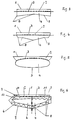
- the steel sheet (5) which can otherwise be designed as desired, has a special shape. This is clearly outlined in FIGS. 1 to 6. That e.g. Sheet metal (5) that is folded sideways and in the middle is given its own stability by the fold (8).
- the water tank (4) can thus be manufactured very inexpensively.
- Another effect is decisive: In mountainous areas, the water in the water tank (4) can freeze when it is very cold and cloudy for days.
- the planes obtained by the edge (8) of the sheet (5) can bulge to a certain extent due to the pressure of the ice and the edge angles can easily open further without large material stresses.
- the folded circumference of the steel sheet (5) in the examples according to FIGS. 1 to 4 and 6 or the special shape according to FIG. 5 creates a water volume that is smaller than it would automatically be under high pressure.
- a water tank (4) constructed in this way is always frost-proof. Since the stresses that occur in every freezing situation remain in the elastic range, the steel sheet (5) subsequently returns to its original shape or the steel sheet (5) can be easily returned to its original position by external forces. Such forces can e.g. Use steel springs that are arranged on an outer frame in such a way that they automatically tension when freezing.
- a special embodiment of the solar collector is shown in cross section in FIG. 6.
- the left and right half of this cross-section shows another possible variant as an example.
- This embodiment includes an additional liquid container which is arranged separately from the water container (4) (11) for taking up a liquid that is both freeze-proof and has high heat storage properties.
- This liquid container (11) is delimited at the top by the absorber plate (3) and at the bottom by the steel sheet (12). Below this is the water tank (4), which is delimited by the steel sheets (5) and (12).
- the steel sheet (12) has the function of a heat exchanger.
- the surface of the steel sheet (12) can be increased by the steel sheet (12) having a corrugated, serrated or ribbed cross section.
- Such cross sections can also be deformed very easily in the elastic region by ice pressure, so that the solar collector cannot be damaged in the event of a freeze.
- a pressure valve is set according to the water pressure in the water tank (4), and if you take precautions that the steel sheet (12) does not deform when the water tank (4) and liquid tank (11) are filled for the first time, the steel sheet (12) always remains in the normal case free of bending and tension.
- the entire elastic deformation potential remains reserved for freezing.
- volume (4) can be provided anywhere in the interior of the container, e.g. also between the top of the lower inner wall of the container and the medium to be heated then arranged above it.
Landscapes
- Engineering & Computer Science (AREA)
- Chemical & Material Sciences (AREA)
- Life Sciences & Earth Sciences (AREA)
- Sustainable Development (AREA)
- Sustainable Energy (AREA)
- Thermal Sciences (AREA)
- Physics & Mathematics (AREA)
- Combustion & Propulsion (AREA)
- Mechanical Engineering (AREA)
- General Engineering & Computer Science (AREA)
- Thermotherapy And Cooling Therapy Devices (AREA)
- Heat Treatment Of Water, Waste Water Or Sewage (AREA)
- Heat-Pump Type And Storage Water Heaters (AREA)
Applications Claiming Priority (4)
| Application Number | Priority Date | Filing Date | Title |
|---|---|---|---|
| PT10178895 | 1995-10-26 | ||
| PT101788A PT101788A (pt) | 1995-10-26 | 1995-10-26 | Colector solar para a obtencao de agua quente com energia solar |
| DE19610117 | 1996-03-14 | ||
| DE19610117 | 1996-03-14 |
Publications (2)
| Publication Number | Publication Date |
|---|---|
| EP0770835A2 true EP0770835A2 (fr) | 1997-05-02 |
| EP0770835A3 EP0770835A3 (fr) | 1998-07-29 |
Family
ID=26023817
Family Applications (1)
| Application Number | Title | Priority Date | Filing Date |
|---|---|---|---|
| EP96117278A Withdrawn EP0770835A3 (fr) | 1995-10-26 | 1996-10-28 | Collecteur solaire pour le chauffage d'eau |
Country Status (1)
| Country | Link |
|---|---|
| EP (1) | EP0770835A3 (fr) |
Family Cites Families (6)
| Publication number | Priority date | Publication date | Assignee | Title |
|---|---|---|---|---|
| US3995613A (en) * | 1975-02-18 | 1976-12-07 | Ppg Industries, Inc. | Solar heat collector unit |
| US4127104A (en) * | 1977-05-09 | 1978-11-28 | Solar Works, Inc. | Solar heater for water and the like |
| US4350145A (en) * | 1981-01-30 | 1982-09-21 | Societa Italiana Brevetti | Solar collector for heating purposes |
| JPS5949449A (ja) * | 1982-09-16 | 1984-03-22 | Aruna Koki Kk | 建物壁材用の蓄熱パネル |
| US4557251A (en) * | 1984-02-13 | 1985-12-10 | Helmut Burkhardt | Solar water boiling device |
| DE3706196A1 (de) * | 1987-02-26 | 1988-09-29 | Fraunhofer Ges Forschung | Warmwasserbereiter in form eines solarkollektors |
-
1996
- 1996-10-28 EP EP96117278A patent/EP0770835A3/fr not_active Withdrawn
Non-Patent Citations (1)
| Title |
|---|
| None |
Also Published As
| Publication number | Publication date |
|---|---|
| EP0770835A3 (fr) | 1998-07-29 |
Similar Documents
| Publication | Publication Date | Title |
|---|---|---|
| DE2330700C2 (de) | Wandelelement zur Speicherung von Wärme durch Aufnahme von Sonnenenergie und/oder zur Abstrahlung von Überschußwärme im infraroten Bereich des Spektrums | |
| DE2721467C2 (de) | Vorfabriziertes Fassadenelement mit einem auf der Innenseite angeordneten Heizkörper | |
| DE2654143A1 (de) | Rohrfoermiger sonnenenergiekollektor | |
| DE2601976A1 (de) | Solar-plattensammler | |
| EP0351546B1 (fr) | Collecteur solaire pour produire des températures élevées | |
| DE2925151C2 (de) | Sonnenkollektor | |
| EP0061697B1 (fr) | Elément de stockage du froid, avec éléments de montage et aillettes réglant l'air | |
| DE3121351A1 (de) | Abstandhalter fuer eine vakuum-isoliereinrichtung | |
| DE69506710T2 (de) | Sonnenkollektor | |
| DE3027996A1 (de) | Sonnenkollektor | |
| DE202009017830U1 (de) | Solar-Flachkollektor | |
| EP0846245B1 (fr) | Collecteur de chaleur solaire | |
| DE3390005C2 (fr) | ||
| DE3048499A1 (de) | Einrichtung zur umsetzung von sonnenenergie in waerme | |
| DE4239286A1 (de) | Sonnenkollektor zur Wassererwärmung | |
| DE3225588A1 (de) | Waermetauscher | |
| DE3226461A1 (de) | Warmwasserspeicherbehaelter | |
| DE2608302A1 (de) | Verfahren und vorrichtung zum auffangen von sonnenenergie | |
| EP0770835A2 (fr) | Collecteur solaire pour le chauffage d'eau | |
| DE10039111B4 (de) | Solarabsorber | |
| DE2151467A1 (de) | Isolation zur Verringerung der Waermeuebertragung zwischen einer Flaeche und einer Fluessigkeit | |
| DE3015061A1 (de) | Sonnenkollektor mit ueberhitzungsschutz | |
| EP0294319B1 (fr) | Dispositif pour produire la chaleur et le froid à l'aide d'un collecteur solaire | |
| DE10018079C2 (de) | Abdeckung für Spargelfelder | |
| AT375171B (de) | Waermeumsetzer, insbesondere sonnenenergieabsorber |
Legal Events
| Date | Code | Title | Description |
|---|---|---|---|
| PUAI | Public reference made under article 153(3) epc to a published international application that has entered the european phase |
Free format text: ORIGINAL CODE: 0009012 |
|
| AK | Designated contracting states |
Kind code of ref document: A2 Designated state(s): AT DE ES IT PT |
|
| PUAL | Search report despatched |
Free format text: ORIGINAL CODE: 0009013 |
|
| AK | Designated contracting states |
Kind code of ref document: A3 Designated state(s): AT DE ES IT PT |
|
| STAA | Information on the status of an ep patent application or granted ep patent |
Free format text: STATUS: THE APPLICATION IS DEEMED TO BE WITHDRAWN |
|
| 18D | Application deemed to be withdrawn |
Effective date: 19990130 |