EP0771241B1 - Automatisiertes verfahren zur kontrolle beim stumpfnachweissen und zur fehlerdiagnose - Google Patents
Automatisiertes verfahren zur kontrolle beim stumpfnachweissen und zur fehlerdiagnose Download PDFInfo
- Publication number
- EP0771241B1 EP0771241B1 EP95915664A EP95915664A EP0771241B1 EP 0771241 B1 EP0771241 B1 EP 0771241B1 EP 95915664 A EP95915664 A EP 95915664A EP 95915664 A EP95915664 A EP 95915664A EP 0771241 B1 EP0771241 B1 EP 0771241B1
- Authority
- EP
- European Patent Office
- Prior art keywords
- emat
- weld
- electrical signal
- welding apparatus
- data acquisition
- Prior art date
- Legal status (The legal status is an assumption and is not a legal conclusion. Google has not performed a legal analysis and makes no representation as to the accuracy of the status listed.)
- Expired - Lifetime
Links
Images

Classifications
-
- G—PHYSICS
- G01—MEASURING; TESTING
- G01N—INVESTIGATING OR ANALYSING MATERIALS BY DETERMINING THEIR CHEMICAL OR PHYSICAL PROPERTIES
- G01N29/00—Investigating or analysing materials by the use of ultrasonic, sonic or infrasonic waves; Visualisation of the interior of objects by transmitting ultrasonic or sonic waves through the object
- G01N29/22—Details, e.g. general constructional or apparatus details
- G01N29/24—Probes
- G01N29/2412—Probes using the magnetostrictive properties of the material to be examined, e.g. electromagnetic acoustic transducers [EMAT]
-
- B—PERFORMING OPERATIONS; TRANSPORTING
- B23—MACHINE TOOLS; METAL-WORKING NOT OTHERWISE PROVIDED FOR
- B23K—SOLDERING OR UNSOLDERING; WELDING; CLADDING OR PLATING BY SOLDERING OR WELDING; CUTTING BY APPLYING HEAT LOCALLY, e.g. FLAME CUTTING; WORKING BY LASER BEAM
- B23K11/00—Resistance welding; Severing by resistance heating
- B23K11/36—Auxiliary equipment
-
- B—PERFORMING OPERATIONS; TRANSPORTING
- B23—MACHINE TOOLS; METAL-WORKING NOT OTHERWISE PROVIDED FOR
- B23K—SOLDERING OR UNSOLDERING; WELDING; CLADDING OR PLATING BY SOLDERING OR WELDING; CUTTING BY APPLYING HEAT LOCALLY, e.g. FLAME CUTTING; WORKING BY LASER BEAM
- B23K31/00—Processes relevant to this subclass, specially adapted for particular articles or purposes, but not covered by any single one of main groups B23K1/00 - B23K28/00
- B23K31/12—Processes relevant to this subclass, specially adapted for particular articles or purposes, but not covered by any single one of main groups B23K1/00 - B23K28/00 relating to investigating the properties, e.g. the weldability, of materials
-
- G—PHYSICS
- G01—MEASURING; TESTING
- G01N—INVESTIGATING OR ANALYSING MATERIALS BY DETERMINING THEIR CHEMICAL OR PHYSICAL PROPERTIES
- G01N2291/00—Indexing codes associated with group G01N29/00
- G01N2291/04—Wave modes and trajectories
- G01N2291/042—Wave modes
- G01N2291/0422—Shear waves, transverse waves, horizontally polarised waves
-
- G—PHYSICS
- G01—MEASURING; TESTING
- G01N—INVESTIGATING OR ANALYSING MATERIALS BY DETERMINING THEIR CHEMICAL OR PHYSICAL PROPERTIES
- G01N2291/00—Indexing codes associated with group G01N29/00
- G01N2291/26—Scanned objects
- G01N2291/267—Welds
- G01N2291/2675—Seam, butt welding
Definitions
- the present invention relates in general to a method for weld inspection and defect analysis, and more specifically to an automated method for non-destructive inspection and evaluation of a butt weld through the use of ultrasonic waves.
- An inspection device that uses ultrasonic waves to non-destructively test the welds shortly after they have been made.
- the device employs Electromagnetic Acoustic Transducers (EMAT) which are arranged to transmit and receive what are known to be SH shear waves.
- EMAT Electromagnetic Acoustic Transducers
- the SH shear waves are launched by a transmitter meander coil EMAT, and the waves travel through the sheet metal to the weld where they are reflected back through the sheet metal and are received by a separate receiver meander coil EMAT located near the transmitter.
- the reflected wave produces an electrical signal in the receiver coil, which is monitored while both the transmitter coil and the receiver coil are scanned close to the surface of the sheet metal, parallel to the weld line, and over the full width of the sheet metal. During the scanning, the amplitude of the signal produced in the receiver coil is measured and used to indicate the quality of the weld.
- the known device is retrofitted into a flash butt welding machine on a production line, and a motorized transport apparatus into which the transmitter and receiver coils are mounted is used to carry out each weld scan.
- operation of the known device requires full-time control by a human operator, who, through the manipulation of push buttons, moves and positions the transport apparatus with the transmitter and receiver coils onto and across the sheet metal surface subsequent to the making of each weld by the welding machine.
- Results of the test i.e., the measured amplitude of the receiver coil signal, are recorded on a device such as a strip chart recorder and are monitored and interpreted by the human operator.
- the present invention has among its principal novel features automatic positioning of a transport apparatus containing EMAT transmitter and receiver coils in proximity of a just-completed weld; scanning the weld; receiving the electrical signal produced in the receiver coil by the reflected SH shear wave; recording and monitoring the electrical signal; analyzing the electrical signal relative to certain predetermined weld quality control limits which have been preprogrammed into the inspection system; signaling the presence of a defect in the weld; and communicating electronically with the welding apparatus to reperform the just-completed weld and/or to alter the way in which subsequent welds are made so as to avoid repetition of the observed defect. Also included among the novel features of the present invention is automatic receiving, recording and monitoring of selected information pertaining to the welding apparatus and to the making of each weld by the welding apparatus. Such information is received, recorded and monitored concurrent with the making of each weld
- the present invention is performed in part with the aid of a computer control unit which is instrumental in providing automated control of the transport apparatus which will be situated downstream of the welding apparatus.
- the computer control unit has an electrical interface with the controller of the welding apparatus, as well as, with the transport apparatus and a data acquisition device.
- the interface to the controller of the welding apparatus is used to coordinate the sequence by which the inspection process is actuated.
- signals are received by the computer control unit from the welding apparatus. These signals are used generally to coordinate the non-destructive weld test with a terminal step in the welding process, known as the flash removal step, where excess weld metal is trimmed from the just-completed weld.
- the signals received from the computer control unit during the flash removal step are used to initiate and implement the positioning of the transport apparatus in proximity of the weld and thereafter commence scanning of the weld by the EMAT transmitter and receiver coils.
- An advantage gained by coordinating the weld test and the flash removal step is minimization of the amount of time added by the test to the overall cycle time, i.e., the time that elapses between commencement of the welding operation and completion of the non-destructive test.
- the use of the computer control unit and its integration with the welder controller eliminates the need for a human to observe the welding operation and to determine when to begin positioning the transport apparatus near the weld.
- the transport apparatus has affixed to it an edge detection sensor which is used to help position the EMAT coils onto the sheet metal surface at one of the sheet's edges before the weld scanning step commences.
- the edge detection sensor which is in electrical communication with the computer control unit, produces an electrical signal when the leading edge of the sheet metal is sensed. The signal is transmitted to the computer control unit which positions the EMAT coils and makes them ready for the scan.
- the transport apparatus is moved mechanically across the width of the sheet metal.
- the ultrasonic SH shear waves produced by the EMAT transmitter coil travel through the sheet metal where they are reflected back through the sheet metal and are received by the EMAT receiver coil.
- the reflected wave produces an electrical signal in the receiver coil and that signal is transmitted to the computer control unit by way of the electrical interface between the transport apparatus and the computer control unit.
- the signal which is in essence raw weld inspection data, is then relayed to a data acquisition unit via the electrical interface between the computer control unit and the data acquisition unit.
- the edge detection sensor used to help position the EMAT coils before commencement of the weld scan is also employed to ascertain the end of the scanning step. Movement of the transport apparatus across the width of the sheet metal eventually causes the edge detection sensor to sense the trailing edge of the sheet metal. Upon detecting the trailing edge, the edge detection sensor produces an electrical signal which is transmitted to the computer control unit which in turn activates the removal of the EMAT coils from the surface of the sheet metal and the positioning of the transport apparatus at a safe location off the welding process line during the period where no weld inspection is required.
- a data acquisition unit is employed with the present invention.
- the data acquisition unit is utilized for automatically: (1) receiving, recording, monitoring and displaying preselected welding apparatus and welding process data as such data are generated upon the making of each weld; (2) receiving, recording, monitoring, displaying and analyzing the weld inspection data produced during the weld scanning step; (3) signaling the presence and location of a weld defect contemporaneously with the weld scanning step; and (4) communicating electronically with the welding apparatus to reperform a just-completed weld and/or to alter the way in which subsequent welds are made.
- the data acquisition unit is generally comprised of a 486-based IBM/PC compatible computer, a computer keyboard, a video display monitor, computer software capable of processing the data transmitted to the data acquisition unit, and electronic interconnections to the computer control unit and to the welding apparatus.
- Welding apparatus and welding process data are transmitted to the data acquisition unit by way of an electronic interconnection between the welding apparatus and the data acquisition unit.
- Transmitted data may include: welding process currents and voltages; weld apparatus platen movements; hydraulic pressures and temperatures; load cam to load plate measurement; welder events, such as die position, status and cycle time; upset cylinder differential pressure; upset force; servo amplifier signals; die level and hydraulic reservoir fluid level.
- Predetermined weld quality control limits are also stored on the data acquisition unit.
- the weld quality control limits are employed in evaluating the weld inspection data received from each weld scan.
- an alarm indication is displayed to the welding apparatus operator if a signal which is outside of stored weld quality control limits is received from the EMAT receiver coil.
- any one or more of the welding apparatus and/or welding process parameters corresponding to the welding apparatus and welding process data transmitted to the data acquisition unit may be automatically adjusted through computer control.
- Non-destructive test data indicating a defective weld may in turn result in an automatic re-weld operation.
- the data acquisition unit is also used to collect and archive empirical data that may be used for later off-production line post-analysis, historical tracking and process monitoring.
- a flat, plate-like, metal calibration station is also provided for practising the present invention.
- the calibration station may be employed either on or off the sheet metal processing line to check and adjust the EMAT transmitter and receiver coils and other weld inspection system electronics. On-line use of the calibration station may be made without adversely impacting production operations.
- a typical sheet metal production and treatment line on which the present invention may be utilized is comprised of a rolling mill, a plurality of roughing stands, a plurality of finishing stands, a first shearing apparatus, a welding apparatus, a temper mill, a pickling apparatus, a water rinse apparatus, a drying apparatus, a second shearing apparatus, a side splitter apparatus and a tandem cold mill.
- a long flat sheet of metal produced by the rolling mill will be wound into a coil after passing through the finishing stands.
- the coil will then be transported to the first shearing apparatus located at another section of the factory and the end of that coil will be joined at the welding apparatus to the trailing end of another earlier transported coil which, for the most part, has already passed through a number of processing and treatment stations downstream of the welding apparatus.
- the location where the non-destructive weld test is made lies between the welding apparatus and the temper mill.
- Fig. 1 provides a cross sectional visualization of end portions (20) of two sheet metal coils, which are connected by a butt weld (22) made by the welding apparatus. Also shown in Fig. 1, are an EMAT transmitter coil (24) and an EMAT receiver coil (26), both of which are positioned just downstream of the butt weld (22) on a surface of the end portion (20) of one of the sheet metal coils.
- EMAT transmitter coil (24) produces an ultrasonic SH shear wave (28) which travels through end portion (20) toward butt weld (22) where a fraction of the SH shear wave (28) passes through the butt weld (22) and a fraction of the wave passes back through the end portion (20) and toward the EMAT receiver coil (26) as a reflected wave (29).
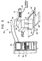
- Fig. 2 illustrates the fundamental components of the weld inspection system used with the present invention.
- the weld inspection system has a computer control unit (31) which is in electrical communication with the welding apparatus, an L-shaped transport apparatus (32) and a data acquisition unit (33).
- a first cable (34) provides the electrical connection between the computer control unit (31) and the welding apparatus.
- a second cable (35) electrically connects the computer control unit (31) to the transport apparatus (32), and a third cable (36) links the computer control unit (31) to the data acquisition unit (33).
- the transport apparatus (32) which is positioned just down stream of the butt weld (22), has housed within one of its ends the EMAT transmitter coil (24) and the EMAT receiver coil (26).
- An edge detection sensor (37) is affixed to the transport apparatus in proximity of the EMAT transmitter coil (24).
- the edge detection sensor (37) which is in electrical communication with the computer control unit (31), is used to position the EMAT coils (24) and (26) at an edge of the end portion (20) of one of the sheet metal coils and to detect when the weld scan is complete.
- the data acquisition unit (33) includes a computer (39), a computer keyboard (40), a video display monitor (41) and a cable (42) having a connector (43), both of which provide for electrical connection of the data acquisition unit (33) to the welding apparatus.
Landscapes
- Physics & Mathematics (AREA)
- Mechanical Engineering (AREA)
- Engineering & Computer Science (AREA)
- Chemical & Material Sciences (AREA)
- Pathology (AREA)
- Analytical Chemistry (AREA)
- Biochemistry (AREA)
- General Health & Medical Sciences (AREA)
- General Physics & Mathematics (AREA)
- Immunology (AREA)
- Life Sciences & Earth Sciences (AREA)
- Health & Medical Sciences (AREA)
- Electromagnetism (AREA)
- Investigating Or Analyzing Materials By The Use Of Ultrasonic Waves (AREA)
- Paper (AREA)
- Control Of Electric Motors In General (AREA)
- Pressure Welding/Diffusion-Bonding (AREA)
- Investigating Materials By The Use Of Optical Means Adapted For Particular Applications (AREA)
Claims (13)
- Automatisiertes Verfahren für die zerstörungsfreie Untersuchung und Auswertung einer stumpfgeschweißten Stoßnaht (22), welche verwendet wird, um zwei Bleche mit ihren beiden Enden (20) aneinander zu verbinden, wobei das Verfahren die Schritte aufweist:elektronisches Übermitteln von Information, welche sich auf die Schweißvorrichtung und das Verfahren bezieht, durch welche die Stoßnaht durch die Schweißvorrichtung hergestellt worden ist, von einer Schweißvorrichtung an eine Datenerfassungseinheit (33) eines zerstörungsfreien Schweißuntersuchungssystems,Speichern in der Datenerfassungseinheit (33) der von der Schweißvorrichtung zu der Datenerfassungseinheit (33) übermittelten Information,Positionieren einer Transportvorrichtung (32) des zerstörungsfreien Schweißuntersuchungssystems in der Nähe der Stoßnaht, wobei das System einen ersten (24) und eine zweiten (26) elektromagnetischen, akustischen Wandler (EMAT) hat, welcher an der Transporteinrichtung (32) angebracht und in dieser aufgenommen ist,Abtasten der Stoßnaht (22) mit der Transportvorrichtung (32), während der erste EMAT (24) eine Ultraschall-SH-Scherwelle erzeugt, welche durch einen Endabschnitt eines ersten Metallbleches in Richtung einer Schweißverbindung gesendet wird, welche den Endabschnitt der ersten Blechspule mit einem Endabschnitt einer zweiten Blechspule (20) verbindet, und während der zweite EMAT (26) eine Ultraschall-SH-Scherwelle empfängt, die von der Stoßnaht (22) reflektiert wird und die in dem zweiten EMAT ein elektrisches Signal hervorruft,Senden des in dem zweiten EMAT erzeugten elektrischen Signals an die Datenerfassungseinheit (33)Aufzeichnen in der Datenerfassungseinheit (33) des in dem zweiten EMAT erzeugten elektrischen Signales (26),Analysieren in der Datenerfassungseinheit des in dem zweiten EMAT erzeugten elektrischen SignalsAnzeigen des Vorhandenseins eines Fehlers in der Schweißnaht, wenn eine Analyse des elektrischen Signals, welches in dem zweiten EMAT (26) erzeugt wurde, einen Fehler anzeigt,elektronische Kommunikation mit der Schweißvorrichtung, um die Stoßnaht (22) zu überarbeiten und/oder um das Verfahren zum Herstellen einer oder mehrerer nachfolgender Stoßnähte zu verändern, wenn die Analyse des in dem zweiten EMAT (26) erzeugten elektrischen Signales einen Fehler anzeigt.
- Verfahren nach Anspruch 1, wobei eine Computersteuereinheit (31) des zerstörungsfrei-. en Schweißuntersuchungssystems, welches in elektrischer Verbindung mit der Schweißvorrichtung steht, die Transporteinheit (32) und die Datenaufnahmeeinheit (33) die Positionierung der Transportvorrichtung (32) in der Nähe der Schweißnaht (22) auslöst und durchführt und daraufhin das Abtasten der geschweißten Stoßnaht (22) durch die Transportvorrichtung (32) ausführt.
- Verfahren nach Anspruch 2, wobei ein elektrisches Signal, welches von der Schweißvorrichtung an die Computersteuerungseinheit (31) ausgesendet wird, nach der Fertigstellung der Stoßnaht (22) verwendet wird, um die Positionierung der Transportvorrichtung (32) auszulösen.
- Verfahren nach Anspruch 3, wobei ein Kantenerfassungssensor (37), der an der Transporteinheit (32) angebracht ist und der in elektrischer Verbindung mit der Computersteuereinheit (31) steht, ein erstes elektrisches Signal erzeugt, welches von der Computersteuereinheit (31) verwendet wird, um den ersten EMAT (24) und den zweiten EMAT (26) auf der Oberfläche des Endabschnittes der ersten Blechspule und in der Nähe der Stoßnaht (22) zu positionieren, bevor das Abtasten stattfindet.
- Verfahren nach Anspruch 4, wobei der Kantenerfassungssensor (37) ein zweites elektrisches Signal erzeugt, welches von der Computersteuereinheit (31) verwendet wird, um den ersten EMAT (24) und den zweiten EMAT (26) mit der Oberfläche des Endbereiches der ersten Blechspule außer Eingriff zu bringen, und die Transportvorrichtung (32) in eine Position weg von der Schweißvorrichtung zu transportieren, nachdem das Abtasten der Stoßnaht (22) beendet worden ist.
- Verfahren nach Anspruch 5, wobei das erste elektrische Signal von dem Kantenerfassungssensor (37) erzeugt wird, wenn der Kantenerfassungssensor (37) in die Nähe einer führenden (vorderen) Kante des Endabschnittes der ersten Blechspule bewegt wird und diese erfaßt, und daß das zweite elektrische Signal von dem Kantenerfassungssensor (37) erzeugt wird, wenn der Kantenerfassungssensor sich einer nachlaufenden (hinteren) Kante des Endabschnittes der ersten Blechspule (20) nähert und diese erfaßt.
- Verfahren nach Anspruch 6, wobei die Computersteuereinheit (31) verwendet wird, um das von dem zweiten EMAT (26) während des Abtastens der Schweißnaht (22) erzeugte elektrische Signal zu empfangen und das Signal auf die Datenerfassungseinheit (33) zu schalten.
- Verfahren nach Anspruch 7, wobei die Datenerfassungseinheit (33) aus einer Computertastatur (40), einem Videoanzeigemonitor (41) und einem Computer (39), wie z.B. einem 486-IBM/PC besteht, welcher eine Software hat, die in der Lage ist, das elektrische Signal, weiches in dem zweiten EMAT (26) erzeugt wird und die Information, die von der Schweißvorrichtung zu der Datenerfassungseinheit gesendet wird, zu empfangen, aufzuzeichnen, zu überwachen und zu analysieren.
- Verfahren nach Anspruch 8, wobei der Computer (39) das in dem zweiten EMAT (26) erzeugte elektrische Signal im Verhältnis zu einer Vielzahl von Grenzwerten einer Schweißqualitätskontrolle analysiert, die vorher in dem Computer (39) programmiert worden sind.
- Verfahren nach Anspruch 9, wobei der Computer (39) verwendet wird, um einem Benutzer der Schweißvorrichtung die Anwesenheit und Position eines Fehlers in der Schweißnaht (22) anzuzeigen, wenn die Analyse des von dem zweiten EMAT (26) erzeugten elektrischen Signales zeigt, daß ein Grenzwert der Qualitätskontrolle der Schweißnaht nicht eingehalten worden ist.
- Verfahren nach Anspruch 10, wobei dann, wenn die Analyse des durch den zweiten EMAT (26) erzeugten elektrischen Signales zeigt daß ein Grenzwert der Schweißqualitätskontrolle nicht eingehalten worden ist, der Computer (39) auch verwendet wird, um die an die Datengewinnungseinheit (33) von der Schweißvorrichtung gesendete Information zu analysieren, und um dadurch zu bestimmen, ob und in welchem Maße Einstellungen der Schweißvorrichtung erforderlich sind und ob die Stoßschweißung erneut hergestellt werden sollte.
- Verfahren nach Anspruch 11, wobei die Computersteuereinheit (31) verwendet wird, um elektronisch mit der Schweißvorrichtung in Verbindung zu treten und um spezielle Einstellungen zu übertragen, die durch den Computer (39) bestimmt worden sind, und auch Anweisungen, ob die Stoßschweißnaht (22) erneuert werden sollte.
- Verfahren nach Anspruch 12, wobei eine Kalibrierstation (38) verwendet wird, um entweder die erste EMAT-Spule (24) oder die zweite EMAT-Spule (26) oder beide zu überprüfen und einzustellen.
Applications Claiming Priority (3)
| Application Number | Priority Date | Filing Date | Title |
|---|---|---|---|
| US276286 | 1994-07-18 | ||
| US08/276,286 US5474225A (en) | 1994-07-18 | 1994-07-18 | Automated method for butt weld inspection and defect diagnosis |
| PCT/US1995/004542 WO1996002349A1 (en) | 1994-07-18 | 1995-04-12 | Automated method for butt weld inspection and defect diagnosis |
Publications (3)
| Publication Number | Publication Date |
|---|---|
| EP0771241A1 EP0771241A1 (de) | 1997-05-07 |
| EP0771241A4 EP0771241A4 (de) | 1998-02-25 |
| EP0771241B1 true EP0771241B1 (de) | 2000-10-18 |
Family
ID=23056029
Family Applications (1)
| Application Number | Title | Priority Date | Filing Date |
|---|---|---|---|
| EP95915664A Expired - Lifetime EP0771241B1 (de) | 1994-07-18 | 1995-04-12 | Automatisiertes verfahren zur kontrolle beim stumpfnachweissen und zur fehlerdiagnose |
Country Status (8)
| Country | Link |
|---|---|
| US (1) | US5474225A (de) |
| EP (1) | EP0771241B1 (de) |
| AT (1) | ATE197007T1 (de) |
| AU (1) | AU2247195A (de) |
| DE (1) | DE69519167T2 (de) |
| DK (1) | DK0771241T3 (de) |
| ES (1) | ES2151058T3 (de) |
| WO (1) | WO1996002349A1 (de) |
Families Citing this family (39)
| Publication number | Priority date | Publication date | Assignee | Title |
|---|---|---|---|---|
| AU2241695A (en) * | 1994-07-18 | 1996-02-16 | Babcock & Wilcox Co., The | Sensor transport system for flash butt welder |
| US5763786A (en) * | 1996-09-18 | 1998-06-09 | The Babcock & Wilcox Company | Automated mill roll inspection system |
| US5866820A (en) * | 1996-09-20 | 1999-02-02 | Camplin; Kenneth R. | Coil volumetric and surface defect detection system |
| US6122967A (en) * | 1998-06-18 | 2000-09-26 | The United States Of America As Represented By The United States Department Of Energy | Free motion scanning system |
| US6297467B1 (en) | 1999-04-01 | 2001-10-02 | Daimlerchrysler Corporation | Transducer built into an electrode |
| US6116090A (en) * | 1999-04-30 | 2000-09-12 | Daimlerchrysler Corporation | Multieyed acoustical microscopic lens system |
| US6546803B1 (en) | 1999-12-23 | 2003-04-15 | Daimlerchrysler Corporation | Ultrasonic array transducer |
| FR2806801B1 (fr) * | 2000-03-23 | 2002-05-03 | Snecma | Procede d'evaluation de resilience d'un assemblage soude et appareil d'analyse correspondant mesurant des vitesses d'ondes ultrasonores superficielles |
| US6625515B2 (en) * | 2000-12-21 | 2003-09-23 | Dofasco Inc. | Roll defect management process |
| EA007258B1 (ru) * | 2002-07-17 | 2006-08-25 | Шелл Интернэшнл Рисерч Маатсхаппий Б.В. | Контроль сварных соединений с использованием электромагнитно-акустических преобразователей (эмап) |
| DK1531959T3 (da) | 2002-07-17 | 2008-06-16 | Shell Int Research | Fremgangsmåde ti sammenföjning af udvidelige rör |
| US7282663B2 (en) * | 2002-07-29 | 2007-10-16 | Shell Oil Company | Forge welding process |
| US7774917B2 (en) * | 2003-07-17 | 2010-08-17 | Tubefuse Applications B.V. | Forge welding tubulars |
| US20050169346A1 (en) * | 2004-01-29 | 2005-08-04 | Trw Automotive U.S. Llc | Method for monitoring quality of a transmissive laser weld |
| WO2007116629A1 (ja) * | 2006-04-11 | 2007-10-18 | Kawasaki Jukogyo Kabushiki Kaisha | 摩擦撹拌接合物の検査方法および検査装置 |
| US9104195B2 (en) | 2006-12-20 | 2015-08-11 | Lincoln Global, Inc. | Welding job sequencer |
| US10994358B2 (en) | 2006-12-20 | 2021-05-04 | Lincoln Global, Inc. | System and method for creating or modifying a welding sequence based on non-real world weld data |
| US9937577B2 (en) | 2006-12-20 | 2018-04-10 | Lincoln Global, Inc. | System for a welding sequencer |
| RU2350943C1 (ru) * | 2007-07-10 | 2009-03-27 | Закрытое акционерное общество научно-исследовательский институт интроскопии Московского научно-производственного объединения "СПЕКТР" (ЗАО НИИИН МНПО "СПЕКТР") | Магнитная система электромагнитно-акустического преобразователя |
| US20220317095A1 (en) * | 2021-01-14 | 2022-10-06 | JANA Corporation | Method, device and system for non-destructive evaluation of polyethylene pipe joints using ultrasound and machine learning |
| CN101398411B (zh) * | 2008-11-07 | 2012-04-25 | 哈尔滨工业大学 | 钢轨踏面缺陷快速扫查方法及其装置 |
| US9052273B2 (en) * | 2010-04-23 | 2015-06-09 | Primetals Technologies France SAS | Method and installation for ultrasound inspection of butt-welding of two transverse ends of two metal strips |
| AU2012364909B2 (en) | 2011-02-15 | 2016-11-24 | Hemosonics, Llc | Characterization of blood hemostasis and oxygen transport parameters |
| US9027404B2 (en) | 2012-05-17 | 2015-05-12 | Honeywell International Inc. | Ultrasonic non-destructive evaluation methods for friction-welded blisks |
| US10040141B2 (en) | 2013-05-23 | 2018-08-07 | Crc-Evans Pipeline International, Inc. | Laser controlled internal welding machine for a pipeline |
| US10480862B2 (en) | 2013-05-23 | 2019-11-19 | Crc-Evans Pipeline International, Inc. | Systems and methods for use in welding pipe segments of a pipeline |
| WO2016033568A1 (en) | 2014-08-29 | 2016-03-03 | Crc-Evans Pipeline International Inc. | Method and system for welding |
| US9821415B2 (en) | 2014-03-28 | 2017-11-21 | Crc-Evans Pipeline International, Inc. | Internal pipeline cooler |
| US10695876B2 (en) | 2013-05-23 | 2020-06-30 | Crc-Evans Pipeline International, Inc. | Self-powered welding systems and methods |
| US11767934B2 (en) | 2013-05-23 | 2023-09-26 | Crc-Evans Pipeline International, Inc. | Internally welded pipes |
| US10589371B2 (en) | 2013-05-23 | 2020-03-17 | Crc-Evans Pipeline International, Inc. | Rotating welding system and methods |
| CN105643133A (zh) * | 2014-09-28 | 2016-06-08 | 中国海洋石油总公司 | 管道环焊缝人工缺陷的制作方法 |
| US9726647B2 (en) | 2015-03-17 | 2017-08-08 | Hemosonics, Llc | Determining mechanical properties via ultrasound-induced resonance |
| US11458571B2 (en) | 2016-07-01 | 2022-10-04 | Crc-Evans Pipeline International, Inc. | Systems and methods for use in welding pipe segments of a pipeline |
| GB2552486B (en) | 2016-07-25 | 2020-07-08 | Hs Marston Aerospace Ltd | Method and system for joint inspection |
| FI3815884T3 (en) * | 2019-10-30 | 2024-09-11 | Fischer G Rohrleitungssysteme Ag | METHOD FOR CHECKING THE WELD |
| CN114660177B (zh) * | 2022-03-11 | 2025-09-16 | 中车唐山机车车辆有限公司 | 焊缝检测方法、装置及设备 |
| CN114799452A (zh) * | 2022-03-14 | 2022-07-29 | 中国船舶重工集团公司第七二五研究所 | 一种钛合金大厚板电子束焊接工艺优化方法 |
| CN118032939B (zh) * | 2024-04-15 | 2024-07-30 | 葫芦岛北检科技有限公司 | 一种采用声磁组合技术检测奥氏体焊缝的方法 |
Family Cites Families (10)
| Publication number | Priority date | Publication date | Assignee | Title |
|---|---|---|---|---|
| GB1147089A (en) * | 1966-11-22 | 1969-04-02 | Nat Res Dev | Ultrasonic inspection system for materials |
| US3850028A (en) * | 1972-11-16 | 1974-11-26 | Rockwell International Corp | Method for ultrasonic inspection |
| US4058002A (en) * | 1976-12-23 | 1977-11-15 | The United States Of America As Represented By The Secretary Of The Air Force | Dispersive electromagnetic surface acoustic wave transducer |
| US4289030A (en) * | 1979-08-01 | 1981-09-15 | Rockwell International Corporation | Nondestructive testing utilizing horizontally polarized shear waves |
| US4295214A (en) * | 1979-08-23 | 1981-10-13 | Rockwell International Corporation | Ultrasonic shear wave transducer |
| US4307616A (en) * | 1979-12-26 | 1981-12-29 | Rockwell International Corporation | Signal processing technique for ultrasonic inspection |
| US4596917A (en) * | 1984-01-16 | 1986-06-24 | General Electric Company | Resistance spot welder process monitor |
| US5154081A (en) * | 1989-07-21 | 1992-10-13 | Iowa State University Research Foundation, Inc. | Means and method for ultrasonic measurement of material properties |
| US5085082A (en) * | 1990-10-24 | 1992-02-04 | The Babcock & Wilcox Company | Apparatus and method of discriminating flaw depths in the inspection of tubular products |
| US5359898A (en) * | 1991-06-04 | 1994-11-01 | The Babcock & Wilcox Company | Hydrogen damage confirmation with EMATs |
-
1994
- 1994-07-18 US US08/276,286 patent/US5474225A/en not_active Expired - Fee Related
-
1995
- 1995-04-12 DK DK95915664T patent/DK0771241T3/da active
- 1995-04-12 EP EP95915664A patent/EP0771241B1/de not_active Expired - Lifetime
- 1995-04-12 DE DE69519167T patent/DE69519167T2/de not_active Expired - Fee Related
- 1995-04-12 AU AU22471/95A patent/AU2247195A/en not_active Abandoned
- 1995-04-12 AT AT95915664T patent/ATE197007T1/de not_active IP Right Cessation
- 1995-04-12 WO PCT/US1995/004542 patent/WO1996002349A1/en not_active Ceased
- 1995-04-12 ES ES95915664T patent/ES2151058T3/es not_active Expired - Lifetime
Also Published As
| Publication number | Publication date |
|---|---|
| AU2247195A (en) | 1996-02-16 |
| ES2151058T3 (es) | 2000-12-16 |
| ATE197007T1 (de) | 2000-11-15 |
| EP0771241A4 (de) | 1998-02-25 |
| US5474225A (en) | 1995-12-12 |
| EP0771241A1 (de) | 1997-05-07 |
| DK0771241T3 (da) | 2000-11-13 |
| DE69519167T2 (de) | 2001-05-17 |
| WO1996002349A1 (en) | 1996-02-01 |
| DE69519167D1 (de) | 2000-11-23 |
Similar Documents
| Publication | Publication Date | Title |
|---|---|---|
| US5474225A (en) | Automated method for butt weld inspection and defect diagnosis | |
| US5439157A (en) | Automated butt weld inspection system | |
| US5777229A (en) | Sensor transport system for combination flash butt welder | |
| US5763786A (en) | Automated mill roll inspection system | |
| US5537876A (en) | Apparatus and method for nondestructive evaluation of butt welds | |
| US4419562A (en) | Nondestructive real-time method for monitoring the quality of a weld | |
| KR101995418B1 (ko) | 용접부의 비파괴 검사 자동화 시스템 | |
| US20050132809A1 (en) | Methods for ultrasonic inspection of spot and seam resistance welds in metallic sheets and a spot weld examination probe system (SWEPS) | |
| US4480475A (en) | Real-time ultrasonic weld inspection method | |
| CN102869987A (zh) | 两个金属带材的两个横向端的对接焊缝的超声波检测方法及设备 | |
| US20190321909A1 (en) | Welding process and welding apparatus | |
| KR20190081614A (ko) | 초음파를 이용한 용접부의 용접품질 검사 시스템 | |
| CN103323458A (zh) | 一种焊缝检测装置、焊缝检测系统及焊缝检测方法 | |
| JPH06265529A (ja) | スポット溶接部の評価方法及び装置 | |
| US12175649B2 (en) | Characterization and classification of spot welds by ultrasonic diagnostic techniques | |
| EP2239564B1 (de) | Schweiss-inspektionsverfahren und -inspektionsvorrichtung | |
| US8302479B2 (en) | Method of evaluation using ultrasonic waves | |
| CN1063848C (zh) | 热钢板在线自动化电磁超声探伤系统 | |
| JP2002071649A (ja) | 溶接監視方法 | |
| JPH01197069A (ja) | 自己診断機能付自動溶接装置 | |
| KR102377160B1 (ko) | 실시간 용접부 검출 기능을 갖는 용접 장치 및 실시간 용접부 검출 방법 | |
| Latham et al. | EMAT weld inspection and weld machine diagnostic system for continuous coil processing lines | |
| JPH05223788A (ja) | 薄板の溶接部の健全性診断方法 | |
| JP2598398B2 (ja) | ストリツプ溶接強度測定装置 | |
| Acebes et al. | Development of an automated ultrasonic inspection device for quality control of spot welds |
Legal Events
| Date | Code | Title | Description |
|---|---|---|---|
| PUAI | Public reference made under article 153(3) epc to a published international application that has entered the european phase |
Free format text: ORIGINAL CODE: 0009012 |
|
| 17P | Request for examination filed |
Effective date: 19960702 |
|
| AK | Designated contracting states |
Kind code of ref document: A1 Designated state(s): AT BE CH DE DK ES FR GB GR IE IT LI LU MC NL PT SE |
|
| A4 | Supplementary search report drawn up and despatched |
Effective date: 19980109 |
|
| AK | Designated contracting states |
Kind code of ref document: A4 Designated state(s): AT BE CH DE DK ES FR GB GR IE IT LI LU MC NL PT SE |
|
| RAP1 | Party data changed (applicant data changed or rights of an application transferred) |
Owner name: BWX TECHNOLOGIES, INC. |
|
| GRAG | Despatch of communication of intention to grant |
Free format text: ORIGINAL CODE: EPIDOS AGRA |
|
| 17Q | First examination report despatched |
Effective date: 19991222 |
|
| GRAG | Despatch of communication of intention to grant |
Free format text: ORIGINAL CODE: EPIDOS AGRA |
|
| GRAH | Despatch of communication of intention to grant a patent |
Free format text: ORIGINAL CODE: EPIDOS IGRA |
|
| RAP1 | Party data changed (applicant data changed or rights of an application transferred) |
Owner name: MAST AUTOMATION, INC. |
|
| GRAH | Despatch of communication of intention to grant a patent |
Free format text: ORIGINAL CODE: EPIDOS IGRA |
|
| GRAA | (expected) grant |
Free format text: ORIGINAL CODE: 0009210 |
|
| ITF | It: translation for a ep patent filed | ||
| AK | Designated contracting states |
Kind code of ref document: B1 Designated state(s): AT BE CH DE DK ES FR GB GR IE IT LI LU MC NL PT SE |
|
| REF | Corresponds to: |
Ref document number: 197007 Country of ref document: AT Date of ref document: 20001115 Kind code of ref document: T |
|
| REG | Reference to a national code |
Ref country code: CH Ref legal event code: NV Representative=s name: MICHELI & CIE INGENIEURS-CONSEILS Ref country code: CH Ref legal event code: EP |
|
| REG | Reference to a national code |
Ref country code: DK Ref legal event code: T3 |
|
| REG | Reference to a national code |
Ref country code: IE Ref legal event code: FG4D |
|
| ET | Fr: translation filed | ||
| REF | Corresponds to: |
Ref document number: 69519167 Country of ref document: DE Date of ref document: 20001123 |
|
| REG | Reference to a national code |
Ref country code: ES Ref legal event code: FG2A Ref document number: 2151058 Country of ref document: ES Kind code of ref document: T3 |
|
| PG25 | Lapsed in a contracting state [announced via postgrant information from national office to epo] |
Ref country code: PT Free format text: LAPSE BECAUSE OF FAILURE TO SUBMIT A TRANSLATION OF THE DESCRIPTION OR TO PAY THE FEE WITHIN THE PRESCRIBED TIME-LIMIT Effective date: 20010118 |
|
| PG25 | Lapsed in a contracting state [announced via postgrant information from national office to epo] |
Ref country code: GR Free format text: LAPSE BECAUSE OF FAILURE TO SUBMIT A TRANSLATION OF THE DESCRIPTION OR TO PAY THE FEE WITHIN THE PRESCRIBED TIME-LIMIT Effective date: 20010119 |
|
| PG25 | Lapsed in a contracting state [announced via postgrant information from national office to epo] |
Ref country code: LU Free format text: LAPSE BECAUSE OF NON-PAYMENT OF DUE FEES Effective date: 20010412 Ref country code: IE Free format text: LAPSE BECAUSE OF NON-PAYMENT OF DUE FEES Effective date: 20010412 |
|
| PG25 | Lapsed in a contracting state [announced via postgrant information from national office to epo] |
Ref country code: MC Free format text: LAPSE BECAUSE OF NON-PAYMENT OF DUE FEES Effective date: 20010430 |
|
| PLBE | No opposition filed within time limit |
Free format text: ORIGINAL CODE: 0009261 |
|
| 26N | No opposition filed | ||
| REG | Reference to a national code |
Ref country code: GB Ref legal event code: IF02 |
|
| REG | Reference to a national code |
Ref country code: IE Ref legal event code: MM4A |
|
| PGFP | Annual fee paid to national office [announced via postgrant information from national office to epo] |
Ref country code: FR Payment date: 20020319 Year of fee payment: 8 |
|
| PGFP | Annual fee paid to national office [announced via postgrant information from national office to epo] |
Ref country code: SE Payment date: 20020320 Year of fee payment: 8 Ref country code: AT Payment date: 20020320 Year of fee payment: 8 |
|
| PGFP | Annual fee paid to national office [announced via postgrant information from national office to epo] |
Ref country code: NL Payment date: 20020321 Year of fee payment: 8 Ref country code: DK Payment date: 20020321 Year of fee payment: 8 |
|
| PGFP | Annual fee paid to national office [announced via postgrant information from national office to epo] |
Ref country code: CH Payment date: 20020322 Year of fee payment: 8 |
|
| PGFP | Annual fee paid to national office [announced via postgrant information from national office to epo] |
Ref country code: GB Payment date: 20020403 Year of fee payment: 8 |
|
| PGFP | Annual fee paid to national office [announced via postgrant information from national office to epo] |
Ref country code: BE Payment date: 20020416 Year of fee payment: 8 |
|
| PGFP | Annual fee paid to national office [announced via postgrant information from national office to epo] |
Ref country code: DE Payment date: 20020418 Year of fee payment: 8 |
|
| PGFP | Annual fee paid to national office [announced via postgrant information from national office to epo] |
Ref country code: ES Payment date: 20020509 Year of fee payment: 8 |
|
| PG25 | Lapsed in a contracting state [announced via postgrant information from national office to epo] |
Ref country code: GB Free format text: LAPSE BECAUSE OF NON-PAYMENT OF DUE FEES Effective date: 20030412 Ref country code: AT Free format text: LAPSE BECAUSE OF NON-PAYMENT OF DUE FEES Effective date: 20030412 |
|
| PG25 | Lapsed in a contracting state [announced via postgrant information from national office to epo] |
Ref country code: SE Free format text: LAPSE BECAUSE OF NON-PAYMENT OF DUE FEES Effective date: 20030413 |
|
| PG25 | Lapsed in a contracting state [announced via postgrant information from national office to epo] |
Ref country code: ES Free format text: LAPSE BECAUSE OF NON-PAYMENT OF DUE FEES Effective date: 20030414 |
|
| PG25 | Lapsed in a contracting state [announced via postgrant information from national office to epo] |
Ref country code: LI Free format text: LAPSE BECAUSE OF NON-PAYMENT OF DUE FEES Effective date: 20030430 Ref country code: DK Free format text: LAPSE BECAUSE OF NON-PAYMENT OF DUE FEES Effective date: 20030430 Ref country code: CH Free format text: LAPSE BECAUSE OF NON-PAYMENT OF DUE FEES Effective date: 20030430 Ref country code: BE Free format text: LAPSE BECAUSE OF NON-PAYMENT OF DUE FEES Effective date: 20030430 |
|
| BERE | Be: lapsed |
Owner name: *MAST AUTOMATION INC. Effective date: 20030430 |
|
| PG25 | Lapsed in a contracting state [announced via postgrant information from national office to epo] |
Ref country code: NL Free format text: LAPSE BECAUSE OF NON-PAYMENT OF DUE FEES Effective date: 20031101 Ref country code: DE Free format text: LAPSE BECAUSE OF NON-PAYMENT OF DUE FEES Effective date: 20031101 |
|
| NLV4 | Nl: lapsed or anulled due to non-payment of the annual fee |
Effective date: 20031101 |
|
| REG | Reference to a national code |
Ref country code: DK Ref legal event code: EBP |
|
| EUG | Se: european patent has lapsed | ||
| GBPC | Gb: european patent ceased through non-payment of renewal fee |
Effective date: 20030412 |
|
| REG | Reference to a national code |
Ref country code: CH Ref legal event code: PL |
|
| PG25 | Lapsed in a contracting state [announced via postgrant information from national office to epo] |
Ref country code: FR Free format text: LAPSE BECAUSE OF NON-PAYMENT OF DUE FEES Effective date: 20031231 |
|
| REG | Reference to a national code |
Ref country code: FR Ref legal event code: ST |
|
| REG | Reference to a national code |
Ref country code: ES Ref legal event code: FD2A Effective date: 20030414 |
|
| PG25 | Lapsed in a contracting state [announced via postgrant information from national office to epo] |
Ref country code: IT Free format text: LAPSE BECAUSE OF NON-PAYMENT OF DUE FEES Effective date: 20050412 |