EP0771403B1 - Lampe, notamment lampe fonctionnant avec de la paraffine - Google Patents
Lampe, notamment lampe fonctionnant avec de la paraffine Download PDFInfo
- Publication number
- EP0771403B1 EP0771403B1 EP95926906A EP95926906A EP0771403B1 EP 0771403 B1 EP0771403 B1 EP 0771403B1 EP 95926906 A EP95926906 A EP 95926906A EP 95926906 A EP95926906 A EP 95926906A EP 0771403 B1 EP0771403 B1 EP 0771403B1
- Authority
- EP
- European Patent Office
- Prior art keywords
- wick
- lamp
- cannula
- wax
- flame
- Prior art date
- Legal status (The legal status is an assumption and is not a legal conclusion. Google has not performed a legal analysis and makes no representation as to the accuracy of the status listed.)
- Expired - Lifetime
Links
- 239000012188 paraffin wax Substances 0.000 title claims abstract description 27
- 239000000446 fuel Substances 0.000 claims abstract description 77
- 229910052751 metal Inorganic materials 0.000 claims abstract description 39
- 239000002184 metal Substances 0.000 claims abstract description 39
- 239000001993 wax Substances 0.000 claims description 70
- XEEYBQQBJWHFJM-UHFFFAOYSA-N Iron Chemical compound [Fe] XEEYBQQBJWHFJM-UHFFFAOYSA-N 0.000 claims description 44
- 239000003365 glass fiber Substances 0.000 claims description 29
- 229910052742 iron Inorganic materials 0.000 claims description 22
- 238000002844 melting Methods 0.000 claims description 17
- 230000008018 melting Effects 0.000 claims description 17
- 239000004033 plastic Substances 0.000 claims description 15
- VYPSYNLAJGMNEJ-UHFFFAOYSA-N Silicium dioxide Chemical compound O=[Si]=O VYPSYNLAJGMNEJ-UHFFFAOYSA-N 0.000 claims description 10
- 239000000463 material Substances 0.000 claims description 6
- 229910001369 Brass Inorganic materials 0.000 claims description 5
- RYGMFSIKBFXOCR-UHFFFAOYSA-N Copper Chemical compound [Cu] RYGMFSIKBFXOCR-UHFFFAOYSA-N 0.000 claims description 5
- 239000010951 brass Substances 0.000 claims description 5
- 238000002485 combustion reaction Methods 0.000 claims description 5
- 229910052802 copper Inorganic materials 0.000 claims description 5
- 239000010949 copper Substances 0.000 claims description 5
- 238000004804 winding Methods 0.000 claims description 4
- 239000011521 glass Substances 0.000 claims description 3
- 125000006850 spacer group Chemical group 0.000 claims description 2
- 238000010276 construction Methods 0.000 claims 2
- 239000011152 fibreglass Substances 0.000 claims 1
- 239000000155 melt Substances 0.000 abstract description 4
- 238000002791 soaking Methods 0.000 abstract 1
- 238000009736 wetting Methods 0.000 abstract 1
- 239000011888 foil Substances 0.000 description 16
- 230000000630 rising effect Effects 0.000 description 13
- 238000013459 approach Methods 0.000 description 12
- 239000007788 liquid Substances 0.000 description 11
- 239000002131 composite material Substances 0.000 description 9
- 239000003205 fragrance Substances 0.000 description 7
- 238000009826 distribution Methods 0.000 description 5
- 239000008187 granular material Substances 0.000 description 5
- 238000010521 absorption reaction Methods 0.000 description 4
- 230000009194 climbing Effects 0.000 description 4
- 238000004049 embossing Methods 0.000 description 3
- 238000010438 heat treatment Methods 0.000 description 3
- PMVSDNDAUGGCCE-TYYBGVCCSA-L Ferrous fumarate Chemical compound [Fe+2].[O-]C(=O)\C=C\C([O-])=O PMVSDNDAUGGCCE-TYYBGVCCSA-L 0.000 description 2
- 241001122767 Theaceae Species 0.000 description 2
- 230000002745 absorbent Effects 0.000 description 2
- 239000002250 absorbent Substances 0.000 description 2
- 238000000137 annealing Methods 0.000 description 2
- 238000001816 cooling Methods 0.000 description 2
- 230000000694 effects Effects 0.000 description 2
- 239000010763 heavy fuel oil Substances 0.000 description 2
- 238000010309 melting process Methods 0.000 description 2
- 238000000034 method Methods 0.000 description 2
- 229920006395 saturated elastomer Polymers 0.000 description 2
- 238000003892 spreading Methods 0.000 description 2
- 239000006228 supernatant Substances 0.000 description 2
- VBICKXHEKHSIBG-UHFFFAOYSA-N 1-monostearoylglycerol Chemical compound CCCCCCCCCCCCCCCCCC(=O)OCC(O)CO VBICKXHEKHSIBG-UHFFFAOYSA-N 0.000 description 1
- DCXXMTOCNZCJGO-UHFFFAOYSA-N Glycerol trioctadecanoate Natural products CCCCCCCCCCCCCCCCCC(=O)OCC(OC(=O)CCCCCCCCCCCCCCCCC)COC(=O)CCCCCCCCCCCCCCCCC DCXXMTOCNZCJGO-UHFFFAOYSA-N 0.000 description 1
- 206010040954 Skin wrinkling Diseases 0.000 description 1
- 229910052782 aluminium Inorganic materials 0.000 description 1
- XAGFODPZIPBFFR-UHFFFAOYSA-N aluminium Chemical compound [Al] XAGFODPZIPBFFR-UHFFFAOYSA-N 0.000 description 1
- QVGXLLKOCUKJST-UHFFFAOYSA-N atomic oxygen Chemical compound [O] QVGXLLKOCUKJST-UHFFFAOYSA-N 0.000 description 1
- 239000011324 bead Substances 0.000 description 1
- 238000005452 bending Methods 0.000 description 1
- 238000009954 braiding Methods 0.000 description 1
- 239000011449 brick Substances 0.000 description 1
- 238000004140 cleaning Methods 0.000 description 1
- 239000004020 conductor Substances 0.000 description 1
- 238000011109 contamination Methods 0.000 description 1
- 239000006059 cover glass Substances 0.000 description 1
- 238000005336 cracking Methods 0.000 description 1
- 230000008020 evaporation Effects 0.000 description 1
- 238000001704 evaporation Methods 0.000 description 1
- 239000004744 fabric Substances 0.000 description 1
- 238000010304 firing Methods 0.000 description 1
- 235000013305 food Nutrition 0.000 description 1
- 239000002737 fuel gas Substances 0.000 description 1
- 230000004927 fusion Effects 0.000 description 1
- 238000002309 gasification Methods 0.000 description 1
- 239000012210 heat-resistant fiber Substances 0.000 description 1
- 239000003779 heat-resistant material Substances 0.000 description 1
- 238000009413 insulation Methods 0.000 description 1
- 230000001535 kindling effect Effects 0.000 description 1
- 238000004519 manufacturing process Methods 0.000 description 1
- 239000001301 oxygen Substances 0.000 description 1
- 229910052760 oxygen Inorganic materials 0.000 description 1
- 238000006213 oxygenation reaction Methods 0.000 description 1
- 239000008188 pellet Substances 0.000 description 1
- 230000000750 progressive effect Effects 0.000 description 1
- 238000004080 punching Methods 0.000 description 1
- 239000002689 soil Substances 0.000 description 1
- 239000011343 solid material Substances 0.000 description 1
- 238000003860 storage Methods 0.000 description 1
- 230000007704 transition Effects 0.000 description 1
- 235000019871 vegetable fat Nutrition 0.000 description 1
Images


Classifications
-
- F—MECHANICAL ENGINEERING; LIGHTING; HEATING; WEAPONS; BLASTING
- F23—COMBUSTION APPARATUS; COMBUSTION PROCESSES
- F23D—BURNERS
- F23D3/00—Burners using capillary action
- F23D3/02—Wick burners
- F23D3/16—Wick burners using candles
-
- F—MECHANICAL ENGINEERING; LIGHTING; HEATING; WEAPONS; BLASTING
- F23—COMBUSTION APPARATUS; COMBUSTION PROCESSES
- F23D—BURNERS
- F23D3/00—Burners using capillary action
- F23D3/02—Wick burners
- F23D3/18—Details of wick burners
- F23D3/24—Carriers for wicks
Definitions
- the invention relates to a lamp, in particular one Paraffin lamp, with a bowl-like container, in which centered an incombustible wick is arranged, which in a riser is held, which is made of thin-walled metal exists and the wick that survives on the flame side, otherwise touching on all sides, leaving a narrow inflow gap surrounds so that filled by the riser in the container Fuel receives heat of fusion and the melt receives the wick inflows, the riser in the lower area as one Cannula is formed and the cannula is expanded on the flame side an approximately 10 to 15 mm high funnel approach that the Wick so far towering over that in each case with a full fuel supply the flame at the bottom until or something in extends the funnel approach.
- Such a lamp is known from GB 2,080,514 A.
- the wick holder consists of several nested ones Parts, of which the upper heat absorbing part ends like a funnel in spreading tabs.
- the wick is there from a glass fiber fabric and can be gradually from one Draw the storage room below if it is unusable has become.
- the flame gets in the funnel-like room a lot of supply air between the tabs, so that the wick in the lower bordered area gradually with cracking residues completed and no longer produces fuel. Because the wick is out ordinary glass fiber, it would also be an annealing of the Crack residues do not survive but melt together.
- the lamp referred to above to improve in a simplified design so that the wick does not have to be tightened or replaced.
- the solution is that in the funnel approach below in area close to the wick are funnel openings which are dimensioned in such a way that in each case with a residual fuel combustion just for an air supply to a small one, in the funnel approach burning residual flame and sufficient for a glow from the wick, and that the wick consists of quartz glass fibers and that the cannula and whose funnel attachment and holding tabs formed on it a stamped-embossed part are folded together.
- the design of the riser body is made of thin-walled metal rapid heating of the wax solidified in the casing and its liquefaction.
- the metal riser and one The surrounding shell quickly and directly conducts the combustion heat into the Fuel, e.g. Wax, keep going.
- Melted wax is the Wick fed through the narrow inflow gap capillary.
- the riser is a spiral wrap made of thin metallic two-ply Corrugated film composite material with vertical cavities.
- the Corrugated film composite material consists of a first inside foil layer from a corrugated metal foil and a second, outside film layer from a plan Metal foil.
- the vertical cavities are each through the waves formed and thus each of the first, inside Film layer and the second, outside film layer limited.
- the wick is kept wrapped in the spiral center.
- the two layers of film i.e. the plane and the corrugated Metal foil, are advantageous corrugated before the spiral coils glued together.
- the metal foils glued together are rolled up formed several cannula-like wax suction tubes, in which the liquefied wax capillary-like as a supply for a new one Kindling rises upwards.
- the wax between the loosely lying spiral turns to the wick step through.
- the spiral winding of the riser enables one Slow spread of heat when the flame is restarted.
- the the wax aspirating tube holding the wick first heats and already feed new fuel to the wick.
- the wax gradually melts into the further removed wax aspirator tube until the entire riser contains liquid wax. Evaporation becomes wax absorbed by the capillary effect, so that always a constant wax level in the riser and one uniform combustion is guaranteed.
- a casing height is advantageously 8 mm to 20 mm, preferably 16 mm and is larger than a riser height, which is 4 mm to 15 mm, preferably 8 mm.
- a wick height corresponds at least the envelope height.
- the shell advantageously has an inner diameter between 14 mm and 24 mm, preferably 17 mm.
- the top and bottom faces the Cover an annular collar with a diameter of 16 mm to 30 mm, preferably 22 mm.
- the wick is advantageously out of the riser to a to develop appropriate wicking.
- the flame height corresponds to the wick height and can be determined in this way.
- the envelope In the envelope are in the edge not enveloping the riser preferably leave supply air openings that the Promote oxygenation.
- the casing is advantageous with the riser on one Glass fiber film covering the bottom of the container permeating the fuel arranged. On this act as a "sponge" Glass fiber film is one with flow holes Thermally conductive foil arranged from metal, which the shell and in the container filled fuel is contacted in a heat-conducting manner.
- the heat-conducting film transfers the heat absorbed to the solidified wax impregnated glass fiber film and on the in the Containers contain fuel, creating a continuous Wax afterflow is secured. Through the flow holes Glass fiber film each fed new liquid fuel, which is then sucked from the riser from the glass fiber film and fed to the flame.
- the bottom of the container and the glass fiber film are advantageous circular.
- the heat conducting foil is circular leaving a riser base in which the Rising body stands on the glass fiber film, designed. By leaving a riser footprint is the direct one Contact of the riser with the glass fiber film and therefore one optimal suction effect guaranteed.
- the container is a flat one Iron bowl, the diameter of 6 cm to 12 cm, preferably 8 cm is. Iron is a good heat conductor, so a quick one Melting of the fuel after a relatively short burning time is possible.
- the iron bowl is advantageous with a lid with a flame opening, preferably one toroidal section-shaped ring cover, closable, whereby by the lid a little cooling of the container and the room about the fuel is guaranteed.
- the good heat distribution in the container can be very inexpensive paraffin granules are melted in it and that Container should be chosen so large that despite the small Bulk density of the granulate is 3 times the filling weight of a Tealight can be introduced so that it is for a much longer burn time is sufficient than usually with one Tealight insert is reached. Even larger amounts of paraffin can be introduced in the form of pressed rings, which after and after melting without drenching the wick.
- a cover preferably a, is advantageously on the cover Glass cylinder, attachable, which protects the flame from wind protects.
- the iron bowl is preferably on a stand with a Carrier plate and a holding magnet can be attached.
- the magnet ensures a firm hold of the iron bowl on the stand.
- the well-like container a plastic bowl whose diameter is 6 cm to 10 cm, is preferably 10 cm and its height is 15 mm to 25 mm, is preferably 19 mm.
- the container is thermally insulated through the use of plastic, so that in this an even larger amount of fuel can be housed and melted than in the metal vessel.
- the plastic shell is advantageous with a metal one Lid can be closed with a central flame opening.
- the lid is preferably double-walled, wherein fragrance films can be placed between the double walls.
- fragrance films can be placed between the double walls.
- An advantageous embodiment variant is on the container a wax melting crucible made of metal.
- a c-shaped Retaining bracket is rigid at one end of the container arranged and has a bearing bush at the other end.
- the Bearing bushing is vertical over one left in the container Inlet opening aligned.
- the wax crucible is eccentric on the swivel pin arranged so that in the melting position Heat absorption surface of the wax crucible vertically above the Wick is aligned and in a curing position Heat absorption surface is pivoted from the wick.
- the drain pipe is in every swivel rotary position of the Wax crucible aligned over the inlet opening.
- the crucible is e.g. for cleaning, from the bracket removable.
- This design with a wax crucible offers that Use the option of additional fuel that is not can be placed in the container, e.g. dirty wax residues, fill in the crucible and use it.
- additional fuel e.g. dirty wax residues
- the wax level in the container is the wax crucible Wick, hence the flame, swiveling, and that in the crucible contained wax melts and drips through the drain pipe and the inlet opening in the container.
- the crucible is pivoted and in this contained wax hardens.
- this is designed as a cannula in which the wick is on the flame side protruding.
- the cannula is on the flame side and expanded on the bottom side of the box and has one slit-like vertical wax inflow joint.
- the riser is advantageously made of copper or brass a wall thickness of 0.15 mm to 0.2 mm and has one Height from 13 mm to 20 mm, preferably 16 mm. He lets himself out Turn solid material, produce by flow deformation or from bend and fold a die cut. The can also Shape the second heat distribution plate close to the floor.
- the cannula is advantageous in loose fit to the wick diameter customized.
- the flame and bottom ring-shaped Extensions have a diameter of 8 mm to 16 mm, preferably 12 mm.
- the top ring is preferably flat funnel-shaped inclination of 20 °.
- the wax inflow joint is advantageous over the entire length of the cannula and at least one of the extensions trained.
- the bottom extension of the The cannula advantageously extends to the sheath, if there is one it is intended, which is recommended for large containers.
- At least one is preferably around the bottom of the cannula Thermally conductive ring made of thin metal arranged at a small distance, which is a rapid heating of a rest of the Fuel promotes.
- the riser with the cannula allows you to ignite after lighting rapid heating and melting of the fuel in the upper wick area and progressive in depth urgent.
- the molten fuel enters through the wax inlet joint the cannula and is fed capillary to the flame.
- the Flame and bottom extensions enlarge advantageously the heat exchange surface and thus accelerate the melting process.
- the climbing body with the cannula can advantageously be this long train that it can be used in ordinary tealight containers is. It is given the corresponding small dimensions of the Container no additional cover for heat conduction required.
- the Fuel can be in the form of annular compacts insert that have a central recess from below, in that fits the cannula with the top extension ring. A low wax protrusion, the narrower zantral bore the wick allows to pass through, which is slightly conically expanded, ensures a fuel supply after the first lighting refitting the lamp with fuel.
- the cannula carries a 10 mm to 15 mm high funnel neck that carries the wick so far towers over that with a full fuel supply the flame with its lower end up to or something in the Funnel neck extends, and in the funnel neck are below funnel openings arranged in the vicinity of the wick, each with residual fuel combustion just for one Air supply to a small, burning in the funnel approach Residual flame and a resulting wick annealing is sufficient.
- the thermal plate that is spaced slightly above the bottom of the container is arranged, holds the riser and transmits recorded Heat on the fuel contained in the container, which ensures a continuous wax afterflow.
- the one arranged in the bottom of the container is advantageous Thermally conductive plate formed as a holding plate on which the Climbing body can be plugged on, which ensures a firm hold of the Rising body even with completely melted fuel given is.
- the climbing body is in another embodiment over from bent cabinet brackets with the heat conducting plate connected is.
- the container is a flat one Iron bowl, the diameter of 6 cm to 12 cm, preferably 9 cm is.
- a Closure cover provided, which prevents wax vapor from escaping, especially prevented when the wick is annealed.
- the well-like container a plastic bowl, the diameter of which is 65 cm to 9 cm, is preferably 7 cm and its height is 15 mm to 25 mm, is preferably 19 mm.
- the rising body is a cannula made of vertical segments formed in which the wick protrudes on the flame side is held.
- the cannula is flared like a funnel and has a slit-like vertical wax inflow joint.
- the Rising body is advantageously made of aluminum, copper or brass manufactured and has a wall thickness of 0.15 mm to 0.25 mm a height of 13 mm to 20 mm, preferably 16 mm. He is advantageously from a pipe section or a punch cut made by bending and folding.
- the inside of the cannula is advantageous in a loose fit Adjusted wick diameter.
- the funnel attachment has one at the top Diameter from 10 mm to 18 mm, preferably 15 mm.
- the funnel cone preferably has a cone angle of 60 to 120 °.
- the wax inflow joint is along the entire length of the cannula trained and preferably as the air inlet opening in the Funnel approach continued.
- the wick is made so that it does not affect many fillings survives, from quartz glass fiber or a similar Made of heat-resistant fiber material, and is either stabilized by braiding against fraying or with a metallic helix surrounding, which preferably on carries a horizontal end turn at the top so that the not sensitive quartz glass fiber material when touched gets destroyed.
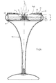
- Figure 1 shows a cross section of the paraffin lamp (1) with an iron bowl (2).
- A is centered in the iron bowl (2) incombustible wick (3) arranged in a riser (4) is held.
- the riser is in meltable Fuel (W) immersed and from a cylindrical incombustible casing (5).
- the riser (4) consists of spirally wound, two-layer corrugated film composite material made of thin metal with vertical cavities (6C), that arise from the corrugated structure of the one film. Between a narrow inflow gap extends the individual winding paths (F1) spiraling from the sheath (5) to the wick (3).
- the wick (3) is kept wrapped in the spiral center.
- Fuel (W) is poured into the iron bowl (2) melted by the riser (4, 4A) the wick (3) supplied by the liquid in the vertical cavities (6C) Fuel flows and flows capillary-like through the inflow joint (F1) to the wick (3).
- a glass fiber film (9) covering, spread out.
- On the glass fiber film (9) is one with Flow holes provided heat-conducting foil (11) made of metal applied, which the sheath (5) and in the iron shell (2) Filled fuel (W) contacted with heat.
- the case (5) with the riser (4) on the glass fiber film (9) arranged and designed to pass fuel.
- the container bottom (8) and the glass fiber film (9) are in this Execution circular.
- the heat-conducting film (11) is under Leave a riser footprint in which the Rising body (4) rests on the glass fiber film (9), circular.
- the flame is fed by the liquefied fuel (W).
- This liquefied fuel (W) is from the Vertical cavities (6C) from the glass fiber film (9), which with liquid fuel (W) is saturated.
- the Thermally conductive film (11) ensures that in the area of Glass fiber film (9) quickly a required melting temperature of the fuel (W) is reached and held so that a continuous flow of fuel takes place.
- the Iron bowl (2) is flat and has a diameter from 6 cm to 12 cm, preferably 8 cm.
- the iron bowl (2) is with a lid (14) with a flame opening (15), in this Representation with a toroidal section-shaped ring cover (14), lockable.
- the flame opening (15) comprising a glass cylinder (17) attached as a windscreen.
- the iron bowl (2) is on a stand (18) with a Carrier plate (20) arranged and on this by one Holding magnet (19) held.
- Fuel (W) in granular form, but also residues, e.g. Candle remains, fillable.
- the iron bowl (2) is through the Design warmed up quickly according to the invention.
- the flame receives oxygen through the central opening (15) in the Ring cover (14) and the supply air openings (7) in the casing (5), which in the area in which the riser (4) is not are enveloped, left.
- FIG 2 shows a plan view of the shell (5) with the Rising body (4) made of corrugated film composite material (6).
- the Rising body (4) consists of metallic, spiral wrapped two-ply corrugated film composite material (6) with vertical cavities (6C).
- the riser (4) is from the Envelope (5) wrapped.
- the corrugated film composite material (6) is made from a first, inner foil layer (6A) from a corrugated metal foil and a second, outside foil layer (6B) from a flat metal foil.
- the foil layers (6A, 6B) are advantageously glued together.
- the vertical cavities (6C), which serve the capillary-like fuel supply, are each from the first, inner wavy film layer (6A) formed and each of the second, outside Foil layer (6B) limited.
- the wick (3) is in the spiral center kept wrapped.
- the spiral arrangement of the vertical cavities (6C) enables a controlled and continuously spreading Heat distribution in the riser (4). About the invisible this metal heat is in the entire container submitted. Extends between the individual winding courses a narrow inlet joint (F1) through which liquid fuel is transportable.
- Figure 3 shows a cross section of the shell (5) with riser (4) made of corrugated film composite material (6).
- the casing (5) has one Inner diameter (SI) between 14 mm and 24 mm, preferably 17 mm and an annular collar at the top and bottom (12, 12A), the diameter (KD) of 16 mm to 30 mm, preferably Is 22 mm.
- This riser is also suitable for the usual ones To design tealight containers and use them there.
- a riser sleeve height (HH) of the sleeve (5) is 8 mm to 20 mm, preferably 16 mm and is greater than a riser height (KH) of the riser (4), which is 4 mm to 15 mm, preferably 8 mm is.
- a wick height (DH) of the wick (3) corresponds at least the envelope height (HH), wherein in the envelope (5) in the Area in which this does not envelop the riser (4), Supply air openings (7) are left.
- the height of the flame corresponds to the wick height (DH).
- the wick height (DH) is variably definable.
- the flame is liquefied by the Fuel fed. This liquefied fuel is used by the vertical cavities (6C) from the invisible Glass fiber foil, which is saturated with liquid fuel, absorbed.
- Figure 4 shows a cross section of the paraffin lamp (1A) with a plastic shell (2A).
- the paraffin lamp (1A) is Cup-like container (2A) a plastic shell (2A), the Diameter is 6 cm to 10 cm, preferably 10 cm and their Height is 15 mm to 25 mm, preferably 19 mm.
- the Plastic shell (2A) In the middle of the plastic shell (2A) is the sleeve (5) with the Rising body (4) and inner wick (3) arranged.
- the Plastic shell (2A) is one by a cover (14A) Flame opening (15) closed.
- the lid (14A) is double-walled. In the double wall are air permeable Scented films (21) introduced and fragrance outlet openings (40) embedded. When the fragrance films (21) are heated, a Corresponding fragrance aroma from the fragrance outlet openings (40) Approved.
- the plastic shell (2A) has one up to the cover (14A) Distance (A), which is greater than the height of the riser (KH).
- A Distance
- W Fuel
- G granulate
- a Paraffin glass can be fitted up to the full height (H) Space can be used, with a center hole that is larger than the upper diameter of the riser cylinder (5) is in the Fuel disks is provided.
- the design of the container (2A) made of plastic is a less heat loss achieved. With appropriate cuts of the heat-conducting foils not visible here are sections in the Plastic container (2A) definable, which last warmed up become.
- Figure 5 shows a cross section of the paraffin lamp (1B) with a wax crucible (22).
- Wax melting crucible (22) made of metal via a swivel arrangement (23A, 23B, 23C) to and away from the flame arranged.
- the swivel arrangement (23A, 23B, 23C) consists of a c-shaped bracket (23A), which has one end on the Container (2B) is rigidly arranged, another end Bearing bush (23B) and one on the wax crucible (22) arranged pivot pin (23C).
- the Bearing bush (23B) is vertical over a in the container cover (14B) recessed inlet opening (26) aligned.
- the pivot plug-in journal (23C) of the wax melting brick (22) which is hollow as a drain pipe (23C) is trained.
- the wax crucible (22) is eccentric the swivel plug-in journal (23C).
- the wax crucible (22) is heated and by the flame hence the fuel (W) contained therein is melted.
- the molten fuel (W) drips into the as shown Container (2B) and the wick (3) over the riser (4) fed.
- the Wax melting pot (22) pivoted into a hardening position, in which pivots the heat absorption surface (24) from the wick (3) is.
- the drain pipe (23C) is in each pivot position of the Wax melting pot (22) over the inlet opening (26) aligned. In the hardening position, this hardens in the Wax melting crucible (22) containing fuel (W), so that a flow into the container (2B) is quickly stopped.
- the Wax melting pot (22) preferably has a volume which the volume in the container (2B) up to the top of the Rising body (4) corresponds.
- the swivel / plug-in bearing pin (23C) of the wax crucible (22) can be pulled out of the bearing bush (23B).
- the wax crucible (22) is simple to design from the container (2B) removable and e.g. to clean.
- the Wax melting pot (22) is with granules, but also with Candle remains can be loaded.
- Figure 6 shows a cross section of the riser (4A) with a Cannula (28) and an associated tealight paraffin compact (P) arranged in a tea light container (TB).
- the metal one Rising body (4A) is designed as a cannula (28).
- the wick (3) is held on the flame side.
- the cannula (28) is on the flame side and on the bottom side of the relationship, respectively ring-shaped, preferably flat and funnel-shaped at the top has a slit-like vertical wax inflow joint (F2), of which one side edge is visible.
- the riser (4A) is off Copper or brass with a wall thickness (WS) of 0.15 mm to 0.2 mm and has a height (H) of 13 mm to 20 mm, preferably 16 mm.
- the cannula (28) has an inner diameter (ID) from 1 mm to 5 mm, preferably 2.5 mm, corresponding to the Wick diameter in loose fit.
- the flame and / or bottom annular extension (30A, 30B) has a diameter (D) of 8 mm to 16 mm, preferably 9 to 12 mm.
- the wax inflow joint (F2) is all over Length of the cannula (28) and the base extension (30B) formed, the bottom extension (30B) to the Envelope (5) is enough.
- the bottom extension (30B) and the Metal disc ring (31) serve as an enlarged Heat exchange surface.
- the flame side extension (30A) serves as Heat exchange surface that absorbs radiant heat and the cannula (28), especially early on after the flame was lit, the Wax feeds in the vicinity of the wick.
- the liquefied Fuel flows through the wax inlet joint (F2) into the Cannula (28) and rises through the wick. Besides, will the fuel in the cannula (28) capillary-like the wick (3) and
- the cannula (28) has the advantage that that of the upper ring (30A) heat taken directly into the wick zone is, which makes the fuel gas particularly in the lower range Firing zone is strongly heated, which is a more complete Burns as usual.
- the single piece of the cannula with the plate-shaped or ring-shaped extensions on the side (30A, 30B) and their thin walls are crucial Significance for the early and sustainable defrost function.
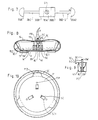
- FIG. 7 shows a punched blank made of thin sheet metal that passes through an embossing process in the area of the two cannula halves (28C, 28D) is formed semi-cylindrical and then along the dashed or dash-dotted lines folded back and forth is so that the two extensions are folded Add (30A1, 30A2; 30B1, 30B2) from the halves.
- Bottom side a further heat-conducting plate (31A) is directly molded on, which also the heat distribution and the attachment to the Fleece plate and the capillary feed of the last wax residue serves.
- Shaped cabinet clips (S) that hold the cannula together.
- the heat conducting plate (31A) has in the middle Opening the hatchbacks (S1), which is the fastening in the fleece to give a hold in brackets.
- Figure 8 shows a cross section of the paraffin candlestick in one first version with an iron bowl (2C).
- an iron bowl In the iron bowl an incombustible wick (3C) is arranged in the center, which in a riser (4C) is held.
- the climbing body is in meltable fuel (W) immersed.
- the container bottom (8) On the container bottom (8) is one with flow holes provided heat-conducting plate (11) made of thin sheet metal spaced placed, which the riser (4C) and in the Iron bowl (2C) filled fuel (W) thermally conductive contacted.
- the riser (4C) is on the heat conducting plate (11) by means of holding tabs bent up from openings (5C1) (5C) kept plugged in.
- the container bottom (8) is circular in this embodiment.
- the Thermally conductive plate (11) is essentially circular trained and with lateral support webs (11Z) on the container (2C) supported near the edge of the inwardly curved edge.
- the heat-conducting plate (11) is designed as a holding plate, by angled receiving tabs (5C) from the openings (5C1) for receiving ribs (41) formed on the riser (4C) are set up.
- the thermal plate (11) is small with bent foot-like spacing (11P) provided so that a fuel supply gap to the tank bottom (8) remains and the heat brought down does not go directly into the Metellic soil only crosses after burning enough fuel is melted.
- a Thermal insulation fleece between the heat conducting plate and the tank bottom serve as spacers and fuel transporters.
- the iron bowl (2C) is flat and has a diameter from 6 cm to 12 cm, preferably 9 cm.
- the flame becomes constant fed with liquid fuel (W) as in the wick (3C) the liquid fuel (W) is drawn in. After one Extinguishing the flame hardens the fuel (W) quickly, so that when the flame is lit again, sufficient fuel (W) is available in the wick (3C).
- a pipe section of approximately 15 mm in diameter is from three sides in the lower area to three wing-like Support ribs (41) pressed together, in the lower section of about 5 mm high, the cannula (28) is formed in which the wick (3C) is held. Between the three ribs (41) is over the Cannula (28) of the funnel attachment (7C) is formed. In its lower area are the supply air openings (8C) with about 1 to 1.5 mm diameter punched or cut and indented or drilled. The inflow gap (FC) for the Fuel is formed in each of the support ribs (41) are each pressed down to this gap.
- FC inflow gap
- the wick (3C) is made of quartz glass fiber and with a Wire helix (3H) made of highly heat-resistant material with larger turns than the wire diameter surrounds and carries end a horizontal end turn (3W) to protect the wick.
- a Wire helix (3H) made of highly heat-resistant material with larger turns than the wire diameter surrounds and carries end a horizontal end turn (3W) to protect the wick.
- Figure 10 shows a plan view of the container (2C) in which the Thermally conductive plate (11) is arranged.
- the three distance stamps (11P) provide a ground clearance, and the three Centering tabs (11Z) form a hold to the upper one Container area.
- Retaining tabs are from the heat-conducting plate (11) (5C) formed vertically standing by its material Breakthroughs (5C1) is bent out.
- the retaining tabs (5C) are embossed in the shape of a wedge on the outside, so that they fit the picture to the support ribs of the riser (4C).
- Figure 11 shows a cross section of the paraffin lamp in a second execution.
- it is cup-like Container (2D) a metal or plastic shell, the Diameter is 5 to 10 cm, preferably 7 cm and their Height is 15 to 25 mm, preferably 19 mm.
- a heat conducting plate (11) is arranged, the centering tabs (11Z) on the edge of the container (2D) on the one hand supported on the top and on the other hand on a curved one Container ring bead (2R) slightly spaced from the container bottom is held.
- the middle is on the heat-conducting floor (11) Rising body (4D) arranged with a sheet metal blank a central ring (7R) and radial approaches by embossing and Folds is shaped.
- the riser (4D) formed at the bottom a cannula section (28) which Sheet metal segments (7S) formed with gaps in between is.
- the sheet metal segments are closed on the heat conducting plate (11) Holding tabs (40D) spread apart and there with cut-out holding tabs (5D) fixed.
- the area of the riser (4D) represents the funnel attachment (7D) and is formed from a ring area, to which upwards curved wide tabs (7F) with gaps in between connect.
- the wick (3D) has a quartz glass fiber braided tubular jacket and an absorbent Quartz glass fiber core.
- Figure 12 shows the shell (2D) in supervision and in it fixed heat conducting plate (11) with the centering tabs (11Z).
- the funnel area is formed from the ring zone (7R) and sets continue upwards with the wide extensions (7F).
- the narrow stripes will pass the funnel (7S) bent down and brought together to form the segments of the cannula.
- the end sections are kinked on the heat conducting plate (11) spread out and punched out there by punching (5D1) Cabinet brackets (5D) fixed.
- Figure 13 shows a cross section of a third embodiment of the Lamp.
- the bowl (2E) has a height up to the lid, which is greater than the height of the riser. Especially there is a spare space for fuel at the edge (W) created.
- the room When fitted with a paraffin disc (P) the room can be used up to the full height, whereby a Center hole that is larger than the top diameter of the Funnel approach (7E) is in the fuel disc (P) is provided.
- a paraffin supernatant (PA1) protrudes in the funnel attachment (7E).
- the thickness of the paraffin disc (P) is less than the height of the Rising body, so that a refill before the complete Burning the container empty can be done. Just every now and then again an empty burn is required so that the wick from the Residue is annealed.
- the riser (4E) has a cannula (28) consisting of three Segments is folded. It is in a tealight Container (2E) arranged.
- the metal riser (4E) is out a sheet metal blank, Fig. 8, formed.
- the wick (3E) is held on the flame side.
- the cannula (28) is flared on the flame side from a ring area shaped. Between the cannula segments are slit-like Leave vertical wax inflow joints (FE), one side edge of which is visible. These joints (FE) extend into the Bottom area of the funnel attachment (7E) and are there as Funnel openings (8E) for supplying the residual flame (FR), shown in dashed lines, expanded.
- the riser (4E) is made of copper or brass with a wall thickness (WS) of 0.15 mm to 0.25 mm and has a height of 13 mm to 20 mm, preferably 16 mm.
- the cannula (28) has an inner diameter from 1 mm to 5 mm, preferably 2.5 mm, which the dem Wick diameter in loose fit corresponds.
- the flame-side funnel attachment (7E) serves as Heat exchange surface that absorbs radiant heat and the cannula (28), especially early on after lighting the flame, the Wax feeds in the vicinity of the wick.
- the liquefied Fuel flows through the wax inlet joint (FE) into the Cannula (28) and rises through the wick. Besides, will in the cannula (28) the fuel capillary-like the wick (3E) and fed to the flame.
- the wick consists of one braided quartz glass fiber jacket with an absorbent Quartz glass fiber core.
- Figure 14 shows a plan view in an enlarged view of the Thermally conductive plate (11) through the stampings (11P) from the bottom are kept spaced.
- the riser (4E) attached by using cabinet brackets (40E) in the bottom Openings (5E1) of the heat-conducting plate (11) is held.
- the area of the cannula (28E) consists of three cannula segments folded up, folded onto the side support webs (41E) and from which the cabinet brackets (40E) extend angled. Are between the cannula segments (28E) leave small inflow joints (FE).
- FIG. 15 shows a punch cut from thin sheet metal that passes through an embossing process in the area of the three cannula segments (28K) and of the funnel attachment (7E) is deformed and then along the dashed or dash-dotted lines is folded so that the intermediate sections are fully folded (28Z) on the outside of the funnel attachment (7E) and the Funnel openings and the inflow joints arise.
- radial support bars (28K) (41E) and cabinet clips (40E) are formed at the bottom, which also the heat distribution and the attachment to the Serve as a heat-conducting plate.
- the lights described can also be waxed or Operate stearin or with combustible vegetable fat.
Landscapes
- Engineering & Computer Science (AREA)
- Chemical & Material Sciences (AREA)
- Combustion & Propulsion (AREA)
- Mechanical Engineering (AREA)
- General Engineering & Computer Science (AREA)
- Non-Portable Lighting Devices Or Systems Thereof (AREA)
- Compositions Of Macromolecular Compounds (AREA)
- Lubricants (AREA)
- Cosmetics (AREA)
Claims (22)
- Lampe, notamment lampe fonctionnant avec de la paraffine (1, 1A - 1E), avec un récipient en forme de coupe (2, 2A - 2E) dans lequel une mèche incombustible (3, 3C - 3D) est centrée, laquelle est maintenue dans un corps ascendant (4, 4A, 4C - 4E) à parois métalliques fines, hors duquel elle fait saillie du côté de la flamme, ce corps ascendant (4, 4A, 4C - 4E), qui la contacte et l'entoure de toutes parts en laissant une rainure d'écoulement étroite (F1, F2, FC, FE), transmet la chaleur de fusion à la matière de combustion (W) contenue dans la coupe (2, 2A - 2E) de sorte que la masse fondue s'écoule vers la mèche (3, 3C - 3E), la partie inférieure du corps ascendant (4C, 4D, 4E) étant conçue en forme de canule (28) qui, s'élargissant en direction de la flamme, comprend une pièce en forme d'entonnoir (7C, 7D, 7E) d'environ 10 à 15 mm de hauteur que dépasse la mèche (3C, 3D, 3E) de sorte que, lors d'une alimentation à plein en matière combustible, la flamme (F) s'étend à l'extrémité inférieure jusqu'à la pièce en forme d'entonnoir (7C, 7D, 7E) ou approximativement dans celle-ci,
caractérisée en ce que
des orifices (8C, 8D, 8E) sont pratiqués dans la pièce en forme d'entonnoir (7C, 7D, 7E), dans la zone inférieure, proche de la mèche, et sont dimensionnés de sorte qu'elles suffisent, lors de la combustion d'un reste de matière combustible, à l'alimentation en air d'une petite flamme résiduelle (FR) brûlant dans la pièce en forme d'entonnoir (7C, 7D, 7E) et que la mèche (3C, 3D, 3E) consiste en fibres de verre quartzeux et que la canule (28, 28E), sa pièce en forme d'entonnoir (7D, 7E) et les attaches (40D, 40E), formées d'une pièce à partir d'elle, consistent en une pièce matricée, pliée. - Lampe selon la revendication 1,
caractérisée en ce que
la pièce matricée est une pièce découpée qui présente une bague centrale pour la formation de la pièce en forme d'entonnoir (7E, 7R) et des ailes radiales (28Z, 28K; 7S), qui s'étendent parallèlement à la pièce en forme d'entonnoir et sont conçues sous forme de segments de canule (28K, 7S), ainsi qu'un bras de maintien (40D) ou un pont d'appui (41E) à partir de laquelle une attache (40E) est formée. - Lampe selon la revendication 2,
caractérisée en ce que
la rainure d'écoulement (FD, FE) s'étend sur toute la longueur de la canule (28) entre les segments de celle-ci et est prolongée en forme d'ouverture (8D, 8E) de l'entonnoir et que des prolongements (7F) s'étendent vers le haut, à partir de l'anneau central de la piècce en forme d'entonnoir (7D). - Lampe selon l'une des revendications 1 à 3,
caractérisée en ce que
le corps ascendant (4C, 4D, 4E) est exécuté en métal, notamment en métal léger, cuivre ou laiton, d'une épaisseur de paroi de 0,15 mm à 0,25 mm, et que la canule (28) présente une hauteur d'environ 5 mm et un diamètre intérieur qui correspond au diamètre de la mèche en ajustement lâche. - Lampe selon l'une des revendications précédentes,
caractérisée en ce que
le corps ascendant (4C, 4D, 4E) est maintenu sur une plaque conductrice de chaleur (11) en tôle métallique mince à l'aide d'attaches (5C, 5D, 5E) recourbées, formées à partir d'elle et que la plaque conductrice de chaleur (11) est disposée, maintenue à faible distance du fond (8) du récipient par un intercalaire calorifuge ou des écarteurs (11P) estampés dans la plaque conductrice de chaleur (11) ou un bord d'appui (2R) présenté par le récipient (2D). - Lampe selon la revendication 5,
caractérisée en ce que
la plaque conductrice de chaleur (11) est sensiblement circulaire et est pourvue d'attaches latérales de centrage (11Z) dont les extrémités portent contre le récipient (2C, 2D, 2E), à proximité de son bord arrondi. - Lampe selon l'une des revendications précédentes,
caractérisée en ce que
le récipient (2C, 2E) est recouvert d'un couvercle (14) présentant une ouverture (15) pour la flamme, ce couvercle étant de préférence un couvercle circulaire (14) toroïdal, et peut être complètement fermé à l'aide d'un éteignoir. - Lampe selon la revendication 1,
caractérisée en ce que
la mèche (3C) est renforcée par une spirale en fil métallique (3H) ou par un tube en verre quartzeux, tressé. - Lampe selon la revendication 8,
caractérisée en ce que
la spirale en fil métallique (3C) présente, à hauteur de l'extrémité supérieure de la mèche (3C), une spire fermée. - Lampe selon la revendication 7,
caractérisée en ce que
le récipient (2) est une coupe plate en fer (2) dont le diamètre est de 6 cm à 12 cm, de préférence 8 cm. - Lampe selon la revendication 7 oui 10,
caractérisée en ce que
un dispositif de protection contre les courants d'air (17), de préférence un cylindre en verre (17), encerclant l'ouverture (15), prévue pour le flamme, est enfiché sur le couvercle annulaire (14). - Lampe selon la revendication 10 ou 11,
caractérisée en ce que
la coupe en fer (2) est maintenue magnétiquement sur un support (18) avec une plaque d'appui (20) et un aimant de fixation (19). - Lampe (1A) selon l'une des revendications 1 à 6,
caractérisée en ce que
le récipient (2A) est une coupe en matière plastique (2A) dont le diamètre est de 6 cm à 10 cm, préférentiellement de 10 cm, et la hauteur de 15 à 25 mm, préférentiellement de 19 mm. - Lampe (1A) selon la revendication 13,
caractérisée en ce que
la coupe en matière plastique (2A) peut être fermée avec un couvercle (14A) présentant une ouverture centrale (15) pour la flamme. - Lampe (1A) selon la revendication 14,
caractérisée en ce que
le couvercle (14A) est à double paroi et que des feuilles odoriférantes (21) peuvent être insérées dans le couvercle. - Lampe (1B) selon l'une des revendications précédentes,
caractérisée en ce que
le récipient (2B) est équipé d'une coupelle en métal (22) pour la fonte de la cire, laquelle coupelle (22) peut être pivotée à l'aide d'un dispositif d'orientation (23A, 23B, 23C) de sorte que, dans une position de fonte, une surface d'absorption de chaleur (24) de la coupelle (22) est disposée verticalement au-dessus de la mèche (3) tandis qu'un tube d'écoulement (23C) de la coupelle (22) est disposé verticalement au-dessus d'une ouverture d'entrée (26) du récipient (2B). - Lampe (1B) selon la revendication 16,
caractérisée en ce que
un anse (23A) est relié rigidement, par l'une de ses extrémités au récipient (2B) et est pourvu à son autre extrémité d'un coussinet (23B) qui est disposé verticalement au-dessus de l'ouverture d'entrée (26)
et qu'un tourillon de palier fermé orientable (23C), creux, conçu en forme de tube d'écoulement (23C), est inséré dans le coussinet (23B)
et que la coupelle (22) est montée excentriquement sur le tourillon de palier fermé orientable (23C) de sorte qu'en position de fonte la surface d'absorption de chaleur (24) de la coupelle (22) est disposée verticalement au-dessus de la mèche (3) et pivotée à l'écart de la mèche (3) en position de durcissement, le tube d'écoulement (23C) étant disposé au-dessus de l'ouverture d'entrée (26) dans chaque position d'orientation de la coupelle (22). - Lampe (1B) selon la revendication 16 ou 17,
caractérisée en ce que
la coupelle de fonte (22) a un volume qui correspond au volume du récipient (2B) quand celui-ci est rempli jusqu'au bord supérieur du corps ascendant (4). - Lampe selon l'une des revendications 16, à 18,
caractérisée en ce que
le tourillon du palier fermé orientable (23C) due la coupelle (22) peut être retiré hors du coussinet (23B). - Lampe (1B) selon l'une des revendications 16 à 18,
caractérisée en ce que
un filtre en fibres de verre (27) est inséré dans la coupelle (22) en amont du tube d'écoulement (23C). - Lampe selon la revendication 1,
caractérisée en ce que
la pièce matricée comprend une plaque inférieure, métallique (31A) et des languettes (S1, S). - Lampe selon l'une des revendications précédentes,
caractérisée en ce que
cette lampe est une bougie pour chauffe-plats de dimensions courantes dans le commerce, laquelle est équipée d'un corps en paraffine circulaire (P) dont le fond présente une perforation centrale un peu plus large que le diamètre de la pièce en forme d'entonnoir (7E), la partie (PA1) du corps de paraffine surplombant la perforation s'enfonçant de quelques millimètres dans la pièce en entonnoir (7E) dont elle épouse la forme tout en laissant un passage pour la mèche, et l'épaisseur étant inférieure à la hauteur du corps ascendant (4E).
Applications Claiming Priority (7)
| Application Number | Priority Date | Filing Date | Title |
|---|---|---|---|
| DE19944425179 DE4425179A1 (de) | 1994-07-16 | 1994-07-16 | Paraffinleuchte |
| DE4425179 | 1994-07-16 | ||
| DE19505420 | 1995-02-18 | ||
| DE19505420 | 1995-02-18 | ||
| DE1995108962 DE19508962A1 (de) | 1994-07-16 | 1995-03-13 | Paraffinleuchte |
| DE19508962 | 1995-03-13 | ||
| PCT/EP1995/002792 WO1996002794A1 (fr) | 1994-07-16 | 1995-07-17 | Lampe, notamment lampe fonctionnant avec de la paraffine |
Publications (2)
| Publication Number | Publication Date |
|---|---|
| EP0771403A1 EP0771403A1 (fr) | 1997-05-07 |
| EP0771403B1 true EP0771403B1 (fr) | 1999-02-10 |
Family
ID=27206587
Family Applications (1)
| Application Number | Title | Priority Date | Filing Date |
|---|---|---|---|
| EP95926906A Expired - Lifetime EP0771403B1 (fr) | 1994-07-16 | 1995-07-17 | Lampe, notamment lampe fonctionnant avec de la paraffine |
Country Status (5)
| Country | Link |
|---|---|
| EP (1) | EP0771403B1 (fr) |
| AT (1) | ATE176721T1 (fr) |
| AU (1) | AU3112295A (fr) |
| DE (1) | DE59505096D1 (fr) |
| WO (1) | WO1996002794A1 (fr) |
Families Citing this family (36)
| Publication number | Priority date | Publication date | Assignee | Title |
|---|---|---|---|---|
| US7467945B2 (en) | 2004-09-10 | 2008-12-23 | S.C. Johnson & Son, Inc. | Candle assembly and fuel element therefor |
| US7318724B2 (en) | 2004-09-10 | 2008-01-15 | S. C. Johnson & Son, Inc. | Wick holder and wick assembly for candle assembly |
| US7413435B2 (en) | 2004-09-10 | 2008-08-19 | S. C. Johnson & Son, Inc. | Fuel delivery method for melting plate candle |
| US7247017B2 (en) | 1999-12-21 | 2007-07-24 | S.C. Johnson & Son, Inc. | Melting plate candles |
| US7591646B2 (en) | 1999-12-21 | 2009-09-22 | S. C. Johnson & Son, Inc. | Heat exchange method for melting plate candle |
| US7442036B2 (en) | 2004-09-10 | 2008-10-28 | S.C. Johnson & Son, Inc. | Candle assembly and wick holder with improved capillary well for ensuring sustainable relight |
| US6780382B2 (en) | 1999-12-21 | 2004-08-24 | S.C. Johnson & Son, Inc. | Simmer plate dispenser for volatile active materials |
| US7497685B2 (en) | 2005-07-20 | 2009-03-03 | S.C. Johnson & Son, Inc. | Wick-holder assembly |
| US7524187B2 (en) | 2004-09-10 | 2009-04-28 | S.C. Johnson & Son, Inc. | Wick holder locking mechanism |
| US7229280B2 (en) | 2004-09-10 | 2007-06-12 | S.C. Johnson & Son, Inc. | Wick holder magnetic retention means |
| US7467944B2 (en) | 2004-02-17 | 2008-12-23 | S.C. Johnson & Son, Inc. | Candle assembly including a fuel element and a wick holder |
| USD550378S1 (en) | 2004-09-10 | 2007-09-04 | S.C. Johnson & Sons, Inc. | Melting plate with rose petal cut-outs |
| USD575885S1 (en) | 2005-07-19 | 2008-08-26 | S. C. Johnson & Son, Inc. | Melting plate for a decorative candleholder |
| US7287978B2 (en) | 2004-09-10 | 2007-10-30 | S.C. Johnson & Son, Inc. | Candle holder with improved air flow |
| US7607915B2 (en) | 2004-09-10 | 2009-10-27 | S.C. Johnson & Son, Inc. | Heat exchange method for melting plate candle |
| USD530838S1 (en) | 2004-09-10 | 2006-10-24 | S.C. Johnson & Son, Inc. | Decorative candle holder |
| USD533951S1 (en) | 2004-09-10 | 2006-12-19 | S. C. Johnson & Son, Inc. | Decorative candle holder |
| USD540962S1 (en) | 2004-09-10 | 2007-04-17 | S. C. Johnson & Son, Inc. | Melting plate with engraved spiral pattern |
| USD539942S1 (en) | 2004-09-10 | 2007-04-03 | S.C. Johnson & Son, Inc. | Melting plate with engraved rose petal pattern |
| USD534283S1 (en) | 2004-09-10 | 2006-12-26 | S.C. Johnson & Son, Inc. | Decorative candle holder |
| USD538450S1 (en) | 2004-09-10 | 2007-03-13 | S.C. Johnson & Son, Inc. | Decorative candle holder |
| USD534282S1 (en) | 2004-09-10 | 2006-12-26 | S.C. Johnson & Son, Inc. | Decorative candle votive-pebble |
| USD537178S1 (en) | 2004-09-10 | 2007-02-20 | S.C. Johnson & Son, Inc. | Melting plate with sun graphic cut-outs |
| USD575886S1 (en) | 2004-09-10 | 2008-08-26 | S.C. Johnson & Son, Inc. | Melting plate for a decorative candleholder |
| USD536108S1 (en) | 2004-09-10 | 2007-01-30 | S.C. Johnson & Son, Inc. | Flame-shaped wick clip |
| USD534666S1 (en) | 2004-09-10 | 2007-01-02 | S.C. Johnson & Sons, Inc. | Decorative candle holder |
| USD541443S1 (en) | 2005-01-28 | 2007-04-24 | S. C. Johnson & Son, Inc. | Decorative candle holder |
| USD577136S1 (en) | 2005-05-06 | 2008-09-16 | S.C. Johnson & Son, Inc. | Decorative candleholder |
| USD577447S1 (en) | 2005-05-06 | 2008-09-23 | S.C.. Johnson & Son, Inc. | Decorative candleholder |
| USD576750S1 (en) | 2005-05-06 | 2008-09-09 | S.C. Johnson & Son, Inc. | Decorative candleholder |
| USD576319S1 (en) | 2005-05-06 | 2008-09-02 | S.C. Johnson & Son, Inc. | Melting plate for a decorative candleholder |
| USD533952S1 (en) | 2005-05-06 | 2006-12-19 | S.C. Johnson & Son, Inc. | Decorative candle holder |
| USD576751S1 (en) | 2005-05-06 | 2008-09-09 | S.C. Johnson & Son, Inc. | Decorative candleholder |
| USD576752S1 (en) | 2005-05-06 | 2008-09-09 | S.C. Johnson & Son, Inc. | Decorative candleholder |
| USD575884S1 (en) | 2007-05-22 | 2008-08-26 | S.C. Johnson & Son, Inc. | Decorative candleholder |
| KR102354486B1 (ko) * | 2021-10-20 | 2022-01-21 | 안상권 | 연료공급부를 포함하는 캔들 |
Family Cites Families (6)
| Publication number | Priority date | Publication date | Assignee | Title |
|---|---|---|---|---|
| US3910753A (en) * | 1974-04-15 | 1975-10-07 | George Y Lee | Wax burner |
| GB1514338A (en) * | 1974-08-01 | 1978-06-14 | Tsuda Kiichi | Containerized wax candle |
| DE2440068A1 (de) * | 1974-08-21 | 1976-03-18 | Freiburger Wachswarenfabrik Bi | Brenneinsatz zur bildung eines kerzenfoermigen leuchtkoerpers |
| US4084086A (en) * | 1976-03-22 | 1978-04-11 | David Bandel | Solid fuel lamp |
| DE3113067A1 (de) * | 1980-07-10 | 1982-02-18 | Gerd 7000 Stuttgart Knobel | "dochteinsatz fuer einen mit brennbarer masse, vorzugsweise wachs, gefuellter behaelter |
| DE4241292A1 (de) * | 1992-02-08 | 1994-06-09 | Schirnecker Hans Ludwig | Dauerbrenn-Licht |
-
1995
- 1995-07-17 AT AT95926906T patent/ATE176721T1/de not_active IP Right Cessation
- 1995-07-17 DE DE59505096T patent/DE59505096D1/de not_active Expired - Fee Related
- 1995-07-17 WO PCT/EP1995/002792 patent/WO1996002794A1/fr not_active Ceased
- 1995-07-17 EP EP95926906A patent/EP0771403B1/fr not_active Expired - Lifetime
- 1995-07-17 AU AU31122/95A patent/AU3112295A/en not_active Abandoned
Also Published As
| Publication number | Publication date |
|---|---|
| EP0771403A1 (fr) | 1997-05-07 |
| WO1996002794A1 (fr) | 1996-02-01 |
| ATE176721T1 (de) | 1999-02-15 |
| DE59505096D1 (de) | 1999-03-25 |
| AU3112295A (en) | 1996-02-16 |
Similar Documents
| Publication | Publication Date | Title |
|---|---|---|
| EP0771403B1 (fr) | Lampe, notamment lampe fonctionnant avec de la paraffine | |
| DE4425179A1 (de) | Paraffinleuchte | |
| DE19508962A1 (de) | Paraffinleuchte | |
| US6802707B2 (en) | Melting plate candles | |
| WO1993016153A1 (fr) | Lampe a eclairage permanent | |
| EP1564485A2 (fr) | Bougies à plaque de fusion | |
| CA2617988A1 (fr) | Charge de combustible pour bougie a plateau de fusion et procede d'apport de combustible liquefie a une meche | |
| WO2001045756A1 (fr) | Diffuseur comprenant une plaque a faible ebullition destine a des matieres actives | |
| DE4203644A1 (de) | Dauerbrenn-licht | |
| WO1997004273A1 (fr) | Lampe a paraffine | |
| EP1406673A1 (fr) | Dispositif pour la vaporisation et la diffusion d'huiles | |
| WO2008042237A1 (fr) | Bougie et support de mèche associé | |
| AU2005284935B2 (en) | Improved heat exchange for melting plate candle | |
| DE2440068A1 (de) | Brenneinsatz zur bildung eines kerzenfoermigen leuchtkoerpers | |
| DE202009003812U1 (de) | Leuchte mit Hülse zur Aufnahme eines Dochtes | |
| DE102023205512B4 (de) | Brennstoffbehälter für ein Tischfeuer | |
| EP1715899B1 (fr) | Dispositif de liberation d'un parfum pour lampe a huile et meche | |
| EP1797367B1 (fr) | Systeme pour ameliorer l'approvisionnement en combustible dans une bougie a plateau de fusion | |
| EP1807658A1 (fr) | Chandelle a recipient ameliore | |
| DE202011106037U1 (de) | Vorrichtung zum Verbrennen von Kerzenresten | |
| EP1484551A1 (fr) | Lampe | |
| WO2024175276A1 (fr) | Réservoir de combustible pour un foyer de table | |
| DE19844224A1 (de) | Leuchte mit Schmelzvorrichtung | |
| DE2656286A1 (de) | Wachskerzenhalter | |
| WO1994025793A1 (fr) | Bougie a flamme permanente |
Legal Events
| Date | Code | Title | Description |
|---|---|---|---|
| PUAI | Public reference made under article 153(3) epc to a published international application that has entered the european phase |
Free format text: ORIGINAL CODE: 0009012 |
|
| 17P | Request for examination filed |
Effective date: 19970123 |
|
| AK | Designated contracting states |
Kind code of ref document: A1 Designated state(s): AT BE CH DE DK ES FR GB IE IT LI NL SE |
|
| GRAG | Despatch of communication of intention to grant |
Free format text: ORIGINAL CODE: EPIDOS AGRA |
|
| GRAG | Despatch of communication of intention to grant |
Free format text: ORIGINAL CODE: EPIDOS AGRA |
|
| GRAH | Despatch of communication of intention to grant a patent |
Free format text: ORIGINAL CODE: EPIDOS IGRA |
|
| 17Q | First examination report despatched |
Effective date: 19980717 |
|
| GRAH | Despatch of communication of intention to grant a patent |
Free format text: ORIGINAL CODE: EPIDOS IGRA |
|
| GRAA | (expected) grant |
Free format text: ORIGINAL CODE: 0009210 |
|
| AK | Designated contracting states |
Kind code of ref document: B1 Designated state(s): AT BE CH DE DK ES FR GB IE IT LI NL SE |
|
| PG25 | Lapsed in a contracting state [announced via postgrant information from national office to epo] |
Ref country code: SE Free format text: THE PATENT HAS BEEN ANNULLED BY A DECISION OF A NATIONAL AUTHORITY Effective date: 19990210 Ref country code: NL Free format text: LAPSE BECAUSE OF FAILURE TO SUBMIT A TRANSLATION OF THE DESCRIPTION OR TO PAY THE FEE WITHIN THE PRESCRIBED TIME-LIMIT Effective date: 19990210 Ref country code: IT Free format text: LAPSE BECAUSE OF FAILURE TO SUBMIT A TRANSLATION OF THE DESCRIPTION OR TO PAY THE FEE WITHIN THE PRE;WARNING: LAPSES OF ITALIAN PATENTS WITH EFFECTIVE DATE BEFORE 2007 MAY HAVE OCCURRED AT ANY TIME BEFORE 2007. THE CORRECT EFFECTIVE DATE MAY BE DIFFERENT FROM THE ONE RECORDED.SCRIBED TIME-LIMIT Effective date: 19990210 Ref country code: GB Free format text: LAPSE BECAUSE OF NON-PAYMENT OF DUE FEES Effective date: 19990210 Ref country code: FR Free format text: LAPSE BECAUSE OF FAILURE TO SUBMIT A TRANSLATION OF THE DESCRIPTION OR TO PAY THE FEE WITHIN THE PRESCRIBED TIME-LIMIT Effective date: 19990210 Ref country code: ES Free format text: THE PATENT HAS BEEN ANNULLED BY A DECISION OF A NATIONAL AUTHORITY Effective date: 19990210 |
|
| REF | Corresponds to: |
Ref document number: 176721 Country of ref document: AT Date of ref document: 19990215 Kind code of ref document: T |
|
| REG | Reference to a national code |
Ref country code: CH Ref legal event code: EP |
|
| REG | Reference to a national code |
Ref country code: IE Ref legal event code: FG4D Free format text: GERMAN |
|
| REF | Corresponds to: |
Ref document number: 59505096 Country of ref document: DE Date of ref document: 19990325 |
|
| PG25 | Lapsed in a contracting state [announced via postgrant information from national office to epo] |
Ref country code: DK Free format text: LAPSE BECAUSE OF FAILURE TO SUBMIT A TRANSLATION OF THE DESCRIPTION OR TO PAY THE FEE WITHIN THE PRESCRIBED TIME-LIMIT Effective date: 19990510 |
|
| PGFP | Annual fee paid to national office [announced via postgrant information from national office to epo] |
Ref country code: CH Payment date: 19990623 Year of fee payment: 5 |
|
| NLV1 | Nl: lapsed or annulled due to failure to fulfill the requirements of art. 29p and 29m of the patents act | ||
| EN | Fr: translation not filed | ||
| PG25 | Lapsed in a contracting state [announced via postgrant information from national office to epo] |
Ref country code: AT Free format text: LAPSE BECAUSE OF NON-PAYMENT OF DUE FEES Effective date: 19990717 |
|
| PG25 | Lapsed in a contracting state [announced via postgrant information from national office to epo] |
Ref country code: BE Free format text: LAPSE BECAUSE OF NON-PAYMENT OF DUE FEES Effective date: 19990731 |
|
| GBV | Gb: ep patent (uk) treated as always having been void in accordance with gb section 77(7)/1977 [no translation filed] |
Effective date: 19990210 |
|
| PG25 | Lapsed in a contracting state [announced via postgrant information from national office to epo] |
Ref country code: IE Free format text: LAPSE BECAUSE OF NON-PAYMENT OF DUE FEES Effective date: 19991019 |
|
| REG | Reference to a national code |
Ref country code: IE Ref legal event code: FD4D |
|
| PLBE | No opposition filed within time limit |
Free format text: ORIGINAL CODE: 0009261 |
|
| STAA | Information on the status of an ep patent application or granted ep patent |
Free format text: STATUS: NO OPPOSITION FILED WITHIN TIME LIMIT |
|
| 26N | No opposition filed | ||
| BERE | Be: lapsed |
Owner name: SCHIRNEKER HANS-LUDWIG Effective date: 19990731 |
|
| PG25 | Lapsed in a contracting state [announced via postgrant information from national office to epo] |
Ref country code: LI Free format text: LAPSE BECAUSE OF NON-PAYMENT OF DUE FEES Effective date: 20000731 Ref country code: CH Free format text: LAPSE BECAUSE OF NON-PAYMENT OF DUE FEES Effective date: 20000731 |
|
| PGFP | Annual fee paid to national office [announced via postgrant information from national office to epo] |
Ref country code: DE Payment date: 20000829 Year of fee payment: 6 |
|
| REG | Reference to a national code |
Ref country code: CH Ref legal event code: PL |
|
| PG25 | Lapsed in a contracting state [announced via postgrant information from national office to epo] |
Ref country code: DE Free format text: LAPSE BECAUSE OF NON-PAYMENT OF DUE FEES Effective date: 20020501 |