EP0771407B1 - Örtliche kalibriervorrichtung für und verfahren zur korrektur von nichtlinearitäten eines strömungssensors - Google Patents
Örtliche kalibriervorrichtung für und verfahren zur korrektur von nichtlinearitäten eines strömungssensors Download PDFInfo
- Publication number
- EP0771407B1 EP0771407B1 EP95927187A EP95927187A EP0771407B1 EP 0771407 B1 EP0771407 B1 EP 0771407B1 EP 95927187 A EP95927187 A EP 95927187A EP 95927187 A EP95927187 A EP 95927187A EP 0771407 B1 EP0771407 B1 EP 0771407B1
- Authority
- EP
- European Patent Office
- Prior art keywords
- flow
- sensor
- values
- sensor unit
- air flow
- Prior art date
- Legal status (The legal status is an assumption and is not a legal conclusion. Google has not performed a legal analysis and makes no representation as to the accuracy of the status listed.)
- Expired - Lifetime
Links
- 238000000034 method Methods 0.000 title claims description 24
- 238000012937 correction Methods 0.000 title claims description 13
- 238000012360 testing method Methods 0.000 claims description 14
- 238000005259 measurement Methods 0.000 claims description 8
- 238000009434 installation Methods 0.000 claims description 5
- 238000009423 ventilation Methods 0.000 claims description 3
- 238000004590 computer program Methods 0.000 claims 1
- XLYOFNOQVPJJNP-UHFFFAOYSA-N water Substances O XLYOFNOQVPJJNP-UHFFFAOYSA-N 0.000 description 16
- 230000008569 process Effects 0.000 description 10
- 238000004891 communication Methods 0.000 description 8
- 230000006870 function Effects 0.000 description 6
- 238000010586 diagram Methods 0.000 description 5
- 238000012545 processing Methods 0.000 description 5
- 238000012546 transfer Methods 0.000 description 5
- 210000002569 neuron Anatomy 0.000 description 4
- XUIMIQQOPSSXEZ-UHFFFAOYSA-N Silicon Chemical compound [Si] XUIMIQQOPSSXEZ-UHFFFAOYSA-N 0.000 description 3
- 238000006243 chemical reaction Methods 0.000 description 3
- 229910052710 silicon Inorganic materials 0.000 description 3
- 239000010703 silicon Substances 0.000 description 3
- 230000003321 amplification Effects 0.000 description 2
- 238000004364 calculation method Methods 0.000 description 2
- 238000013461 design Methods 0.000 description 2
- 230000000694 effects Effects 0.000 description 2
- 238000004519 manufacturing process Methods 0.000 description 2
- 238000003199 nucleic acid amplification method Methods 0.000 description 2
- 230000004044 response Effects 0.000 description 2
- 230000000717 retained effect Effects 0.000 description 2
- 238000004378 air conditioning Methods 0.000 description 1
- 238000004458 analytical method Methods 0.000 description 1
- 230000008901 benefit Effects 0.000 description 1
- 230000008859 change Effects 0.000 description 1
- 230000008867 communication pathway Effects 0.000 description 1
- 230000002860 competitive effect Effects 0.000 description 1
- 239000000470 constituent Substances 0.000 description 1
- 230000001419 dependent effect Effects 0.000 description 1
- 230000007613 environmental effect Effects 0.000 description 1
- 238000010438 heat treatment Methods 0.000 description 1
- 238000010606 normalization Methods 0.000 description 1
- 238000004806 packaging method and process Methods 0.000 description 1
- 230000035945 sensitivity Effects 0.000 description 1
- 238000012956 testing procedure Methods 0.000 description 1
- 238000009966 trimming Methods 0.000 description 1
- 238000011144 upstream manufacturing Methods 0.000 description 1
Images


Classifications
-
- G—PHYSICS
- G01—MEASURING; TESTING
- G01F—MEASURING VOLUME, VOLUME FLOW, MASS FLOW OR LIQUID LEVEL; METERING BY VOLUME
- G01F25/00—Testing or calibration of apparatus for measuring volume, volume flow or liquid level or for metering by volume
- G01F25/10—Testing or calibration of apparatus for measuring volume, volume flow or liquid level or for metering by volume of flowmeters
- G01F25/15—Testing or calibration of apparatus for measuring volume, volume flow or liquid level or for metering by volume of flowmeters specially adapted for gas meters
-
- G—PHYSICS
- G01—MEASURING; TESTING
- G01F—MEASURING VOLUME, VOLUME FLOW, MASS FLOW OR LIQUID LEVEL; METERING BY VOLUME
- G01F1/00—Measuring the volume flow or mass flow of fluid or fluent solid material wherein the fluid passes through a meter in a continuous flow
- G01F1/05—Measuring the volume flow or mass flow of fluid or fluent solid material wherein the fluid passes through a meter in a continuous flow by using mechanical effects
- G01F1/34—Measuring the volume flow or mass flow of fluid or fluent solid material wherein the fluid passes through a meter in a continuous flow by using mechanical effects by measuring pressure or differential pressure
- G01F1/50—Correcting or compensating means
Definitions
- This invention relates to field programmable calibration devices and methods, and has particular application to inexpensive air flow sensor devices needing inexpensive calibration on-site, without having substantial processing power readily or continously available.
- US Patent Specification No. 4821557 describes real time quantitive analysis of gas stream constituents during meter proving.
- the present invention provides a method as defined in Claim 1 hereinafter.
- the present invention may provide one or more of the features defined in Claims 2 and 3 hereinafter.
- the present invention may provide a system as defined in Claim 4 as hereinafter.
- This invention allows low cost components to be utilized with individual zone controllers in buildings with Variable Air Volume (VAV) Heating and Air Conditioning systems without sacrificing sensed accuracy.
- VAV Variable Air Volume
- the sensing system is comprised of a mechanical pick-up assembly (11), interconnection tubing (1, 2) and a sensor (17).
- the mechanical assembly exhibits a non-linear transfer function (Velocity vs. Pressure) and differs with different duct sizes and manufacturers.
- Low cost sensors can be used to generate accurate measurement of air flow yet may exhibit a non-linear transfer function.
- This invention defines a process that allows low computational power processors to interact with the above mentioned flow conversion system and provide accurate readings without requiring extensive real time calculations.
- the actual transfer function of the pickup assembly may be different than the ideal due to turbulence-induced noise that may exist at the pickup assembly.
- the turbulence is caused by bends in the supply and/or exhaust duct work and is entirely site dependent. Therefore, a site commissioning process may be performed with actual test conditions to normalize the flow response regarding these effects.
- the correction for turbulence is typically conducted at minimal and maximum flow condition for the particular duct size.
- a third calibration point is provided to correct any null drift (at zero flow) associated with the sensor. This normalization set is stored in memory and is handled as an offset to the ideal linearized transfer function.
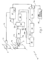
- Fig. 1 is a block diagram of the flow of information signals from the air flow duct/sensor to the control devices that operate because of the values read from the calibrated signal.
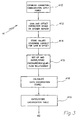
- Fig. 2 is a flow diagram of the steps employed in the preferred embodiment of this invention.
- Fig. 3 is a detailed flow diagram of a portion of Fig. 2.
- Fig. 4 is a detailed flow diagram of another portion of Fig. 2.
- Figs. 5a, 5b and 5c are curve plots.
- This invention allows for low cost compensation for pickup device nonlinearity, sensor nonlinearity, and nonlinearity introduced by silicon based electronics.
- the sensor pickup device itself 11, situated appropriately in the air duct 12 to measure the flow of passing air F to control the damper D forms the basis of the system 10 by which the measure of air flow may be used as one of the parameters in determining and controlling the amount of air flow and ultimately room temperature.
- the preferred embodiment was designed with a particular flow sensor in mind but this invention can be used with nearly any flow or pressure sensor of appropriate sensitivity and output.
- Fig. 1 More particularly how the system works is first described with reference to Fig. 1. Because the pickup device 11 locally restricts the air flow in the duct, there is an air pressure drop across the pickup device. Hoses 1 and 2 transfer the up and down stream air pressures to a low cost pressure/flow sensor 17. The relationship between the air flow and the pressure differential is non linear. Typically the pressure is a nearly a square root function of the air flow velocity rather than a linear relationship. The manufacturer of the pickup device commonly furnishes curves relating air flow and pressure drop, so no experimentation is needed. If one were to design his own pickup device such a relationship curve as shown in Figure 5 could easily be developed by those skilled in the art.
- the controller motor and actuator assemblage 13 is operated in response to a signal which is derived from control algorithm containing control system 27 and sent by system 27 across line 15 in order to actuate the damper D.
- the control may be through a distributed network of controllers like 27 or, alternatively, it could feed into a general purpose computer programmed to deliver an appropriate signal to actuators like actuator assemblage 13, or dedicated hardware or some combination as would be well understood by the ordinary practitioner of this art. For example, it could be a duly organized collection of electronic components responsive to upstream signals generated in accord with the remainder of the description of this device that generates a control signal responsive thereto.
- the controller 27 employs knowledge of the user desired setpoint (flow and temperature) together with the output 16 indicating the amount of air flow (preferably in feet per minute) to produce a control signal to send on line 15 (which may be any appropriate communication pathway) to actuator 13 so as to control the positioning of damper D.
- the controller may also be connected to a user interface and data logging device UID via communications path 15a, to keep the user informed of system operations.
- system 10 uses the resulting velocity (preferably expressed as a metres per second or m.p.s. signal value on line 16 to generate signals to actuate the damper (via line 15) and/or to report data out (via line 15a) to User Interface and Data logs).
- resulting velocity preferably expressed as a metres per second or m.p.s. signal value on line 16 to generate signals to actuate the damper (via line 15) and/or to report data out (via line 15a) to User Interface and Data logs).
- the pickup device 11 has two attached pressure hoses 1 and 2 which are connected to provide a flow of air across the flow sensor 17.
- the positioning of the hoses facing into and out of the air stream flow F to get a good representation of the flow is well known in the art.
- the flow sensor itself in the preferred embodiment is a micromachined silicon-based bridge structure which generally supports a wheatstone bridge configuration of resistors exposed to the flow of air in a predetermined pattern in an arrangement which has come to be well known in the art.
- the sensor converts the pressure differential into a differential voltage.
- the relationship of the pressure differential to the sensor output voltage while nearly a straight line is also somewhat non-linear. (Also, the flow sensor parameters vary greatly from unit to unit because of manufacturing tolerances, especially using the preferred for economy microbridge type sensor.)
- a number of different flow sensor bridges with input and output hoses or connectors to hoses are presently commercially available from the Micro Switch Division of Honeywell Inc.
- the output of each side of the bridge is provided to the inverting and noninverting inputs of an general amplification block op amp 18.
- This block in the preferred embodiment is assumed to incorporate some means for null and Full Scale Output adjustment such as is described by International Patent Application No. PCT/US94/14957 filed December 28. 1994; however, those of ordinary skill in the art can use potentiometer adjustments or laser trimming, or other adjustment schemes to adjust gain and offset as desired.
- amplifier block 18 The implementation of this amplifier block may preferably be accomplished using an application specific integrated circuit (ASIC) in which the silicon device required to implement the amplifier can cause some non-linearity.
- a multiplexor switch 23 selects one analog voltage value at a time to be converted to a digital count value.
- the control logic 27 causes the multiplexor switch to connect the analog to digital converter, 28, to one of the analog inputs 22a, 24 or 25. Since the analog to digital converter 28 may also be preferably implemented as part of an application specific integrated circuit, some of its characteristics may also be slightly non-linear.
- the digital count values outputs from the digital to analog converter may be stored in memory related to or part of a microprocessor [not shown separately, but included in box 27]. Analog to digital conversion of the flow sensor amplifier output and calibration voltage are repeated periodically since the air flow may change due to changes in damper position, changes in the air supply source pressure, and so forth.
- the output from the amplifier block 18 is input into a multiplexor 23 on line 22a.
- Multiplexor 23 has other control inputs 24 and reference voltage 25.
- the mux channel select input for line 26 is produced by the control logic 27.
- Line 26 may, of course, be multiple lines depending on the multiplexor configuration.
- the output of the multiplexor 23 goes to a A/D converter device 28.
- This device produces both reference voltage counts and flow sensor voltage counts across lines 28a and 28b, respectively.
- the flow sensor counts are corrected via reference voltage correction device 29, producing an output on 29a of a voltage level.
- This level is linearized (as described in detail later) using the linearization table 30 producing a metres per second representative signal 31 which must still be corrected (as described in detail later) by the three (in the preferred embodiment) field correction calibration points 32.
- the air velocity signal (FPM) is output on line 16 to the controller 27.
- Fig. 2 in which the abbreviated flow diagram 40 is shown, consisting of the steps of factory calibration 41, installation at the site 42, measurement at the site and storage of curve correction data 43, and final setup for runtime 44 to achieve the ready state 45.
- the steps 41 and/or 42 include a curve generating and storage of lookup table procedure that employs a substantial processor which is external to the installed device. In the preferred embodiment it is done in a program called CARETM (Honeywell Inc.) that is a software tool run on a general purpose computer which calculates the linearization table based on the input the user gives it. This is explained in more detail later, but it is important to note here that this curve and table generation can occur either at the factory or in the field (at the installation site).
- CARETM Honeywell Inc.
- Fig 3 describes the calibration and linearization processes which, as was described in the last paragraph, are between steps 41 and 42.
- the sensor and related electronics are first connected to power and communications in step 410.
- step 412 if calibration of gain and offset was not already done, it is done by whatever method is suitable to the source and application.
- the preferred embodiment substeps to 414 calibrate the analog inputs 17a and 17b, and save the necessary parameters in network variable nv_cal (saved in EEPROM) are given as follows: Apply power to the unit under test and connect an in-factory tester to the communications port (in the preferred embodiment a LonWorks port, available and trademark from Echelon). Establish communications with the diagnostics network variables in the unit under test on the LonWorks network. This requires a query_id for the neuron_id and knowing (by reading, preconfiguring or writing) the network image saved in EEPROM.
- the unit is ready for determination of calibration data by means of actually inputting pressures to the flow sensor across tubes 1 and 2 ( Figure 1). Then the voltage at 29a ( Figure 1) is read via the network for each pressure applied to the sensor. Then the values that were read should be stored in EEPROM or other semi-permanent memory via network variable nv_cal. In other words the flow sensor nonlinearity is to be measured and stored.
- si_flow_sen_volts_s12[ 0 ] voltage measured at zero metres (inches) of water
- si_flow_sen_volts_s12[ 1 ] voltage measured at 2 ⁇ 54 x 10 -2 metres (one inch) of water
- si_flow_sen_volts_s12[ 2 ] voltage measure at 5 ⁇ 08 x 10 -2 metres (two inches) of water
- si_flow_sen_in_s12[ 0 ] 2 ⁇ 54 x 10 -2 metres of water (one inch of water)
- si_flow_sen_in_s12[ 1 ] 5 ⁇ 08 x 10 -2 metres of water (two inches of water)
- THESE ARE THE POINTS 70 on figure 5a. They are saved in EEPROM at locations names nv_cal. (Zero metres (inches) of water is not included because it's understood to be zero always.)
- steps 415 is accomplished and the unit is ready for total "system linearization".
- nv_flow1_volts and nv_flow1_fpm stored in EEPROM
- the readers may of course vary the design to suit their system.
- Figs. 5a, 5b, and 5c illustrates how the sensor curve (reconstructed from the three points saved during factory test), is combined with the pickup curve into a linearization curve.
- Fig 5a the three measured points at zero, 2 ⁇ 54 x 10 -2 and 5 ⁇ 08 x 10 -2 metres (one and two inches) of water pressure are illustrated as boxes 70 on curve 67.
- the points (70,71) that make up the curve are the extrapolated relationship between velocity and pressure, i.e. relating volts of sensor output to metres (inches) of water.
- the y axis in Fig. 5a is sensor volts and in Fig. 5b is velocity (preferably fpm).
- the curve 69 of Fig 5c is generated through points 72. The curve plots velocity vs. sensor volts.
- Fig 4. the steps 42 and 43 from Fig 2 are explained in greater detail.
- the device must be connected in place, powered up and communications established 420.
- the unit is placed into a "Manual Mode" 421.
- the flow through the positioned device is measured with the relevant damper or other air flow control device set at no flow, minimal flow and maximal flow 422.
- the values are then downloaded 424 to account for flow drift and flow sensor error due to duct geometry.
- the recommended procedure is given in detail as follows:
- the preferred embodiment next performs three processing steps.
- a Neuron (a registered trademark of Echelon Corp.) microprocessor is currently employed by the preferred embodiment because it is well adapted to building control systems busses.
- Certainly other microprocessors may be employed where they are designed into the building, but the programming will have to be appropriately modified. As can be seen, the programming steps are not difficult and undue experimentation will not be required to apply the programs of this disclosure. These steps are repeated periodically (typically once a second) as indicated below:
- the processor is programmed in Neuron-C (the language for the Echelon Corp. Neuron chip).
- Neuron-C the language for the Echelon Corp. Neuron chip.
- Appendix is source code detailing preferred embodiment processing steps.
- EEPROM storage of the calibration table (nv_cal), linearization table (nv_flow1_volts and nv_flow1_fpm), and field correction table (nv_flow1_cal) are included.
- VAV variable air volume
- the reference voltage from the on-chip reference is measured and stored as "nv_cal" in the factory testing procedure. This is done so voltage measurements are more accurately corrected.
- the raw (but converted to digital information) analog signal value data is filtered in the preferred embodiment by a software process that simulates an RC filter but operating on digital values.
- the flow sensor output (volts) are converted to real-world engineering units using one calibration value read by the A/D(analog to digital) converter (reference voltage) with its corresponding values stored in memory. This corrects for A/D circuit variations and drift.
- the flow sensor voltage is linearized and converted to feet per minute (or other desirable measure of flow speed) by applying a linearization curve stored in memory (nv_flow1_volts and nv_flow1_fpm). Between stored curve points, linear interpolation is used.
- the linearization curve is loaded into memory using a CARE tool.
- the curve is calculated by the CARE tool and takes into account the sensor variations (nv_cal) and the pickup device curve (which is unique for each model and duct size).
- the pickup device curve may be entered into the CARE tool manually or may be recalled from a library of pickup curves.
- Neuron C Since Neuron C has several unique restrictions the following naming convention has been adopted for the interface specification. Neuron C uses one byte quantities as short, character, int or enum types. Two byte quantities are long int types. The following data types have prefixes appended before the name. When the quantity is a numerical value, the suffix is appended after the name. The prefix or suffix is separated from the name with an underbar "_" character, i.e. prefix_name_suffix.
- Type prefix x before name suffix after name comment structure none none enum none none pointer p none no other prefix required union n none no other prefix required network variable nv no other prefix required i/o declarations io no other prefix required unsigned u appended before b or i signed s appended before b or i byte or short or short int b appended after u or s long or long int i appended after u or s scaling s0 . . . s16 for fixed point variables see binary point definition i.e. si_flow_input_filter_value_s6 identifies the variable as a signed integer with a scaling of six bits behind the binary point.
- nv_flowl_volts VLTS
- nv_flowl_fpm VEL
Landscapes
- Physics & Mathematics (AREA)
- Fluid Mechanics (AREA)
- General Physics & Mathematics (AREA)
- Measuring Volume Flow (AREA)
Claims (4)
- Verfahren zur Bereitstellung von kalibrierten Luftströmungs-Sensoreinheiten zum Anschließen an eine variable Luftvolumen-Messung und -Steuerung, wobei das Verfahren gekennzeichnet ist durch:a) Anschließen einer Sensoreinheit (10) zur Erzeugung von Messungen der Luftströmung oder des Drucks in Form eines differentiellen Spannungs-Ausgangssignals,b) Messung von drei Drücken mit der Sensoreinheit und Anwenden der Berichtigungen auf die Messungen,c) Einführen einer Abtast-Beziehung in den Speicher der Sensoreinheit, wobei die Beziehung die Beziehung zwischen dem Druckabfall und der Luftströmung wiedergibt,d) Verwenden der Abtast-Beziehung, die als eine Folge von Punktwerten wiedergegeben ist, und Verwenden der berichtigten Werte der gemessenen Drucksignale, um die Punkte einer Linearisierungskurve als eine Folge von Punktwerten zu berechnen,e) Verwenden der Einheit mit vorhandener Verstärkung und vorhandenem Offset, um die Signalausgangsgröße der Sensoreinheit zu messen, die die Luftströmung an dem beabsichtigten Installationsort der Einheit wiedergibt, bei wenigstens drei Bedingungen: keine Strömung, minimale Strömung, und volle Strömung oder maximale Strömung,f) Einstellen der von der Luftströmung abhängigen Werte durch Verwenden der Leitungs-Gebietswerte der Leitung (12), in welcher die Sensoreinheit eingesetzt wird, und Einstellen der Linearisierungskurve auf die eingestellten, von der Luftströmung abhängigen Werte.
- Verfahren nach Anspruch 1, gekennzeichnet durch ein Testen der Sensoreinheit (10) bei wenigstens zwei Drücken, und, abhängig vom Pegel der Ausgangssignale, Bestimmung des Offset und der Verstärkung, die benötigt werden, um den Offset und die Verstärkung der Sensor-Ausgangsgröße zu korrigieren, und dann Korrigieren der Sensoreinheit im Hinblick auf diese Offset- und Verstärkungs-Korrekturen.
- Verfahren nach Anspruch 1, gekennzeichnet durch ein Testen der Sensoreinheit (10) bei wenigstens zwei Drücken, und, abhängig vom Pegel des Ausgangssignals, Berechnung des Offsets und der Verstärkung, die von einem Skalierungsverstärker benötigt werden, um Offset und Verstärkung des Sensor-Ausgangssignals zu korrigieren, und Speichen der Offset- und Verstärkungs-Korrekturen in einem zugeordneten Speicher.
- System zum Einsetzen eines Luftströmungs- oder Druck-Sensors mit einer genauen Kalibrierung zur Messung der Volumen-Luftströmung für eine genaue Regelung einer Belüftungs-Installation, wobei das System gekennzeichnet ist durch:eine Luftströmungs-Sensoreinheit (10), die kalibriert ist, um Verstärkungs- und Offset-Änderungen zu korrigieren, und die entworfen ist, um an ein Leitungsnetz (12) eines Belüftungssystems angeschlossen zu werden, um die Luftströmung durch das Leitungsnetzwerk zu gewährleisten,einen Speicher, um eine Reihe von Punktwerten für eine dem Sensor zugeordnete Linearisierungskurve bereitzuhalten,ein Computerprogramm zur Erzeugung eines Satzes von Punktwerten der Linearisierungskurve für eine Abtast-Beziehung zwischen der Luftströmung und dem Druck in bezug auf den Sensor, undeinen Prozessor zur Kombinierung des Satzes der durch den Computer erzeugten Punktwerte mit einem Satz von Signalwerten der Sensoreinheit, die durch die Sensoreinheit nach der Installation an einer Seite des Leitungsnetzes gemessen wurden, um genaue Ausgangs-Signalwerte zu erzeugen, die der augenblicklichen Luftströmung entlang der Sensoreinheit entsprechen.
Applications Claiming Priority (3)
| Application Number | Priority Date | Filing Date | Title |
|---|---|---|---|
| US08/275,868 US5479812A (en) | 1994-07-15 | 1994-07-15 | On-site calibration device and method for nonlinearity correction for flow sensor/transmitter |
| US275868 | 1994-07-15 | ||
| PCT/US1995/008891 WO1996002811A1 (en) | 1994-07-15 | 1995-07-14 | On-site calibration device and method for nonlinearity correction for flow sensor/transmitter |
Publications (2)
| Publication Number | Publication Date |
|---|---|
| EP0771407A1 EP0771407A1 (de) | 1997-05-07 |
| EP0771407B1 true EP0771407B1 (de) | 1999-09-15 |
Family
ID=23054157
Family Applications (1)
| Application Number | Title | Priority Date | Filing Date |
|---|---|---|---|
| EP95927187A Expired - Lifetime EP0771407B1 (de) | 1994-07-15 | 1995-07-14 | Örtliche kalibriervorrichtung für und verfahren zur korrektur von nichtlinearitäten eines strömungssensors |
Country Status (6)
| Country | Link |
|---|---|
| US (1) | US5479812A (de) |
| EP (1) | EP0771407B1 (de) |
| JP (1) | JPH10503018A (de) |
| CA (1) | CA2191982A1 (de) |
| DE (1) | DE69512245T2 (de) |
| WO (1) | WO1996002811A1 (de) |
Families Citing this family (46)
| Publication number | Priority date | Publication date | Assignee | Title |
|---|---|---|---|---|
| US5973594A (en) * | 1995-03-29 | 1999-10-26 | Hubbell Incorporated | Multiple optical designs for a multifunction sensor |
| US5772326A (en) * | 1996-08-30 | 1998-06-30 | Hubbell Incorporated | Temperature and passive infrared sensor module |
| US5764146A (en) * | 1995-03-29 | 1998-06-09 | Hubbell Incorporated | Multifunction occupancy sensor |
| US5971597A (en) | 1995-03-29 | 1999-10-26 | Hubbell Corporation | Multifunction sensor and network sensor system |
| US5768121A (en) * | 1995-05-24 | 1998-06-16 | Johnson Service Company | Adaptive flow controller for use with a flow control system |
| US5875109A (en) * | 1995-05-24 | 1999-02-23 | Johnson Service Company | Adaptive flow controller for use with a flow control system |
| US5786525A (en) * | 1996-04-09 | 1998-07-28 | Johnson Service Company | Method and apparatus for balancing an air distribution system |
| US5710370A (en) * | 1996-05-17 | 1998-01-20 | Dieterich Technology Holding Corp. | Method for calibrating a differential pressure fluid flow measuring system |
| US6430985B1 (en) | 1999-08-05 | 2002-08-13 | Johnson Controls Technology Company | Multiple point calibrated HVAC flow rate controller |
| DE19957956A1 (de) * | 1999-12-02 | 2001-06-07 | Ruhrgas Ag | Verfahren und Vorrichtung zur Durchflußmessung von Gasen und Flüssigkeiten |
| US6549826B1 (en) | 2000-10-25 | 2003-04-15 | Honeywell International Inc. | VAV airflow control for preventing processor overflow and underflow |
| JP2002372287A (ja) * | 2001-06-12 | 2002-12-26 | Sanki Eng Co Ltd | Ahu−vavシステム空調演算方法 |
| US7024258B2 (en) * | 2003-03-17 | 2006-04-04 | Siemens Building Technologies, Inc. | System and method for model-based control of a building fluid distribution system |
| US6955072B2 (en) * | 2003-06-25 | 2005-10-18 | Mks Instruments, Inc. | System and method for in-situ flow verification and calibration |
| US7347112B2 (en) * | 2004-05-03 | 2008-03-25 | Environemental Monitoring Systems, Inc. | Air sampler with integrated airflow sensing |
| WO2006020870A1 (en) * | 2004-08-13 | 2006-02-23 | Entegris, Inc. | System and method for calibration of a flow device |
| US7891573B2 (en) * | 2006-03-03 | 2011-02-22 | Micro Metl Corporation | Methods and apparatuses for controlling air to a building |
| US7653459B2 (en) * | 2006-06-29 | 2010-01-26 | Honeywell International Inc. | VAV flow velocity calibration and balancing system |
| US7738972B2 (en) * | 2006-06-29 | 2010-06-15 | Honeywell International Inc. | Modular shared-memory resource stage driver system for flexible resource linking in an energy conversion system |
| US9726392B2 (en) | 2006-06-29 | 2017-08-08 | Honeywell International Inc. | Generic user interface system |
| US8112162B2 (en) * | 2006-06-29 | 2012-02-07 | Honeywell International Inc. | System level function block engine |
| US8418128B2 (en) * | 2006-06-29 | 2013-04-09 | Honeywell International Inc. | Graphical language compiler system |
| US8650306B2 (en) * | 2007-10-24 | 2014-02-11 | Honeywell International Inc. | Interoperable network programmable controller generation system |
| US9488992B2 (en) * | 2008-10-16 | 2016-11-08 | Honeywell International Inc. | Wall module configuration tool |
| US20110089911A1 (en) | 2009-10-05 | 2011-04-21 | Jean-Marie Loisel | Integrated generator field flash |
| WO2012074839A1 (en) | 2010-11-23 | 2012-06-07 | Truveon Corp. | Systems and computer program products for measuring airflow rates in heating, ventilating, and air conditioning (hvac) ducts and hvac systems including the same |
| US8538588B2 (en) | 2011-02-28 | 2013-09-17 | Honeywell International Inc. | Method and apparatus for configuring scheduling on a wall module |
| JP6426475B2 (ja) * | 2012-03-07 | 2018-11-21 | イリノイ トゥール ワークス インコーポレイティド | 熱モデルを用いてrod測定における熱に起因する誤差を最小にすることによって質量流量制御器または質量流量計における実時間補正のための減衰速度測定の精度を改善するためのシステムおよび方法 |
| US9113591B2 (en) | 2012-06-18 | 2015-08-25 | Raven Industries, Inc. | Implement for adjustably metering an agricultural field input according to different frame sections |
| AU2014278310A1 (en) | 2013-06-10 | 2015-12-10 | Raven Industries, Inc. | Localized product injection system for an agricultural sprayer |
| BR112016008517B1 (pt) | 2013-10-17 | 2021-06-22 | Raven Industries, Inc | Método e sistema para controlar taxa de fluxo de bocal de um produto agrícola em um aspersor agrícola, sistema de controle de aspersor e método para controlar características de aspersão de bocais de aspersão em um sistema aspersor |
| US10173236B2 (en) | 2013-10-17 | 2019-01-08 | Raven Industries, Inc. | Nozzle control system and method |
| US10747214B2 (en) | 2014-10-10 | 2020-08-18 | Carrier Corporation | HVAC system including active sensor network calibration |
| CN105890718B (zh) * | 2014-12-03 | 2023-01-13 | 杭州派乐科技有限公司 | 便携式多通道的流量积算仪现场校准器及其控制电路 |
| US9920944B2 (en) | 2015-03-19 | 2018-03-20 | Honeywell International Inc. | Wall module display modification and sharing |
| WO2017011493A1 (en) * | 2015-07-13 | 2017-01-19 | Truveon Corp. | Systems for calibrating airflow rates in heating, ventilating, and air conditioning (hvac) ducts and hvac systems including the same |
| CN106604302B (zh) * | 2016-11-28 | 2020-11-13 | 捷开通讯(深圳)有限公司 | 一种终端的功率校准方法 |
| EP3565399A4 (de) | 2017-01-05 | 2020-10-14 | Raven Industries, INC. | Lokalisiertes produktinjektionssystem und verfahren dafür |
| CN109945953A (zh) * | 2017-12-20 | 2019-06-28 | 北京谊安医疗系统股份有限公司 | 一种等流量pid控制的流量传感器校验方法 |
| DE102019117151B4 (de) | 2019-06-26 | 2023-03-02 | Luftmeister GmbH | Verfahren zum Kalibrieren eines Volumenstromsensors |
| US11612160B2 (en) | 2019-10-04 | 2023-03-28 | Raven Industries, Inc. | Valve control system and method |
| US12520778B2 (en) * | 2019-10-23 | 2026-01-13 | Larry C. Sarver | Flow valve system with flow sensor, fluid valve, and radio module |
| US11686496B2 (en) | 2020-03-31 | 2023-06-27 | Honeywell International Inc. | Systems and methods for characterizing variable-air-volume (VAV) valves for use in HVAC systems |
| US11512795B2 (en) | 2021-03-26 | 2022-11-29 | Honeywell International Inc. | Noise abatement in a venturi valve |
| EP4426109A4 (de) | 2021-11-05 | 2025-10-01 | Raven Ind Inc | Ventilansaugung und -entleerung |
| WO2025172540A1 (en) * | 2024-02-15 | 2025-08-21 | Aalborg Universitet | Accurate flow measurements at low flow velocities |
Family Cites Families (6)
| Publication number | Priority date | Publication date | Assignee | Title |
|---|---|---|---|---|
| US4253156A (en) * | 1979-06-22 | 1981-02-24 | The United States Of America As Represented By The Administrator Of The National Aeronautics And Space Administration | Automatic flowmeter calibration system |
| GB2195448B (en) * | 1986-09-19 | 1990-07-25 | Spirax Sarco Ltd | Flowmeter calibration |
| US5235525A (en) * | 1987-01-16 | 1993-08-10 | Acl Technologies, Inc. | Servovalve analyzer system |
| US4821557A (en) * | 1988-03-08 | 1989-04-18 | Arkla, Inc. | Method and apparatus for determining the accuracy of a gas flow meter |
| US4949578A (en) * | 1988-10-11 | 1990-08-21 | Harpster Joseph W C | Flow metering of high temperature gases |
| US5277196A (en) * | 1992-03-31 | 1994-01-11 | The United States Of America As Represented By The Department Of Health And Human Services | Portable spirometer with improved accuracy |
-
1994
- 1994-07-15 US US08/275,868 patent/US5479812A/en not_active Expired - Lifetime
-
1995
- 1995-07-14 JP JP8505188A patent/JPH10503018A/ja active Pending
- 1995-07-14 CA CA002191982A patent/CA2191982A1/en not_active Abandoned
- 1995-07-14 DE DE69512245T patent/DE69512245T2/de not_active Expired - Fee Related
- 1995-07-14 WO PCT/US1995/008891 patent/WO1996002811A1/en not_active Ceased
- 1995-07-14 EP EP95927187A patent/EP0771407B1/de not_active Expired - Lifetime
Also Published As
| Publication number | Publication date |
|---|---|
| EP0771407A1 (de) | 1997-05-07 |
| DE69512245T2 (de) | 1999-12-30 |
| JPH10503018A (ja) | 1998-03-17 |
| CA2191982A1 (en) | 1996-02-01 |
| DE69512245D1 (de) | 1999-10-21 |
| US5479812A (en) | 1996-01-02 |
| WO1996002811A1 (en) | 1996-02-01 |
Similar Documents
| Publication | Publication Date | Title |
|---|---|---|
| EP0771407B1 (de) | Örtliche kalibriervorrichtung für und verfahren zur korrektur von nichtlinearitäten eines strömungssensors | |
| US5911238A (en) | Thermal mass flowmeter and mass flow controller, flowmetering system and method | |
| CN102084226B (zh) | 具有气体特定校准能力的多气体流量传感器 | |
| JP3978238B2 (ja) | 電−空変換装置の温度補償方法 | |
| JP5097132B2 (ja) | プロセス変量トランスミッタにおける多相オーバーリーディング補正 | |
| CN101490514B (zh) | 具有调节系数存储器的流量传感器 | |
| EP0764331B1 (de) | Verfahren und vorrichtung zum kalibrieren von feuchtigkeitssensoren | |
| US6549826B1 (en) | VAV airflow control for preventing processor overflow and underflow | |
| AU722122B2 (en) | Method for calibrating a differential pressure fluid flow measuring system | |
| EP1877733B1 (de) | Erzielen nichtlinearer temperaturkompensation für sensormittel durch padé-approximationsfunktionsemulatoren | |
| JP4544992B2 (ja) | 圧力の揺らぎに鈍感な質量流量制御のための装置及び方法 | |
| JP5110878B2 (ja) | プロセス圧力センサのキャリブレーション | |
| US6450005B1 (en) | Method and apparatus for the calibration and compensation of sensors | |
| US20070132462A1 (en) | Pade' approximant based compensation for integrated sensor modules and the like | |
| US6430985B1 (en) | Multiple point calibrated HVAC flow rate controller | |
| US7000465B1 (en) | Attitude error self-correction for thermal sensors of mass flow meters and controllers | |
| JP2012150840A (ja) | 圧力の揺らぎに鈍感な質量流量制御のための装置及び方法 | |
| JP5458820B2 (ja) | 感温抵抗素子の計測値を風速に変換する方法及び風速センサシステム | |
| WO2000011524A1 (en) | Resistance based process control device diagnostics | |
| CN113465149A (zh) | 用于表征hvac系统中使用的变风量(vav)阀的系统和方法 | |
| CA1175531A (en) | Monitoring of fluid flow | |
| EP0848798B1 (de) | Verfahren und vorrichtung zur regelung einer klimaanlage | |
| JPH03130636A (ja) | 圧力検出装置 | |
| JPH0894410A (ja) | 流量演算器 |
Legal Events
| Date | Code | Title | Description |
|---|---|---|---|
| PUAI | Public reference made under article 153(3) epc to a published international application that has entered the european phase |
Free format text: ORIGINAL CODE: 0009012 |
|
| 17P | Request for examination filed |
Effective date: 19970122 |
|
| AK | Designated contracting states |
Kind code of ref document: A1 Designated state(s): DE FR GB |
|
| 17Q | First examination report despatched |
Effective date: 19970625 |
|
| GRAG | Despatch of communication of intention to grant |
Free format text: ORIGINAL CODE: EPIDOS AGRA |
|
| GRAG | Despatch of communication of intention to grant |
Free format text: ORIGINAL CODE: EPIDOS AGRA |
|
| GRAH | Despatch of communication of intention to grant a patent |
Free format text: ORIGINAL CODE: EPIDOS IGRA |
|
| GRAG | Despatch of communication of intention to grant |
Free format text: ORIGINAL CODE: EPIDOS AGRA |
|
| GRAH | Despatch of communication of intention to grant a patent |
Free format text: ORIGINAL CODE: EPIDOS IGRA |
|
| GRAH | Despatch of communication of intention to grant a patent |
Free format text: ORIGINAL CODE: EPIDOS IGRA |
|
| GRAA | (expected) grant |
Free format text: ORIGINAL CODE: 0009210 |
|
| AK | Designated contracting states |
Kind code of ref document: B1 Designated state(s): DE FR GB |
|
| REF | Corresponds to: |
Ref document number: 69512245 Country of ref document: DE Date of ref document: 19991021 |
|
| ET | Fr: translation filed | ||
| PLBE | No opposition filed within time limit |
Free format text: ORIGINAL CODE: 0009261 |
|
| STAA | Information on the status of an ep patent application or granted ep patent |
Free format text: STATUS: NO OPPOSITION FILED WITHIN TIME LIMIT |
|
| 26N | No opposition filed | ||
| REG | Reference to a national code |
Ref country code: GB Ref legal event code: IF02 |
|
| PGFP | Annual fee paid to national office [announced via postgrant information from national office to epo] |
Ref country code: FR Payment date: 20040702 Year of fee payment: 10 |
|
| PGFP | Annual fee paid to national office [announced via postgrant information from national office to epo] |
Ref country code: DE Payment date: 20040730 Year of fee payment: 10 |
|
| PGFP | Annual fee paid to national office [announced via postgrant information from national office to epo] |
Ref country code: GB Payment date: 20050614 Year of fee payment: 11 |
|
| PG25 | Lapsed in a contracting state [announced via postgrant information from national office to epo] |
Ref country code: DE Free format text: LAPSE BECAUSE OF NON-PAYMENT OF DUE FEES Effective date: 20060201 |
|
| PG25 | Lapsed in a contracting state [announced via postgrant information from national office to epo] |
Ref country code: FR Free format text: LAPSE BECAUSE OF NON-PAYMENT OF DUE FEES Effective date: 20060331 |
|
| REG | Reference to a national code |
Ref country code: FR Ref legal event code: ST Effective date: 20060331 |
|
| PG25 | Lapsed in a contracting state [announced via postgrant information from national office to epo] |
Ref country code: GB Free format text: LAPSE BECAUSE OF NON-PAYMENT OF DUE FEES Effective date: 20060714 |
|
| GBPC | Gb: european patent ceased through non-payment of renewal fee |
Effective date: 20060714 |