EP0771648A1 - Dispositif de rattrapage de jeu dans une machine d'impression - Google Patents
Dispositif de rattrapage de jeu dans une machine d'impression Download PDFInfo
- Publication number
- EP0771648A1 EP0771648A1 EP96115260A EP96115260A EP0771648A1 EP 0771648 A1 EP0771648 A1 EP 0771648A1 EP 96115260 A EP96115260 A EP 96115260A EP 96115260 A EP96115260 A EP 96115260A EP 0771648 A1 EP0771648 A1 EP 0771648A1
- Authority
- EP
- European Patent Office
- Prior art keywords
- drive
- bearing
- gear
- idler gear
- drive gear
- Prior art date
- Legal status (The legal status is an assumption and is not a legal conclusion. Google has not performed a legal analysis and makes no representation as to the accuracy of the status listed.)
- Granted
Links
- 238000007639 printing Methods 0.000 title description 19
- 230000036316 preload Effects 0.000 claims description 2
- 239000000700 radioactive tracer Substances 0.000 abstract 3
- 230000005540 biological transmission Effects 0.000 description 6
- 238000006073 displacement reaction Methods 0.000 description 2
- 238000000034 method Methods 0.000 description 2
- 230000008030 elimination Effects 0.000 description 1
- 238000003379 elimination reaction Methods 0.000 description 1
- 210000003746 feather Anatomy 0.000 description 1
- 238000007645 offset printing Methods 0.000 description 1
- 230000000717 retained effect Effects 0.000 description 1
- 239000000725 suspension Substances 0.000 description 1
Images



Classifications
-
- B—PERFORMING OPERATIONS; TRANSPORTING
- B41—PRINTING; LINING MACHINES; TYPEWRITERS; STAMPS
- B41F—PRINTING MACHINES OR PRESSES
- B41F13/00—Common details of rotary presses or machines
- B41F13/008—Mechanical features of drives, e.g. gears, clutches
- B41F13/012—Taking-up backlash
Definitions
- the invention relates to a device for eliminating drive play in a printing unit according to the preamble of claim 1.
- the aim of the invention is to prevent an uncontrolled tooth flank change in a printing unit drive and to create an adjustable device for eliminating play that can be adapted to the different needs of printing processes.
- the object of the invention is to provide a device for eliminating play which overcomes the disadvantages of the prior art.
- the solution of the task is designed according to the characterizing part of claim 1.
- the features of the resilience of an idler gear ensure that there is permanent clearance.
- the force to overcome the drive play is adjustable.
- the device meets the high requirements for the transmission of drive power in a printing unit.
- a gear train of a rotary machine is shown schematically.
- a printing press was selected here as an example. So that's part of one Printing unit drive shown.
- drive gears 1, 2 and 3 for printing unit cylinders of an offset printing unit are shown.
- a drive gear 1 is assigned to a plate cylinder, a drive gear 2 to a rubber cylinder and a drive gear 3 to a pressure cylinder.
- the drive gears 1-3 are in a driving connection, the drive from the pressure cylinder in the direction of the plate cylinder, ie from the drive gear 1 via the drive gear 2 to the drive gear 1.
- Fig. 2 the meshing between the drive gears 1 to 3 are enlarged and shown in more detail.
- the drive gear 2 of the blanket cylinder is in drive connection with the drive gear 1 of the plate cylinder and the drive gear 3 of the printing cylinder. In the drive direction from the drive gear 3, this rests on the drive gear 2 or a tooth 4 at point A. Depending on the drive direction, the drive gear 2 rests with a tooth 5 on the drive gear 1 at point B.
- these flank systems in points A and B are retained during the entire printing process.
- different play constellations may result from different diameters of the blanket cylinder and plate cylinder or from different paper thicknesses as a result of the friction on the cylinder surfaces.
- the impression cylinder can drive the blanket cylinder over the paper surface as a result of the friction between the paper and the blanket, in which case the blanket cylinder would rotate more quickly and the drive gear 2 would lead the drive gear 3. Then the tooth 4 would overcome an (exaggerated) drive play S1 and rest on the other side of the tooth gap. None changes for the tooth engagement between the blanket cylinder and plate cylinder.
- a comparable condition results if the surface or the diameter of the rubber cylinder is relatively too large relative to the plate cylinder due to a thicker rubber blanket or underlay sheet. Then the plate cylinder would be driven over the surface of the blanket cylinder and the drive gear 1 would lead the drive gear 2. The result of this is that a drive play S2 (also shown in an exaggerated manner) between tooth 5 and the toothing of drive gear 1 is overcome and tooth 5 engages the other side of the tooth gap concerned.
- the drive play S1, S2 should now be eliminated, as shown in FIG. 2, with the aid of an idler gear 6.
- the idler gear 6 is arranged essentially coaxially with the drive gear 2 on the axis of the rubber cylinder. It is loaded with the aid of the force of a spring 7, shown schematically here, and pressed in the direction of the drive play S1, S2.
- the idler gear 6 is in each case on the flank which is free with respect to the torque transmission in the tooth engagement between the drive gears 1 or 2 and 2 or 3.
- the drive gear 2 of the rubber cylinder on the drive gears 1 and 3 is kept in constant contact. The game is no longer bridged.
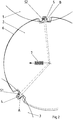
- Fig. 3 the drive gear 1 of the plate cylinder and the drive gear 3 of the printing cylinder are shown.
- the impeller 6 is arranged between the two. This is evident from the type of flank system that faces away from the drive direction.
- the idler gear 6 is arranged on a bearing block 8 fixed to the frame. Connected to the bearing block 8 in turn a bearing lever 9 is pivotally arranged.
- the bearing lever 9 can be set against the bearing block 8 by means of a clamping device 10, which contains a spring assembly and can be preloaded with a clamping screw.
- the idler gear 6 is rotatably mounted on the bearing lever 9.
- the tensioning device 10 moves the bearing lever 9 with the idler gear 6 due to its set pretension a pivot point 11 on the frame fixed bracket 8 such that it is drawn into the gap between the drive wheels 1 and 3.
- the tooth flanks facing away from the drive on the drive toothed wheels 1 and 3 come into contact with the toothing of the side gear 6 at the tooth engagements C and D.
- the drive gear 2 is arranged on a shaft journal 12 in a frame part 13.
- the idler gear 6 is arranged on bearing devices 14 coaxially with the drive gear 2.
- the bearing devices 14 are described in FIG. 5 below.
- the idler gear 6 is also connected to a bearing flange 15, which engages around the shaft journal 12 without contact on the end face.
- the bearing flange 15 is bell-shaped and carries a bearing 16 on its side used by the idler gear 6.
- the bearing 16 is in turn arranged on a collar 17 which is connected to the bearing lever 9.
- the bearing lever 9 is arranged on the bearing block 8 fixed to the frame by means of a stay bolt 18 which forms the pivot axis 11.
- the tensioning device 10 with the spring assembly engages in an eye 20.
- the idler gear can be displaced in its axial position relative to the drive gear 2 by pivoting about the bearing axis 11.
- the idler gear 6 remains freely rotatable on the bearing 16.
- Each bearing device 14 has a retaining bolt 21 fastened in the drive gear 2.
- the retaining bolt 21 extends through the idler gear 6 in openings 19.
- the openings 19 have a slightly larger diameter than the retaining bolts 21 in order to allow a relative movement between the idler gear 6 and the drive gear 2 or to enable the retaining bolt 21.
- the openings 19 can be provided in guide bushings.
- axial bearings 22 are arranged on both end faces of the idler gear 6. An axial bearing 22 is therefore arranged between the idler gear 6 and the drive gear 2 and between the screw connection 23 of the bearing pin 21 and the idler gear 6.
- the axial bearings 22 each have flat bearing disks 24 and 25, or 26 and 27 on the inner bearing disks 25, 26 can be secured against displacement by the bushings in the openings 19.
- the outer bearing disks 24, 27 are centered on shoulders of the retaining bolt 21. This allows the respective cage of the axial bearing 22 to rotate and move radially to the bearing disks 24 to 27 without the bearing being able to shift. In this way, the idler gear 6 is kept at an exactly constant distance from the drive gear 2 in all movement states.
- the device has the following functionality:
- the idler gear 6 can be permanently held in a position under the force of the tensioning device 10 via its prestressed spring assembly in which the axes of rotation of the drive gear 2 and the idler gear 6 do not overlap.
- the idler gear 6 lies on the tooth flanks opposite the driving tooth flanks of the drive gear wheels 1 and 3.
- the drive gears 1 and 3 are quasi clamped in relation to the drive gear 2.
- the relative position between the drive gear 2 and the idler gear 6 is shown in more detail in FIG. 2.
- the adjustable preload of the tensioning device 10 makes it possible to provide different auxiliary forces to compensate for drive play between the drive gear 2 and the idler gear 6. This makes it possible to influence the operating conditions of the rotary machine and the load on the drive train.
- the type of suspension of the idler gear 6 relative to the drive gear 2 is of course possible in a different way than shown in the aforementioned example.
- the idler gear 6 can also be fastened to the drive gear 2 on a linearly guided adjusting device.
- the drive clearances are relatively small, a sufficiently precise adjustment of the idler gear 6 is also possible with the aid of the bearing lever 9 mentioned, the displacement of which is not exceeded by a maximum amount due to the pivoting radius of the bearing lever 9 out of the necessary engagement space.
- the device can be arranged very compactly in the manner shown and can also be easily assembled.
- the drive gear 2 only needs to be changed slightly, so that the effort for installing the device would require greater effort.
Landscapes
- Engineering & Computer Science (AREA)
- Mechanical Engineering (AREA)
- Gear Transmission (AREA)
- Testing Of Devices, Machine Parts, Or Other Structures Thereof (AREA)
- Accessory Devices And Overall Control Thereof (AREA)
- Character Spaces And Line Spaces In Printers (AREA)
- Rotary Presses (AREA)
Applications Claiming Priority (2)
| Application Number | Priority Date | Filing Date | Title |
|---|---|---|---|
| DE19540573A DE19540573C1 (de) | 1995-10-31 | 1995-10-31 | Vorrichtung zum Spielausgleich in Rotationsdruckmaschinen |
| DE19540573 | 1995-10-31 |
Publications (2)
| Publication Number | Publication Date |
|---|---|
| EP0771648A1 true EP0771648A1 (fr) | 1997-05-07 |
| EP0771648B1 EP0771648B1 (fr) | 1998-10-21 |
Family
ID=7776282
Family Applications (1)
| Application Number | Title | Priority Date | Filing Date |
|---|---|---|---|
| EP96115260A Expired - Lifetime EP0771648B1 (fr) | 1995-10-31 | 1996-09-24 | Dispositif de rattrapage de jeu dans une machine d'impression |
Country Status (4)
| Country | Link |
|---|---|
| EP (1) | EP0771648B1 (fr) |
| JP (1) | JPH09177903A (fr) |
| AT (1) | ATE172406T1 (fr) |
| DE (2) | DE19540573C1 (fr) |
Cited By (1)
| Publication number | Priority date | Publication date | Assignee | Title |
|---|---|---|---|---|
| EP0943433A1 (fr) * | 1998-03-16 | 1999-09-22 | Grapha-Holding Ag | Unité d'impression pour une machine à imprimer, en particulier une machine rotative d'impression offset |
Families Citing this family (6)
| Publication number | Priority date | Publication date | Assignee | Title |
|---|---|---|---|---|
| DE19716283A1 (de) * | 1997-04-18 | 1998-10-22 | Koenig & Bauer Albert Ag | Zylinderanordnung für Rollenrotationsdruckmaschinen |
| US6335392B1 (en) | 1998-10-21 | 2002-01-01 | Sumitomo Rubber Industries, Ltd. | Outsole of shoes |
| DE10023682A1 (de) * | 2000-05-16 | 2001-11-22 | Roland Man Druckmasch | Antrieb eines Anlegers für eine Bogen verarbeitende Maschine |
| DE102007020225A1 (de) * | 2007-04-28 | 2008-10-30 | Koenig & Bauer Aktiengesellschaft | Vorrichtung zur Synchronisierung der Drehbewegung von einzeln angetriebenen Rotationskörpern |
| DE102007025752A1 (de) * | 2007-06-01 | 2008-12-04 | Manroland Ag | Angetriebene Baugruppe einer Druckmaschine |
| DE102009057849A1 (de) | 2009-12-10 | 2011-06-16 | Heidelberger Druckmaschinen Ag | Offsetdruckmaschine |
Citations (3)
| Publication number | Priority date | Publication date | Assignee | Title |
|---|---|---|---|---|
| US3407727A (en) * | 1966-03-23 | 1968-10-29 | Maschf Augsburg Nuernberg Ag | Supplementary driving gear arrangement for multi-color sheet-fed rotary printing presses |
| GB1135164A (en) * | 1966-04-16 | 1968-12-04 | Albert Schnellpressen | Improvements in or relating to drive mechanisms for the printing mechanisms of rotary printing presses |
| GB1214422A (en) * | 1968-04-20 | 1970-12-02 | Maschf Augsburg Nuernberg Ag | Improvements in or relating to rotary offset printing machines |
Family Cites Families (3)
| Publication number | Priority date | Publication date | Assignee | Title |
|---|---|---|---|---|
| JPS4831470B1 (fr) * | 1970-05-26 | 1973-09-29 | ||
| DE8109324U1 (de) * | 1981-03-30 | 1983-03-10 | M.A.N.- Roland Druckmaschinen AG, 6050 Offenbach | Spielfreier Zahnradtrieb für Druckmaschinen |
| JPS5881263A (ja) * | 1981-10-30 | 1983-05-16 | ゼロツクス・コ−ポレ−シヨン | 対向ばね式バツクラツシ防止分割歯車 |
-
1995
- 1995-10-31 DE DE19540573A patent/DE19540573C1/de not_active Expired - Fee Related
-
1996
- 1996-09-24 DE DE59600701T patent/DE59600701D1/de not_active Expired - Fee Related
- 1996-09-24 EP EP96115260A patent/EP0771648B1/fr not_active Expired - Lifetime
- 1996-09-24 AT AT96115260T patent/ATE172406T1/de not_active IP Right Cessation
- 1996-10-30 JP JP8288760A patent/JPH09177903A/ja active Pending
Patent Citations (3)
| Publication number | Priority date | Publication date | Assignee | Title |
|---|---|---|---|---|
| US3407727A (en) * | 1966-03-23 | 1968-10-29 | Maschf Augsburg Nuernberg Ag | Supplementary driving gear arrangement for multi-color sheet-fed rotary printing presses |
| GB1135164A (en) * | 1966-04-16 | 1968-12-04 | Albert Schnellpressen | Improvements in or relating to drive mechanisms for the printing mechanisms of rotary printing presses |
| GB1214422A (en) * | 1968-04-20 | 1970-12-02 | Maschf Augsburg Nuernberg Ag | Improvements in or relating to rotary offset printing machines |
Cited By (2)
| Publication number | Priority date | Publication date | Assignee | Title |
|---|---|---|---|---|
| EP0943433A1 (fr) * | 1998-03-16 | 1999-09-22 | Grapha-Holding Ag | Unité d'impression pour une machine à imprimer, en particulier une machine rotative d'impression offset |
| US6314881B1 (en) | 1998-03-16 | 2001-11-13 | Grapha-Holding Ag | Printing group for a printing press |
Also Published As
| Publication number | Publication date |
|---|---|
| DE59600701D1 (de) | 1998-11-26 |
| ATE172406T1 (de) | 1998-11-15 |
| EP0771648B1 (fr) | 1998-10-21 |
| JPH09177903A (ja) | 1997-07-11 |
| DE19540573C1 (de) | 1996-11-07 |
Similar Documents
| Publication | Publication Date | Title |
|---|---|---|
| DE69810512T2 (de) | Modulare betätigungsvorrichtung, sowie bremssattel mit einer solchen betätigungsvorrichtung | |
| DE69515050T2 (de) | Bremssattel | |
| DE1951427C3 (de) | Ins Langsame übersetzendes Getriebe | |
| DE19614397C2 (de) | Antrieb mit Registervorrichtung für eine Druckeinheit einer Rollenrotationsdruckmaschine | |
| WO2001087605A1 (fr) | Organe d'entrainement d'un composant rotatif faisant partie d'une machine a imprimer et procede pour separer cet organe d'entrainement | |
| DE102008046792A1 (de) | Druckmaschine mit Schmitzringen | |
| EP0425936A2 (fr) | Dispositif pour le repérage, la fixation et la tension rapides de plaques d'impression | |
| DE19715026B4 (de) | Elastischer Antrieb für Druckmaschinen | |
| DE19540573C1 (de) | Vorrichtung zum Spielausgleich in Rotationsdruckmaschinen | |
| DE4012965C1 (de) | Vorrichtung zum An-, Ab- und Einstellen von Auftragwalzen | |
| EP1310360A2 (fr) | Machine d'impression flexographique avec des cylindres de transfert d'encre applicables de façon manuelle et automatique | |
| DE2829895C2 (de) | Winkelgetriebe für eine Fahrzeuglenkung | |
| EP0683043B1 (fr) | Cylindre d'impression d'une machine d'impression rotative | |
| DE4430625B4 (de) | Lagereinheit für eine Walzenanordnung | |
| EP0172412A2 (fr) | Cylindre de transfert de feuilles dans les rotatives d'impression de feuilles | |
| DE3317746C2 (de) | Druckwerk und Verfahren zum Drucken | |
| DE2452650B1 (de) | Freilaufkupplung mit unrunden Klemmkoerpern | |
| CH687244A5 (de) | Vorrichtung zum Verfahren von zwei auf Schlitten befestigten Lagerboecken. | |
| DE2921153A1 (de) | Vorrichtung zum einstellen des seiten- und umfangsregisters in rotationsdruckmaschinen | |
| DE4447862C2 (de) | Einrichtung zur Getriebezugtrennung | |
| EP1984181B1 (fr) | Couplage de cylindre gravé | |
| DE102008023333A1 (de) | Übertragungstrommel zum Fördern eines Bogens in einer drucktechnischen Maschine | |
| DE60005496T2 (de) | Differentialsperre | |
| DE4436584C2 (de) | Plattenzylinderlagerung | |
| EP0508113A1 (fr) | Dispositif pour serrer rapidement et précisément et tendre des clichés sur le cylindre porte-plaque d'une machine à imprimer |
Legal Events
| Date | Code | Title | Description |
|---|---|---|---|
| PUAI | Public reference made under article 153(3) epc to a published international application that has entered the european phase |
Free format text: ORIGINAL CODE: 0009012 |
|
| 17P | Request for examination filed |
Effective date: 19961009 |
|
| AK | Designated contracting states |
Kind code of ref document: A1 Designated state(s): AT CH DE FR GB IT LI NL |
|
| GRAG | Despatch of communication of intention to grant |
Free format text: ORIGINAL CODE: EPIDOS AGRA |
|
| GRAG | Despatch of communication of intention to grant |
Free format text: ORIGINAL CODE: EPIDOS AGRA |
|
| GRAH | Despatch of communication of intention to grant a patent |
Free format text: ORIGINAL CODE: EPIDOS IGRA |
|
| 17Q | First examination report despatched |
Effective date: 19980121 |
|
| GRAH | Despatch of communication of intention to grant a patent |
Free format text: ORIGINAL CODE: EPIDOS IGRA |
|
| GRAA | (expected) grant |
Free format text: ORIGINAL CODE: 0009210 |
|
| AK | Designated contracting states |
Kind code of ref document: B1 Designated state(s): AT CH DE FR GB IT LI NL |
|
| PG25 | Lapsed in a contracting state [announced via postgrant information from national office to epo] |
Ref country code: NL Free format text: LAPSE BECAUSE OF FAILURE TO SUBMIT A TRANSLATION OF THE DESCRIPTION OR TO PAY THE FEE WITHIN THE PRESCRIBED TIME-LIMIT Effective date: 19981021 Ref country code: IT Free format text: LAPSE BECAUSE OF FAILURE TO SUBMIT A TRANSLATION OF THE DESCRIPTION OR TO PAY THE FEE WITHIN THE PRESCRIBED TIME-LIMIT;WARNING: LAPSES OF ITALIAN PATENTS WITH EFFECTIVE DATE BEFORE 2007 MAY HAVE OCCURRED AT ANY TIME BEFORE 2007. THE CORRECT EFFECTIVE DATE MAY BE DIFFERENT FROM THE ONE RECORDED. Effective date: 19981021 |
|
| REF | Corresponds to: |
Ref document number: 172406 Country of ref document: AT Date of ref document: 19981115 Kind code of ref document: T |
|
| REG | Reference to a national code |
Ref country code: CH Ref legal event code: NV Representative=s name: E. BLUM & CO. PATENTANWAELTE Ref country code: CH Ref legal event code: EP |
|
| GBT | Gb: translation of ep patent filed (gb section 77(6)(a)/1977) |
Effective date: 19981022 |
|
| ET | Fr: translation filed | ||
| REF | Corresponds to: |
Ref document number: 59600701 Country of ref document: DE Date of ref document: 19981126 |
|
| NLV1 | Nl: lapsed or annulled due to failure to fulfill the requirements of art. 29p and 29m of the patents act | ||
| PLBE | No opposition filed within time limit |
Free format text: ORIGINAL CODE: 0009261 |
|
| STAA | Information on the status of an ep patent application or granted ep patent |
Free format text: STATUS: NO OPPOSITION FILED WITHIN TIME LIMIT |
|
| 26N | No opposition filed | ||
| PGFP | Annual fee paid to national office [announced via postgrant information from national office to epo] |
Ref country code: GB Payment date: 20010814 Year of fee payment: 6 |
|
| PGFP | Annual fee paid to national office [announced via postgrant information from national office to epo] |
Ref country code: CH Payment date: 20010816 Year of fee payment: 6 |
|
| PGFP | Annual fee paid to national office [announced via postgrant information from national office to epo] |
Ref country code: AT Payment date: 20010824 Year of fee payment: 6 |
|
| PGFP | Annual fee paid to national office [announced via postgrant information from national office to epo] |
Ref country code: FR Payment date: 20010904 Year of fee payment: 6 |
|
| REG | Reference to a national code |
Ref country code: GB Ref legal event code: IF02 |
|
| PG25 | Lapsed in a contracting state [announced via postgrant information from national office to epo] |
Ref country code: GB Free format text: LAPSE BECAUSE OF NON-PAYMENT OF DUE FEES Effective date: 20020924 Ref country code: AT Free format text: LAPSE BECAUSE OF NON-PAYMENT OF DUE FEES Effective date: 20020924 |
|
| PG25 | Lapsed in a contracting state [announced via postgrant information from national office to epo] |
Ref country code: LI Free format text: LAPSE BECAUSE OF NON-PAYMENT OF DUE FEES Effective date: 20020930 Ref country code: CH Free format text: LAPSE BECAUSE OF NON-PAYMENT OF DUE FEES Effective date: 20020930 |
|
| GBPC | Gb: european patent ceased through non-payment of renewal fee |
Effective date: 20020924 |
|
| REG | Reference to a national code |
Ref country code: CH Ref legal event code: PL |
|
| PG25 | Lapsed in a contracting state [announced via postgrant information from national office to epo] |
Ref country code: FR Free format text: LAPSE BECAUSE OF NON-PAYMENT OF DUE FEES Effective date: 20030603 |
|
| REG | Reference to a national code |
Ref country code: FR Ref legal event code: ST |
|
| PGFP | Annual fee paid to national office [announced via postgrant information from national office to epo] |
Ref country code: DE Payment date: 20050912 Year of fee payment: 10 |
|
| PG25 | Lapsed in a contracting state [announced via postgrant information from national office to epo] |
Ref country code: DE Free format text: LAPSE BECAUSE OF NON-PAYMENT OF DUE FEES Effective date: 20070403 |