EP0771709B1 - Détecteur de déplacement dans un appareil de transfert et contrôleur d'entraínement de l'élément de transfert - Google Patents
Détecteur de déplacement dans un appareil de transfert et contrôleur d'entraínement de l'élément de transfert Download PDFInfo
- Publication number
- EP0771709B1 EP0771709B1 EP96120360A EP96120360A EP0771709B1 EP 0771709 B1 EP0771709 B1 EP 0771709B1 EP 96120360 A EP96120360 A EP 96120360A EP 96120360 A EP96120360 A EP 96120360A EP 0771709 B1 EP0771709 B1 EP 0771709B1
- Authority
- EP
- European Patent Office
- Prior art keywords
- displacement
- pulley
- wire rope
- side coil
- coil
- Prior art date
- Legal status (The legal status is an assumption and is not a legal conclusion. Google has not performed a legal analysis and makes no representation as to the accuracy of the status listed.)
- Expired - Lifetime
Links
- 238000006073 displacement reaction Methods 0.000 title claims description 69
- 239000000126 substance Substances 0.000 claims description 3
- 239000000969 carrier Substances 0.000 description 9
- 230000002093 peripheral effect Effects 0.000 description 4
- 239000003990 capacitor Substances 0.000 description 2
- 238000010276 construction Methods 0.000 description 2
- 238000010586 diagram Methods 0.000 description 2
- 230000004907 flux Effects 0.000 description 2
- 238000009499 grossing Methods 0.000 description 2
- 238000006243 chemical reaction Methods 0.000 description 1
- 230000007547 defect Effects 0.000 description 1
- 238000001514 detection method Methods 0.000 description 1
- 230000006698 induction Effects 0.000 description 1
- 230000005389 magnetism Effects 0.000 description 1
- 238000012544 monitoring process Methods 0.000 description 1
Images


Classifications
-
- B—PERFORMING OPERATIONS; TRANSPORTING
- B61—RAILWAYS
- B61B—RAILWAY SYSTEMS; EQUIPMENT THEREFOR NOT OTHERWISE PROVIDED FOR
- B61B12/00—Component parts, details or accessories not provided for in groups B61B7/00 - B61B11/00
- B61B12/06—Safety devices or measures against cable fracture
-
- B—PERFORMING OPERATIONS; TRANSPORTING
- B61—RAILWAYS
- B61B—RAILWAY SYSTEMS; EQUIPMENT THEREFOR NOT OTHERWISE PROVIDED FOR
- B61B12/00—Component parts, details or accessories not provided for in groups B61B7/00 - B61B11/00
- B61B12/02—Suspension of the load; Guiding means, e.g. wheels; Attaching traction cables
Definitions
- This invention relates to a displacement detector of a rope against a guide member for detecting a displacement degree when the rope guided by a guide member such as a pulley is displaced from a standard point set in the guide member, and to a drive control device of a transfer member for controlling a driving speed by means of the displacement detector.
- a transfer apparatus having a rope guided by a guide member includes, for example, a lift device, car gondola device, ropeway, and cable car (hereinafter referred to as the lift device) which consist of pulleys and wire ropes, and what is generally known is a ski lift which is disposed at skiing grounds.
- the lift device because of its structure, carriers suspended from the wire rope have a drawback of being easily influence by a side wind with resect to the moving direction of the carriers.
- the ski lift is disposed among the mountains where a gust of wind blows, there is a danger that the wire rope easily comes off the pulley because of the sway of the carriers from side to side due to a side wind.
- an off-position detector is disposed on each lift device to detect the off-position of the wire rope from a pulley on one hand, and a monitor camera is used to monitor the sideward sway of the carriers on the other hand.
- the above off-position detector detects the off-position of the wire rope from a pulley when the wire rope displaced from the pulley presses a switch such as a limit switch which is disposed on the side of the pulley. And, to monitor the sideward sway of carriers with the monitor camera, monitor cameras are disposed at a plurality of places along the stretched direction of the wire rope, and a man keeps observing the sideward sway of carriers due to wind on monitors from the cameras.
- the pulley In the lift device, the pulley is generally fixed and the wire rope is designed to travel, but there is a lift device where the wire rope is conversely fixed and the pulley travels, and there is a danger in the same way as above that the pulley is easily displaced from the wire rope because of a sideward swat of the carrier due to a side wind.
- the wire rope travels.
- the aforementioned conventional off-position detector is aimed at preventing a secondary hazard which may be caused by operating the lift with the wire roped displaced from a pulley, and has a problem that it cannot prevent the off-position of the wire rope from the pulley. And, monitoring of the sideward sway of carriers through the monitor cameras can hardly prevent the wire rope from coming off of the pulley groove due to a gust of wind. Further, the recent ski lift is operated at a high speed and the number of lifts carrying a plurality of passengers are increasing, and a gondola and ropeway are enlarging in size, and accordingly the possibility of off-position of the wire rope from the pulley is increasing, leading to the increase of injured people due to accidents every year.
- this invention aims to provide a displacement detector of a metallic rope against a guide member which detects a displacement degree of a wire rope from a guide member, so that the off-position of the rope from the pulley can be prevented automatically efficiently, and which can be easily installed to existing lift facilities; and also aims to provide a drive control device of the transfer member which detects a displacement degree of a rope from a standard position in a pulley groove at a plurality of points, controls an operating speed of the transfer member according to each displacement degree to prevent the off-position of the rope from the pulley groove automatically and efficiently, improves the safety and carrying capacity of the lift substantially, and can be easily disposed on exiting lift facilities.
- the invention provides a displacement detector for a wire rope made of a magnetic substance, said displacement detector being provided in a transport apparatus having a pulley engaging with said wire rope and a transport unit traveling together with said wire rope or said pulley, and said detector being designed to detect a relative position between the wire rope and the pulley, comprising: displacement detecting coils disposed at an equal interval of one side face of the pulley and electrically connected in series, a revolving side coil disposed on the pulley and connected to the end of the displacement detecting coils connected in series, a stationary side coils disposed opposite of the revolving side coil, and forming a transformer together with the revolving side coil by being applied with a DC voltage, and a detecting means connected to both ends of the stationery side coil for detecting an impedance change generated in the displacement detecting coils.
- a displacement degree of the rope particularly a displacement degree from a standard position when displaced from an optional position as a standard can be detected by a simple structure, so that the off-position of the rope such as a wire rope from the guide member such as a pulley can be prevented automatically and efficiently by disposing the detector at a prescribed position.
- this invention provides a speed control means to drive the transfer member to the displacement detector, and this speed control means is a drive control device of the transfer member for controlling a speed of the transfer member according to an output signal of a displacement degree from the displacement detector.
- this speed control means is a drive control device of the transfer member for controlling a speed of the transfer member according to an output signal of a displacement degree from the displacement detector.
- a displacement degree of the rope from the standard point determined within the guide member is detected by the displacement detector, and according to the displacement degree, the operating speed of the transfer member is synthetically controlled according to the displacement degree so as to be able to prevent the rope from being displaced from the guide member automatically and efficiently, improving the safety and carrying capacity of the transfer member substantially.
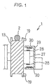
- Fig. 1 is a sectional view showing the displacement detector according to an eleventh embodiment.
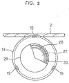
- Fig. 2 is a side view showing the above displacement detector.
- Fig. 3 is a circuit diagram showing the above displacement detector.
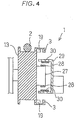
- Fig. 4 is a sectional view showing the displacement detector according to a twelfth embodiment.
- Fig. 5 is a circuit diagram of the above displacement detector.
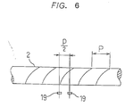
- Fig. 6 is a view showing the detection unit corresponding to a lay of the wire rope according to a seventh embodiment.
- the displacement detector of a rope according to the invention detects a displacement degree of a wire rope with respect to a guide member according to an output voltage from a magnetoelectric conversion means which is disposed in a magnetic circuit formed by a magnet and a wire rope wherein the magnet is disposed to face the wire rope which is made of a magnetic substance to form the rope.
- magnetism is used as a medium for detecting a position emitted from the detector toward the rope.
- the displacement detector 1 according to an embodiment shown in Fig. 1 and Fig. 2 comprises a pulley 13, displacement detecting coils 19, a revolving part 27, a revolving side coil 28, a stationary part 29, a stationary side coil 30, a detecting part 35, a rectifying part 34, and a differential amplifying part 6.
- the above displacement detecting coils 19 are disposed at an equal interval in the peripheral direction on one side of the pulley 13 as shown in Fig. 2, and each displacement detecting coil is connected to the detecting part 35 via a rotary transformer 31 which consists of the stationary side coil 30 and the revolving side coil 28, to be described afterward, mutually connected in series on the circuit as shown in Fig. 3. In this embodiment, they are disposed at three points at an equal interval in the peripheral direction, but may be disposed in more numbers.
- the above revolving part 27 is a small projected part formed coaxially with the pulley 13 on one side of the pulley 13, and the above revolving side coil 28 is wound in certain turns on the outer periphery of the revolving part 27.
- the above stationary part 29 is formed in the shape of a cylinder which has a larger diameter than the revolving 27 and whose one end is closed, and the above stationary side coil 30 is wound in certain turns on the inner periphery of the stationary part 29.
- the above detecting part 35 comprises the oscillator 37 which is connect in parallel to the above stationary side coil 30 as shown in Fig. 3.
- the above stationary side coil 30 has a high-frequency signal applied by the oscillator 37, and when the wire rope 2 is displaced from the standard position of displacement to approach to the displacement detecting coil 19, mutual induction is caused between the wire rope 2 and each displacement detecting coil 19, causing an impedance change in each displacement detecting coil 19.
- a voltage which is applied between both ends of the displacement detecting coil 19 at this time is applied with its voltage changed to both ends of the above stationary side coil 30 via the above rotary transformer 31.
- the above rectifying part 34 is connected to both ends of the stationary side coil 30, and a voltage signal which is applied between both ends of the stationary side coil 30 is rectified into a DC voltage signal by the smoothing circuit consisting of the diode 32 and the capacitor 33.
- the above differential amplifying part 6 is a common differential amplifying circuit which comprises an operation amplifier 38 whose plus and minus terminals on the input side are connected with two output lines from the above rectifying part 34, and a deviation of the DC voltage signal outputted between both output lines is amplified to a certain level and obtained as a displacement degree.
- the AC signal by the oscillator 37 is applied to the displacement detecting coil 19 via the rotary transformer 31 consisting of the stationary side coil 30 and the revolving side coil 28, falling in a state supplied.
- the impedance of the displacement detecting coil 19 is changed.
- a voltage applied to both ends of the displacement detecting coil 19 is changed, the changed voltage is rectified into a DC voltage in the rectifying part 34 via the rotary transformer 31, and then amplified to a certain level in the differential amplifying part 6 to obtain a displacement degree.
- the application of the AC signal to the displacement detecting coil 19 and the detecting of the impedance change of the displacement detecting coil 19 can be made without contacting to the pulley 13.
- the displacement detector 1 of a twelfth embodiment shown in Fig. 4 comprises displacement detecting coils 19, magnets 3, a revolving part 27, a revolving side coil 28, a stationary part 29, a stationary side coil 30, a rectifying part 34, and a differential amplifying part 6.
- the above displacement detecting coils 19 are disposed at an equal interval in the peripheral direction on one side of the pulley 13, and each displacement detecting coil 19 is connected in series as shown in Fig. 4. As shown in Fig. 24, both ends of the displacement detecting coil 19 connected in series are connected to the rectifying part 34 via the rotary transformer 31 consisting of the revolving side coil 28 and the stationary side coil 30 to be described afterward. In this embodiment, they are disposed at three points at an equal interval in the peripheral direction.
- the above magnets 3 are disposed apart from the displacement detecting coil 19 on the back of the above displacement detecting coil 19 far from the pulley's groove as shown in Fig. 4. These magnets 3 are to form magnetic flux B which is generated from N pole and passes across the wire rope 2.
- the above revolving part 27 is a small projected part formed coaxially with the pulley 13 on one side of the pulley 13, and the above revolving side coil 28 is wound in certain turns on the outer periphery of the revolving part 27.
- the above stationary part 29 is formed in the shape of a cylinder which has a larger diameter than the revolving 27 and whose one end is closed, and the above stationary side coil 30 is wound in certain turns on the inner periphery of the stationary part 29.
- the above rectifying part 34 is connected to both ends of the stationary side coil 30 as shown in Fig. 5, and a voltage signal due to an induced electromotive force generated in the above revolving side coil 28 is rectified into a DC voltage signal by the smoothing circuit consisting of the diode 32,and the capacitor 33.
- the above differential amplifying part 6 is a common differential amplifying circuit which comprises an operation amplifier 38 whose plus and minus terminals on the input side are connected with two output lines from the above rectifying part 34 as shown in Fig. 5, and a deviation of the DC voltage signal outputted between both output lines is amplified to a certain level and obtained as a displacement degree.
- the displacement detector 1 is a detector using a strand such as the wire rope 2 as the metallic rope in the same way as in the seventh embodiment.
- two sets of coils 19 and the magnet 3 are disposed in parallel with an interval of 1/2 of pitch P of the lay along the axial direction of the wire rope 2 as shown in Fig. 6, and the output voltage from each coil 19 is synthesized, so that the ripple component can be removed from the output voltage.
- the output voltage having a phase inverted by 180 degrees from each coil 19 is obtained, and by adding each output voltage, the ripple component can be removed, so that without being influenced by the lay of the wire rope 2, a displacement degree can be detected at high accuracy.
Landscapes
- Engineering & Computer Science (AREA)
- Transportation (AREA)
- Mechanical Engineering (AREA)
- Measurement Of Length, Angles, Or The Like Using Electric Or Magnetic Means (AREA)
- Control And Safety Of Cranes (AREA)
- Control Of Position Or Direction (AREA)
Claims (3)
- Détecteur de déplacement pour un câble métallique (2) constitué d'une substance magnétique, ledit détecteur de déplacement étant disposé dans un appareil de transport ayant une poulie (13) mettant en prise ledit câble métallique (2) et une unité de transport se déplaçant avec ledit câble métallique (2) ou avec ladite poulie (13), et ledit détecteur étant conçu pour détecter une position relative entre le câble métallique (2) et la poulie (13), comprenant :des bobines de détection de déplacement (19) disposées à un intervalle égal d'une face latérale de la poulie (13) et électriquement connectées en série,une bobine latérale rotative (28) disposée sur la poulie (13) et connectée à l'extrémité des bobines de détection de déplacement (19) connectées en série,une bobine latérale immobile (30) disposée opposée à la bobine latérale rotative (28) et formant un transformateur (31) avec la bobine latérale rotative (28) en recevant une tension continue, etun moyen de détection (35) connecté aux deux extrémités de la bobine latérale immobile (30) pour détecter un changement d'impédance produit dans les bobines de détection de déplacement (19).
- Détecteur de déplacement selon la revendication 1, caractérisé en ce que ledit moyen de détection (35) comprend un oscillateur (37) connecté en parallèle à ladite bobine latérale immobile (30) pour appliquer un signal de haute fréquence à ladite bobine latérale immobile (30).
- Détecteur de déplacement selon la revendication 1,
caractérisé par des aimants (3) disposés sur la façade arrière des bobines de détection de déplacement (19) du même nombre que les bobines de détection de déplacement (19).
Applications Claiming Priority (7)
| Application Number | Priority Date | Filing Date | Title |
|---|---|---|---|
| JP31619491 | 1991-11-29 | ||
| JP31619491 | 1991-11-29 | ||
| JP316194/91 | 1991-11-29 | ||
| JP31724691 | 1991-12-02 | ||
| JP31724691 | 1991-12-02 | ||
| JP317246/91 | 1991-12-02 | ||
| EP92924025A EP0613807B1 (fr) | 1991-11-29 | 1992-11-27 | Deplacement dans un appareil de transfert et controleur d'entrainement de l'element de transfert |
Related Parent Applications (2)
| Application Number | Title | Priority Date | Filing Date |
|---|---|---|---|
| EP92924025A Division EP0613807B1 (fr) | 1991-11-29 | 1992-11-27 | Deplacement dans un appareil de transfert et controleur d'entrainement de l'element de transfert |
| EP92924025.7 Division | 1993-06-21 |
Publications (2)
| Publication Number | Publication Date |
|---|---|
| EP0771709A1 EP0771709A1 (fr) | 1997-05-07 |
| EP0771709B1 true EP0771709B1 (fr) | 2000-08-23 |
Family
ID=26568578
Family Applications (2)
| Application Number | Title | Priority Date | Filing Date |
|---|---|---|---|
| EP92924025A Expired - Lifetime EP0613807B1 (fr) | 1991-11-29 | 1992-11-27 | Deplacement dans un appareil de transfert et controleur d'entrainement de l'element de transfert |
| EP96120360A Expired - Lifetime EP0771709B1 (fr) | 1991-11-29 | 1992-11-27 | Détecteur de déplacement dans un appareil de transfert et contrôleur d'entraínement de l'élément de transfert |
Family Applications Before (1)
| Application Number | Title | Priority Date | Filing Date |
|---|---|---|---|
| EP92924025A Expired - Lifetime EP0613807B1 (fr) | 1991-11-29 | 1992-11-27 | Deplacement dans un appareil de transfert et controleur d'entrainement de l'element de transfert |
Country Status (4)
| Country | Link |
|---|---|
| US (1) | US5581180A (fr) |
| EP (2) | EP0613807B1 (fr) |
| DE (2) | DE69231388T2 (fr) |
| WO (1) | WO1993011015A1 (fr) |
Cited By (1)
| Publication number | Priority date | Publication date | Assignee | Title |
|---|---|---|---|---|
| RU2493989C2 (ru) * | 2008-03-13 | 2013-09-27 | Хима Пауль Хильдебрандт Гмбх + Ко Кг | Система контроля износа, транспортная установка с канатным приводом и способ контроля быстроизнашивающихся деталей такой транспортной установки |
Families Citing this family (37)
| Publication number | Priority date | Publication date | Assignee | Title |
|---|---|---|---|---|
| DE19752362A1 (de) * | 1997-11-26 | 1999-06-17 | Doppelmayr Seilbahn Produktion | Schaltungsanordnung zur Überwachung des fehlerfreien und/oder zur Erkennung eines fehlerbehafteten Zustands einer Anlage |
| US6222899B1 (en) | 1998-07-30 | 2001-04-24 | The United States Of America As Represented By The Secretary Of The Navy | System for determining the deployed length of a flexible tension element |
| US6241462B1 (en) | 1999-07-20 | 2001-06-05 | Collaborative Motion Control, Inc. | Method and apparatus for a high-performance hoist |
| JP4556374B2 (ja) * | 1999-12-14 | 2010-10-06 | パナソニック株式会社 | 非接触型位置センサ |
| US6267205B1 (en) * | 2000-04-18 | 2001-07-31 | Otis Elevator Company | Magnetic guidance for an elevator rope |
| ITBZ20030005A1 (it) | 2003-01-30 | 2004-07-31 | High Technology Invest Bv | Dispositivo pressore per la conduzione di fune in sistemi di trasporto a trazione di fune. |
| DE602004026260D1 (de) * | 2003-11-06 | 2010-05-12 | Optosys Ag | Kabelpositionssensor |
| US7313259B2 (en) * | 2003-11-26 | 2007-12-25 | General Electric Company | Method, system and computer program product for multi-modality registration using virtual cursors |
| ITBZ20050051A1 (it) | 2005-09-29 | 2007-03-30 | High Technology Invest Bv | Dispositivo antiscarrucolamento per funi di impianti funiviari. |
| DE102007006316B3 (de) * | 2007-01-30 | 2008-04-10 | Hima Paul Hildebrandt Gmbh + Co Kg | Vorrichtung und Verfahren zur Seillageüberwachung einer seilbetriebenen Transportanlage und seilbetriebene Transportanlage |
| ITMI20070157U1 (it) | 2007-04-20 | 2008-10-21 | Rolic Invest Sarl | Seggiovia |
| ITMI20070835A1 (it) | 2007-04-20 | 2008-10-21 | Rolic Invest Sarl | Impianto di trasporto a fune e metodo di azionamento dello stesso |
| ITMI20071618A1 (it) | 2007-08-03 | 2009-02-04 | Rolic Invest Sarl | Impianto di trasporto a fune e metodo di azionamento dello stesso |
| FR2919841A1 (fr) | 2007-08-10 | 2009-02-13 | Pomagalski Sa | Dispositif de guidage d'un cable aerien d'une installation de remontee mecanique comportant des moyens d'arret automatique de l'installation |
| ITMI20072071A1 (it) | 2007-10-26 | 2009-04-27 | Rolic Invest Sarl | Impianto di trasporto a fune e metodo di azionamento dello stesso |
| US7764169B2 (en) * | 2008-03-12 | 2010-07-27 | Eaton Corporation | System for monitoring a plurality of sensors |
| IT1395098B1 (it) | 2009-07-09 | 2012-09-05 | Rolic Invest Sarl | Unita' di trasporto per impianti di trasporto a fune |
| IT1395737B1 (it) | 2009-08-04 | 2012-10-19 | Rolic Invest Sarl | Dispostivo di richiamo di un sedile per skilift |
| FR2951681B1 (fr) * | 2009-10-23 | 2011-12-02 | Gimar Montaz Mautino | Dispositif de surveillance de rotation d'un organe tournant d'appui et de guidage, dans une installation de remontee mecanique |
| CN101716939B (zh) * | 2009-12-26 | 2011-08-24 | 枣庄矿业(集团)有限责任公司柴里煤矿 | 架空乘人装置钢丝绳脱槽落地保护装置 |
| IT1401120B1 (it) | 2010-07-14 | 2013-07-12 | Rolic Invest Sarl | Scambio per impianto di trasporto a fune e impianto di trasporto a fune comprendente tale scambio. |
| GB201108398D0 (en) * | 2011-05-19 | 2011-07-06 | Loach Andrew | Hand-held exercise apparatus and resistance mechanism for exercise apparatus |
| AT512298B1 (de) * | 2012-02-06 | 2013-07-15 | Innova Patent Gmbh | Rolle, insbesondere laufrolle bzw. tragrolle für seilbahnanlagen |
| US10046815B2 (en) | 2012-03-27 | 2018-08-14 | Wearpro Incorporated | Wear monitoring device and method of monitoring undercarriage and roller wear |
| EP2789985A1 (fr) * | 2013-04-10 | 2014-10-15 | Tyco Electronics AMP GmbH | Capteur de position sans contact et système de capteur de position sans contact |
| CN107879232B (zh) * | 2016-09-30 | 2021-07-20 | 奥的斯电梯公司 | 补偿链稳定装置和方法,电梯井道以及电梯系统 |
| EP3336033A1 (fr) * | 2016-12-19 | 2018-06-20 | KONE Corporation | Agencement d'un dispositif de levage |
| EP3375686A1 (fr) | 2017-03-16 | 2018-09-19 | Bartholet Maschinenbau AG | Dispositif et procédé de surveillance d'une télécabine |
| RU2735380C1 (ru) * | 2017-08-25 | 2020-10-30 | Иннова Патент Гмбх | Индуктивный сенсор |
| CN109295951B (zh) * | 2018-10-15 | 2024-07-16 | 煤炭科学技术研究院有限公司 | 分段架线式边坡地表变形自动监测系统 |
| FR3093490B1 (fr) * | 2019-03-05 | 2021-03-12 | Poma | Installation de transport de véhicule par câble et procédé de mesure d’une information concernant une telle installation |
| JP2020169917A (ja) * | 2019-04-04 | 2020-10-15 | 日本電産株式会社 | 信号処理回路、モータの駆動システム |
| AT522584B1 (de) * | 2019-05-28 | 2020-12-15 | Innova Patent Gmbh | Verfahren zum Erfassen eines Verschleißes einer Seilrolle einer Seilbahnanlage |
| FR3118934B1 (fr) * | 2021-01-15 | 2023-09-01 | Poma | Installation de transport par câble à sécurité améliorée, procédé de détection d’un événement sur câble et procédé de réalisation d’une telle installation |
| JP2023180625A (ja) * | 2022-06-10 | 2023-12-21 | 日本ケーブル株式会社 | 索条のスプライス部検出装置 |
| AT527772A1 (de) * | 2023-11-15 | 2025-06-15 | Innova Patent Gmbh | Anordnung zur Überwachung einer Lagerung einer Rollenbatterie |
| CN121361071B (zh) * | 2025-11-05 | 2026-05-01 | 北京邮电大学 | 一种基于分布式磁感应的多模态感知腱绳系统及其测量方法 |
Family Cites Families (19)
| Publication number | Priority date | Publication date | Assignee | Title |
|---|---|---|---|---|
| US2452156A (en) * | 1945-09-24 | 1948-10-26 | Donald S Schover | Float position indicator |
| CH393144A (de) * | 1960-07-07 | 1965-05-31 | Siemens Ag | Magnetisch-elektrischer Signalgeber |
| CH421169A (de) * | 1964-07-10 | 1966-09-30 | Walter Staedeli Maschinenbau | Uberwachungsverfahren des Entgleisens eines Stahldrahtseiles einer Seilbahnanlage und Gerät zur Ausübung dieses Verfahrens |
| US3991413A (en) * | 1975-06-23 | 1976-11-09 | Berger Philip H | Constant current detector system |
| US4271763A (en) * | 1978-05-15 | 1981-06-09 | Berger Philip H | Proximity detector |
| JPS55138602A (en) * | 1979-04-17 | 1980-10-29 | Meiki Denki Seisakusho:Kk | Detection of wire rope position |
| JPS6041806U (ja) * | 1983-08-29 | 1985-03-25 | 日産自動車株式会社 | 変位量検出装置 |
| US4671187A (en) * | 1985-09-20 | 1987-06-09 | Kunczynski Jan K | Deropement sensor apparatus with gravity-biased, falling, magnetic member |
| JPS6295977U (fr) * | 1985-12-09 | 1987-06-18 | ||
| JPS62204118A (ja) * | 1986-03-05 | 1987-09-08 | Hitachi Ltd | 磁気的に位置あるいは速度を検出する装置 |
| JPS6430027A (en) * | 1987-07-27 | 1989-01-31 | Mitsubishi Electric Corp | Optical head |
| DE3740800A1 (de) * | 1987-12-02 | 1989-06-15 | Bosch Gmbh Robert | Vorrichtung zur erfassung des wegs oder des drehwinkels |
| AT388146B (de) * | 1988-01-08 | 1989-05-10 | Engel Edwin Dipl Ing Dr Techn | Verfahren und vorrichtungen zur selbsttaetigen ueberwachung der lage der foerderseile von seilbahnen und schleppliften auf einer seiltragrolle |
| JPH0219712A (ja) * | 1988-07-07 | 1990-01-23 | Nagano Keiki Seisakusho Ltd | 変位測定装置 |
| JPH02157627A (ja) * | 1988-12-09 | 1990-06-18 | Matsushita Electric Ind Co Ltd | 圧力センサ |
| JPH02221811A (ja) * | 1989-02-22 | 1990-09-04 | Hamamatsu Photonics Kk | 変位センサ |
| JPH02280007A (ja) * | 1989-04-20 | 1990-11-16 | Komatsu Ltd | 位置センサ |
| US5315244A (en) * | 1989-11-17 | 1994-05-24 | Visi-Trak Corporation | Magnetic sensor with laminated field concentrating flux bar |
| JPH03243801A (ja) * | 1990-02-22 | 1991-10-30 | Nkk Corp | 非接触型距離計 |
-
1992
- 1992-11-27 DE DE69231388T patent/DE69231388T2/de not_active Expired - Lifetime
- 1992-11-27 US US08/244,270 patent/US5581180A/en not_active Expired - Fee Related
- 1992-11-27 DE DE69228697T patent/DE69228697T2/de not_active Expired - Fee Related
- 1992-11-27 WO PCT/JP1992/001560 patent/WO1993011015A1/fr not_active Ceased
- 1992-11-27 EP EP92924025A patent/EP0613807B1/fr not_active Expired - Lifetime
- 1992-11-27 EP EP96120360A patent/EP0771709B1/fr not_active Expired - Lifetime
Cited By (1)
| Publication number | Priority date | Publication date | Assignee | Title |
|---|---|---|---|---|
| RU2493989C2 (ru) * | 2008-03-13 | 2013-09-27 | Хима Пауль Хильдебрандт Гмбх + Ко Кг | Система контроля износа, транспортная установка с канатным приводом и способ контроля быстроизнашивающихся деталей такой транспортной установки |
Also Published As
| Publication number | Publication date |
|---|---|
| EP0613807B1 (fr) | 1999-03-17 |
| DE69228697T2 (de) | 1999-07-29 |
| WO1993011015A1 (fr) | 1993-06-10 |
| EP0613807A1 (fr) | 1994-09-07 |
| DE69231388T2 (de) | 2001-01-25 |
| DE69231388D1 (de) | 2000-09-28 |
| DE69228697D1 (de) | 1999-04-22 |
| US5581180A (en) | 1996-12-03 |
| EP0771709A1 (fr) | 1997-05-07 |
| EP0613807A4 (fr) | 1994-12-28 |
Similar Documents
| Publication | Publication Date | Title |
|---|---|---|
| EP0613807B1 (fr) | Deplacement dans un appareil de transfert et controleur d'entrainement de l'element de transfert | |
| US5927657A (en) | Antenna mounting structure for movable member conveying system | |
| EP0221234B1 (fr) | Appareil pour la détection de lignes à haute tension | |
| US5709291A (en) | Device for contactless power supply to moving body | |
| US7770744B2 (en) | Rope winding system for winding and unwinding steel ropes of cranes | |
| US4800818A (en) | Linear motor-driven conveyor means | |
| US4899988A (en) | Fiber optic cable placing equipment | |
| US3565402A (en) | Proximity sensing device | |
| JP3300842B2 (ja) | 昇降移動用吊り鋼索を利用した電力及び信号伝送装置 | |
| JPH08340650A (ja) | 移動体の無接触給電設備 | |
| JPS6225565B2 (fr) | ||
| US3261427A (en) | Detector for ferromagnetic material in an elevator well and an elevator control system operated thereby | |
| JP3094842B2 (ja) | 仕分け設備 | |
| JPWO1993011015A1 (ja) | 搬送装置における位置変位量の検出装置及び搬送体の駆動制御装置 | |
| RU2038994C1 (ru) | Подвесная конвейерная система | |
| RU2018436C1 (ru) | Транспортный робот подвесной монорельсовой дороги | |
| JPS6436559A (en) | Departure-arrival forwarding device for ropeway | |
| JP3339162B2 (ja) | 無接触給電設備 | |
| JPS6190995A (ja) | ケーブルクレーン | |
| SU979600A1 (ru) | Устройство дл перемещени груза | |
| SU1063676A1 (ru) | Электромагнитный рельсовый тормоз | |
| JPS63217938A (ja) | 搬送装置の給電装置 | |
| SU1232538A1 (ru) | Монорельсова транспортна система | |
| RU1791240C (ru) | Устройство дл обнаружени движущегос по рельсам объекта | |
| JP2000327264A (ja) | クレーンの給電装置 |
Legal Events
| Date | Code | Title | Description |
|---|---|---|---|
| PUAI | Public reference made under article 153(3) epc to a published international application that has entered the european phase |
Free format text: ORIGINAL CODE: 0009012 |
|
| 17P | Request for examination filed |
Effective date: 19961218 |
|
| AC | Divisional application: reference to earlier application |
Ref document number: 613807 Country of ref document: EP |
|
| AK | Designated contracting states |
Kind code of ref document: A1 Designated state(s): DE FR GB |
|
| 17Q | First examination report despatched |
Effective date: 19980602 |
|
| GRAG | Despatch of communication of intention to grant |
Free format text: ORIGINAL CODE: EPIDOS AGRA |
|
| GRAG | Despatch of communication of intention to grant |
Free format text: ORIGINAL CODE: EPIDOS AGRA |
|
| GRAH | Despatch of communication of intention to grant a patent |
Free format text: ORIGINAL CODE: EPIDOS IGRA |
|
| GRAH | Despatch of communication of intention to grant a patent |
Free format text: ORIGINAL CODE: EPIDOS IGRA |
|
| GRAA | (expected) grant |
Free format text: ORIGINAL CODE: 0009210 |
|
| AC | Divisional application: reference to earlier application |
Ref document number: 613807 Country of ref document: EP |
|
| AK | Designated contracting states |
Kind code of ref document: B1 Designated state(s): DE FR GB |
|
| REF | Corresponds to: |
Ref document number: 69231388 Country of ref document: DE Date of ref document: 20000928 |
|
| ET | Fr: translation filed | ||
| PLBE | No opposition filed within time limit |
Free format text: ORIGINAL CODE: 0009261 |
|
| STAA | Information on the status of an ep patent application or granted ep patent |
Free format text: STATUS: NO OPPOSITION FILED WITHIN TIME LIMIT |
|
| 26N | No opposition filed | ||
| REG | Reference to a national code |
Ref country code: GB Ref legal event code: IF02 |
|
| PGFP | Annual fee paid to national office [announced via postgrant information from national office to epo] |
Ref country code: DE Payment date: 20101124 Year of fee payment: 19 |
|
| PGFP | Annual fee paid to national office [announced via postgrant information from national office to epo] |
Ref country code: GB Payment date: 20101124 Year of fee payment: 19 |
|
| PGFP | Annual fee paid to national office [announced via postgrant information from national office to epo] |
Ref country code: FR Payment date: 20111118 Year of fee payment: 20 |
|
| REG | Reference to a national code |
Ref country code: DE Ref legal event code: R071 Ref document number: 69231388 Country of ref document: DE |
|
| REG | Reference to a national code |
Ref country code: DE Ref legal event code: R071 Ref document number: 69231388 Country of ref document: DE |
|
| REG | Reference to a national code |
Ref country code: GB Ref legal event code: PE20 Expiry date: 20121126 |
|
| PG25 | Lapsed in a contracting state [announced via postgrant information from national office to epo] |
Ref country code: GB Free format text: LAPSE BECAUSE OF EXPIRATION OF PROTECTION Effective date: 20121126 |