EP0771931A1 - Sicherheitsvorrichtung für eine Leiter, und Leiter mit solcher Vorrichtung - Google Patents
Sicherheitsvorrichtung für eine Leiter, und Leiter mit solcher Vorrichtung Download PDFInfo
- Publication number
- EP0771931A1 EP0771931A1 EP96402323A EP96402323A EP0771931A1 EP 0771931 A1 EP0771931 A1 EP 0771931A1 EP 96402323 A EP96402323 A EP 96402323A EP 96402323 A EP96402323 A EP 96402323A EP 0771931 A1 EP0771931 A1 EP 0771931A1
- Authority
- EP
- European Patent Office
- Prior art keywords
- ladder
- arms
- rope
- post
- pole
- Prior art date
- Legal status (The legal status is an assumption and is not a legal conclusion. Google has not performed a legal analysis and makes no representation as to the accuracy of the status listed.)
- Withdrawn
Links
Images



Classifications
-
- E—FIXED CONSTRUCTIONS
- E06—DOORS, WINDOWS, SHUTTERS, OR ROLLER BLINDS IN GENERAL; LADDERS
- E06C—LADDERS
- E06C7/00—Component parts, supporting parts, or accessories
- E06C7/48—Ladder heads; Supports for heads of ladders for resting against objects
-
- E—FIXED CONSTRUCTIONS
- E06—DOORS, WINDOWS, SHUTTERS, OR ROLLER BLINDS IN GENERAL; LADDERS
- E06C—LADDERS
- E06C1/00—Ladders in general
- E06C1/02—Ladders in general with rigid longitudinal member or members
- E06C1/34—Ladders attached to structures, such as windows, cornices, poles, or the like
-
- E—FIXED CONSTRUCTIONS
- E06—DOORS, WINDOWS, SHUTTERS, OR ROLLER BLINDS IN GENERAL; LADDERS
- E06C—LADDERS
- E06C7/00—Component parts, supporting parts, or accessories
- E06C7/18—Devices for preventing persons from falling
- E06C7/186—Rail or rope for guiding a safety attachment, e.g. a fall arrest system
Definitions
- the present invention relates to a ladder safety device and a ladder equipped with such a device.
- a ladder is used, generally telescopic, which is pressed against the upper part of the post.
- Safety devices for ladders are already known which allow a ladder to be locked to a pole by means of adjustment operations, which are generally long and complicated.
- the present invention aims to provide a device for blocking a ladder against a mast which solves the problems mentioned above.
- This device finds its application in many other fields than that of the maintenance of overhead cables, such as for example the maintenance of trees and more generally any activity in which a ladder must be pressed against a substantially vertical cylindrical support.
- the present invention relates to a safety device for a ladder, characterized in that it comprises in combination two pivoting arms mounted at the top of the ladder, capable of assuming an open position, or rest position, in which they leave between them sufficient space for the passage of a pole and a closed position, or working position, in which these arms are clamped against said pole, a cord connecting said arms to the lower part of the ladder to exert a force on the arms which tends to cause them to close when this rope is pulled down, said rope serving as a lifeline by comprising a self-locking sliding handle to which a harness can be connected or a belt worn by the user of the ladder.
- the user can apply the upper end of the ladder against the post, while the arms are in the open position, after which it suffices to pull on the rope to close the arms around the pole and fix the bottom of the rope to the ladder to ensure the ladder is held in place for the first time.
- the arms in the open position are brought completely onto the face of the ladder which is not applied against the post so as to limit the space requirement of the upper part of the ladder when it is positioned against the pole or against a tree.
- This embodiment is particularly advantageous because it makes it possible to reduce the size of the ladder, which may be advantageous for storing it or for working on a mast located in branches.
- This embodiment also makes it possible to use the ladder against a wall, in the manner of a traditional ladder, without having to disassemble the locking device.
- the arms pass from their open position to their closed position when the rope is pulled towards the lower part of the ladder, while springs, of preferably helical, act on the arms to constantly bring them back to the open position.
- pivoting arms are not likely to move to come against the face of the ladder which is directed against the post when the ladder is positioned.
- the arms are articulated in the vicinity of one of the uprights of the ladder, around a substantially vertical axis when the ladder is in the position of use.
- the rope is connected to each arm at a point on this arm located approximately 10 cm from its pivot axis.
- a slightly curved bearing surface is located substantially at the height of the two arms and allows the ladder to be pressed against the post by centering the latter in the central part of the span d 'support.
- the bearing surface comprises rollers capable of rolling along the post to facilitate the positioning and possibly the deployment of the ladder, the bearing surface already being applied against the post.
- the present invention also relates to a ladder provided with a safety device as described above.
- FIG 1 there is shown a vertical post 1, against which a ladder 2 according to the invention is supported by its upper part 3. A user 4 is climbing to the top of the ladder.
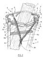
- the ladder comprises a safety device 5 which comprises two tubes of rectangular section 6 each engaged at the top of one of the uprights 2 a , 2 b of the ladder and tightened by collars 6 a , 6 b .
- Sleeves 7 are welded to the outer lateral face of the tubes 6 in a direction such that said sleeves 7 are substantially vertical when the ladder is pressed against the post 1, as seen in FIG. 1.
- Each sleeve 7 receives the vertical branch of an arm 8, able to pivot in said sleeve.
- a pin 9 axially retains each arm in the corresponding sleeve.
- Each arm 8 is thus able to pivot in a substantially horizontal plane, as will be explained with reference to FIGS. 3 to 6.
- Torsion springs are fixed on the one hand to the lower end of each arm, on the other hand to the corresponding tube and ensure the return of the arms to the closed position shown in FIG. 3.
- each arm 8 ends in a curved part, the curvature of which is directed towards the ladder so as to effectively clamp the post 1 by immobilizing it in an area situated substantially at equal distance from the two sleeves 7.
- the safety device 5 also includes a bearing surface 10 which is constituted by a curved bar 11 which is substantially V-shaped, the two branches of which support rollers 12 capable of rotating freely around the bar 11.
- the ends of the bar 11 are welded to the tubes 6.
- the ladder is applied against the post by its bearing surface 10, and more precisely by its rollers 12, which, by being able to roll along the post, facilitate the positioning of the ladder and possibly its deployment avoiding wear of the bearing surface 10 against the post, which is especially advantageous when the post is made of cement.
- Each strand 15 a , 15 b of the rope is guided in an eyelet 18 which is produced on a rod 19 parallel to the curved bar 11, welded at its ends to the two tubes 6 and in its middle to the curved bar 11.
- the safety device is shown with its arms 8 retracted, that is to say that the arms 8 are in the open position and are folded down on the side of the ladder opposite to the post 1.
- the ladder can be applied against the post 1 by its rollers 12, which facilitate the sliding of the upper part of the ladder against the post.
- each arm 8 pivots about 320 ° in the direction of its opening, that is to say, relative to Figure 2 , counterclockwise for the arm corresponding to the amount 2 a and clockwise for the arm corresponding to the amount 2 b .
- each strand 15 a , 15 b of the cord 13 is wound around the vertical branch of the corresponding arm 8.
- the strands 15 a and 15 b wound around the vertical branches of the arms 8 do not overlap, which makes it possible to avoid friction of the rope on itself, friction which could lead to wear of the rope and blockage of the arms 8.
- the arms 8 After having pivoted about half a turn, the arms 8 reach the position shown in FIG. 5.
- the strands 15 a and 15 b of the rope are then fully unwound and stretch between the connecting rod 16 and the corresponding eyelet 18.
- the rods can avoid causing the strands 15 a , 15 b to rub against the post, which is advantageous in particular when it is a post in concrete.
- the user stretches the rope 13 along the ladder and attaches it to the bottom of the ladder.
- the rope can therefore be a little loose, the arms then not being tightly tightened against the post but kept in a position in which they enclose the post against the bearing surface.
- a blocker 20 secured to one of the bars of the ladder, as seen in FIG. 8.
- the blocker 20 prevents the rope from going up but allows it to slide down.
- the ladder is thus applied against the pole with its arms surrounding said pole.
- the user puts on a harness or a belt (not shown) which he connects to a self-locking handle 21, shown in FIG. 7, which is engaged on the rope 13 so as to be able to climb freely along this rope and to hang on said rope when it is pulled down.
- FIG. 7 there is shown in broken lines a mechanism for blocking the self-locking handle on the cord 13.
- the user can climb freely along the ladder, using the rope as a lifeline.
- the rope 13 can then exert maximum torque on the arms 8 because the links 16 and the strands 15 a , 15 b extend substantially perpendicular to the horizontal branches of the arms 8.
Landscapes
- Engineering & Computer Science (AREA)
- Mechanical Engineering (AREA)
- Architecture (AREA)
- Structural Engineering (AREA)
- Ladders (AREA)
Applications Claiming Priority (2)
| Application Number | Priority Date | Filing Date | Title |
|---|---|---|---|
| FR9512854 | 1995-10-31 | ||
| FR9512854A FR2740507B1 (fr) | 1995-10-31 | 1995-10-31 | Dispositif de securite pour echelle et echelle equipee d'un tel dispositif |
Publications (1)
| Publication Number | Publication Date |
|---|---|
| EP0771931A1 true EP0771931A1 (de) | 1997-05-07 |
Family
ID=9484098
Family Applications (1)
| Application Number | Title | Priority Date | Filing Date |
|---|---|---|---|
| EP96402323A Withdrawn EP0771931A1 (de) | 1995-10-31 | 1996-10-31 | Sicherheitsvorrichtung für eine Leiter, und Leiter mit solcher Vorrichtung |
Country Status (2)
| Country | Link |
|---|---|
| EP (1) | EP0771931A1 (de) |
| FR (1) | FR2740507B1 (de) |
Cited By (10)
| Publication number | Priority date | Publication date | Assignee | Title |
|---|---|---|---|---|
| GB2359326A (en) * | 2000-02-15 | 2001-08-22 | Harold Frederick Adshead | Portable ladder fitted with damage prevention roller |
| GB2447359A (en) * | 2007-03-08 | 2008-09-10 | Rapid Rail Internat Ltd | Ladder support |
| US20150075905A1 (en) * | 2013-09-18 | 2015-03-19 | Wing Enterprises, Incorporated | Ladder securing apparatus, ladders incorporating same and related methods |
| WO2016024157A1 (en) * | 2014-08-13 | 2016-02-18 | Altiseg Equipamentos De Seguranca De Trabalho Ltda-Epp | Mobile lifeline ladder system |
| WO2018018116A1 (pt) * | 2016-07-28 | 2018-02-01 | Jacques Levy | Disposição introduzida em equipamento com gancho para ancoragem de escada em cabos |
| US10294721B1 (en) * | 2017-05-15 | 2019-05-21 | Hossein Jafarmadar | Ladder for narrow structures |
| US10760338B2 (en) | 2012-10-09 | 2020-09-01 | Wing Enterprises, Incorporated | Ladder securing apparatuses, ladders incorporating same and related methods |
| CN112482984A (zh) * | 2020-11-25 | 2021-03-12 | 广东电网有限责任公司 | 一种梯子 |
| CN113648630A (zh) * | 2021-09-10 | 2021-11-16 | 安徽马钢矿业资源集团姑山矿业有限公司 | 一种爬绳训练防坠落装置 |
| US20240352794A1 (en) * | 2023-04-20 | 2024-10-24 | Werner Co. | Ladder coupling assembly for fall protection system |
Families Citing this family (1)
| Publication number | Priority date | Publication date | Assignee | Title |
|---|---|---|---|---|
| US10010068B2 (en) * | 2015-11-23 | 2018-07-03 | Ronald Berkbuegler | Ladder stand and tree securement mechanism therefor |
Citations (10)
| Publication number | Priority date | Publication date | Assignee | Title |
|---|---|---|---|---|
| US1522292A (en) * | 1924-06-17 | 1925-01-06 | Enssle William | Attachment for ladders |
| US1658191A (en) * | 1926-01-04 | 1928-02-07 | Gilbert J Gravning | Ladder attachment |
| US2232414A (en) * | 1939-10-09 | 1941-02-18 | Ray C Swann | Ladder anchoring means |
| DE903147C (de) * | 1951-12-30 | 1954-02-01 | August Moeller | Sicherungsvorrichtung fuer Leitern |
| DE1256378B (de) * | 1954-09-09 | 1967-12-14 | Frhr Reinhard Koenig Fachsenfe | Haltevorrichtung fuer Leitern |
| US3908791A (en) * | 1973-11-02 | 1975-09-30 | Unarco Industries | Safety clamp |
| US4071926A (en) * | 1974-05-09 | 1978-02-07 | D. B. Enterprises, Inc. | Safety device for ladder climbers |
| US4090587A (en) * | 1976-10-18 | 1978-05-23 | Pyle Edwin G | Ladder lock |
| EP0232206A2 (de) * | 1986-02-05 | 1987-08-12 | Anaplastiki Ltd. | Sicherheitsvorrichtung zur Stützung von Leitern und Gerüsten gegen Masten, Bäume, Säulen oder Gebäudefassaden |
| US5388664A (en) * | 1993-11-23 | 1995-02-14 | Bator; Eugene A. | Portable tree stand |
-
1995
- 1995-10-31 FR FR9512854A patent/FR2740507B1/fr not_active Expired - Fee Related
-
1996
- 1996-10-31 EP EP96402323A patent/EP0771931A1/de not_active Withdrawn
Patent Citations (10)
| Publication number | Priority date | Publication date | Assignee | Title |
|---|---|---|---|---|
| US1522292A (en) * | 1924-06-17 | 1925-01-06 | Enssle William | Attachment for ladders |
| US1658191A (en) * | 1926-01-04 | 1928-02-07 | Gilbert J Gravning | Ladder attachment |
| US2232414A (en) * | 1939-10-09 | 1941-02-18 | Ray C Swann | Ladder anchoring means |
| DE903147C (de) * | 1951-12-30 | 1954-02-01 | August Moeller | Sicherungsvorrichtung fuer Leitern |
| DE1256378B (de) * | 1954-09-09 | 1967-12-14 | Frhr Reinhard Koenig Fachsenfe | Haltevorrichtung fuer Leitern |
| US3908791A (en) * | 1973-11-02 | 1975-09-30 | Unarco Industries | Safety clamp |
| US4071926A (en) * | 1974-05-09 | 1978-02-07 | D. B. Enterprises, Inc. | Safety device for ladder climbers |
| US4090587A (en) * | 1976-10-18 | 1978-05-23 | Pyle Edwin G | Ladder lock |
| EP0232206A2 (de) * | 1986-02-05 | 1987-08-12 | Anaplastiki Ltd. | Sicherheitsvorrichtung zur Stützung von Leitern und Gerüsten gegen Masten, Bäume, Säulen oder Gebäudefassaden |
| US5388664A (en) * | 1993-11-23 | 1995-02-14 | Bator; Eugene A. | Portable tree stand |
Cited By (15)
| Publication number | Priority date | Publication date | Assignee | Title |
|---|---|---|---|---|
| GB2359326A (en) * | 2000-02-15 | 2001-08-22 | Harold Frederick Adshead | Portable ladder fitted with damage prevention roller |
| US6419045B2 (en) | 2000-02-15 | 2002-07-16 | Harold Frederick Adshead | Ladders |
| GB2359326B (en) * | 2000-02-15 | 2003-10-22 | Harold Frederick Adshead | Improvements in or relating to ladders |
| GB2447359A (en) * | 2007-03-08 | 2008-09-10 | Rapid Rail Internat Ltd | Ladder support |
| US10760338B2 (en) | 2012-10-09 | 2020-09-01 | Wing Enterprises, Incorporated | Ladder securing apparatuses, ladders incorporating same and related methods |
| US9593531B2 (en) * | 2013-09-18 | 2017-03-14 | Wing Enterprises, Inc. | Ladder securing apparatus, ladders incorporating same and related methods |
| US20150075905A1 (en) * | 2013-09-18 | 2015-03-19 | Wing Enterprises, Incorporated | Ladder securing apparatus, ladders incorporating same and related methods |
| WO2016024157A1 (en) * | 2014-08-13 | 2016-02-18 | Altiseg Equipamentos De Seguranca De Trabalho Ltda-Epp | Mobile lifeline ladder system |
| CN107075908A (zh) * | 2014-08-13 | 2017-08-18 | 阿尔蒂塞格安全工作设备公司 | 移动式救生索梯具系统 |
| WO2018018116A1 (pt) * | 2016-07-28 | 2018-02-01 | Jacques Levy | Disposição introduzida em equipamento com gancho para ancoragem de escada em cabos |
| US10294721B1 (en) * | 2017-05-15 | 2019-05-21 | Hossein Jafarmadar | Ladder for narrow structures |
| CN112482984A (zh) * | 2020-11-25 | 2021-03-12 | 广东电网有限责任公司 | 一种梯子 |
| CN113648630A (zh) * | 2021-09-10 | 2021-11-16 | 安徽马钢矿业资源集团姑山矿业有限公司 | 一种爬绳训练防坠落装置 |
| CN113648630B (zh) * | 2021-09-10 | 2022-04-26 | 安徽马钢矿业资源集团姑山矿业有限公司 | 一种爬绳训练防坠落装置 |
| US20240352794A1 (en) * | 2023-04-20 | 2024-10-24 | Werner Co. | Ladder coupling assembly for fall protection system |
Also Published As
| Publication number | Publication date |
|---|---|
| FR2740507B1 (fr) | 1997-12-05 |
| FR2740507A1 (fr) | 1997-04-30 |
Similar Documents
| Publication | Publication Date | Title |
|---|---|---|
| EP2399651B1 (de) | Abrutschblockiergerät für das Hoch- und Runterklettern an einem Seil | |
| CA2180440C (fr) | Appareil de securite anti-chute | |
| EP0608164B1 (de) | Bewegliche Verankerung die eine sichere waagerechte Verschiebung ermöglicht | |
| FR2720283A1 (fr) | Appareil anti-chute verrouillage automatiquement sur une corde de sécurité. | |
| EP0771931A1 (de) | Sicherheitsvorrichtung für eine Leiter, und Leiter mit solcher Vorrichtung | |
| FR2681790A1 (fr) | Methode et dispositif de remontee le long d'une corde. | |
| FR2600540A2 (fr) | Dispositif de securite pour circulation a grande hauteur. | |
| EP3713868B1 (de) | Tragbare hebevorrichtung | |
| FR2549923A1 (fr) | Serre-cable de frettage | |
| CH664891A5 (fr) | Sangle de levage et appareil de levage pour invalide muni de ladite sangle. | |
| FR3019202A1 (fr) | Potelet de garde-corps de securite a moyen d'anti-soulevement et garde-corps de securite comprenant une pluralite de tels potelets | |
| EP1230954A1 (de) | Demontierbares Trampolin | |
| EP4056327A1 (de) | Seil mit verstellbarer länge, anseilgurt, seilaufstiegsvorrichtung und anwendungsverfahren | |
| EP4066906A1 (de) | Vorrichtung zur befestigung an einen verankerungspunkt und verfahren zur anwendung einer solchen befestigungsvorrichtung | |
| FR2903570A1 (fr) | Dispositif d'accrochage de fils dits releveurs | |
| FR2511990A1 (fr) | Dispositif a chargement par le haut pour le deroulement en continu d'un fil metallique | |
| FR2587553A1 (fr) | Dispositif de suspension pour le deroulage, la mise en tension et le soutien d'un cable electrique torsade lourd equipe d'un cable porteur | |
| FR2711860A1 (fr) | Dispositif de crochet pour l'amarrage réglable des pinces d'ancrage associées aux câbles électriques aériens. | |
| FR2623241A1 (fr) | Dispositif d'ancrage d'une echelle sur un angle de poteau | |
| JP3751005B2 (ja) | 植樹安定装置 | |
| FR2654715A1 (en) | Pay-out for wires used for tying, especially in viticulture or arboriculture | |
| FR2599586A1 (fr) | Dispositif de capture d'animaux domestiques | |
| FR2691300A1 (fr) | Dispositif élévateur d'une armature de support de lignes électriques sur un poteau en bois. | |
| FR2532637A2 (fr) | Dispositif pour verrouiller des sangles au moment du levage de charges, eventuellement apres reglage de leur longueur utile | |
| FR2824447A1 (fr) | Echelle support pour la coupe d'arbres |
Legal Events
| Date | Code | Title | Description |
|---|---|---|---|
| PUAI | Public reference made under article 153(3) epc to a published international application that has entered the european phase |
Free format text: ORIGINAL CODE: 0009012 |
|
| AK | Designated contracting states |
Kind code of ref document: A1 Designated state(s): AT BE CH DE ES GB IT LI |
|
| 17P | Request for examination filed |
Effective date: 19970530 |
|
| 17Q | First examination report despatched |
Effective date: 19990416 |
|
| GRAG | Despatch of communication of intention to grant |
Free format text: ORIGINAL CODE: EPIDOS AGRA |
|
| GRAG | Despatch of communication of intention to grant |
Free format text: ORIGINAL CODE: EPIDOS AGRA |
|
| GRAH | Despatch of communication of intention to grant a patent |
Free format text: ORIGINAL CODE: EPIDOS IGRA |
|
| STAA | Information on the status of an ep patent application or granted ep patent |
Free format text: STATUS: THE APPLICATION IS DEEMED TO BE WITHDRAWN |
|
| 18D | Application deemed to be withdrawn |
Effective date: 20030313 |