EP0771945B1 - Schubumkehrvorrichtung mit Sekundärklappen für ein Bläsertriebwerk - Google Patents
Schubumkehrvorrichtung mit Sekundärklappen für ein Bläsertriebwerk Download PDFInfo
- Publication number
- EP0771945B1 EP0771945B1 EP96402300A EP96402300A EP0771945B1 EP 0771945 B1 EP0771945 B1 EP 0771945B1 EP 96402300 A EP96402300 A EP 96402300A EP 96402300 A EP96402300 A EP 96402300A EP 0771945 B1 EP0771945 B1 EP 0771945B1
- Authority
- EP
- European Patent Office
- Prior art keywords
- flap
- wall
- thrust reverser
- closed position
- secondary flap
- Prior art date
- Legal status (The legal status is an assumption and is not a legal conclusion. Google has not performed a legal analysis and makes no representation as to the accuracy of the status listed.)
- Expired - Lifetime
Links
- 238000011144 upstream manufacturing Methods 0.000 claims description 30
- 230000002441 reversible effect Effects 0.000 claims description 15
- 238000007688 edging Methods 0.000 claims 1
- 230000000694 effects Effects 0.000 description 8
- 210000003462 vein Anatomy 0.000 description 7
- 230000008901 benefit Effects 0.000 description 6
- 210000004027 cell Anatomy 0.000 description 4
- 230000015572 biosynthetic process Effects 0.000 description 2
- 238000000034 method Methods 0.000 description 2
- RZVHIXYEVGDQDX-UHFFFAOYSA-N 9,10-anthraquinone Chemical compound C1=CC=C2C(=O)C3=CC=CC=C3C(=O)C2=C1 RZVHIXYEVGDQDX-UHFFFAOYSA-N 0.000 description 1
- 230000000903 blocking effect Effects 0.000 description 1
- 238000007664 blowing Methods 0.000 description 1
- 230000032798 delamination Effects 0.000 description 1
- 230000001627 detrimental effect Effects 0.000 description 1
- 238000006073 displacement reaction Methods 0.000 description 1
- 230000004907 flux Effects 0.000 description 1
- 230000004048 modification Effects 0.000 description 1
- 238000012986 modification Methods 0.000 description 1
- 238000005457 optimization Methods 0.000 description 1
- 230000002028 premature Effects 0.000 description 1
- 239000003380 propellant Substances 0.000 description 1
- 238000005086 pumping Methods 0.000 description 1
- 230000009467 reduction Effects 0.000 description 1
- 230000000717 retained effect Effects 0.000 description 1
- 238000004513 sizing Methods 0.000 description 1
- 230000000087 stabilizing effect Effects 0.000 description 1
- XLYOFNOQVPJJNP-UHFFFAOYSA-N water Substances O XLYOFNOQVPJJNP-UHFFFAOYSA-N 0.000 description 1
Images


Classifications
-
- F—MECHANICAL ENGINEERING; LIGHTING; HEATING; WEAPONS; BLASTING
- F02—COMBUSTION ENGINES; HOT-GAS OR COMBUSTION-PRODUCT ENGINE PLANTS
- F02K—JET-PROPULSION PLANTS
- F02K1/00—Plants characterised by the form or arrangement of the jet pipe or nozzle; Jet pipes or nozzles peculiar thereto
- F02K1/54—Nozzles having means for reversing jet thrust
- F02K1/64—Reversing fan flow
- F02K1/70—Reversing fan flow using thrust reverser flaps or doors mounted on the fan housing
-
- F—MECHANICAL ENGINEERING; LIGHTING; HEATING; WEAPONS; BLASTING
- F05—INDEXING SCHEMES RELATING TO ENGINES OR PUMPS IN VARIOUS SUBCLASSES OF CLASSES F01-F04
- F05D—INDEXING SCHEME FOR ASPECTS RELATING TO NON-POSITIVE-DISPLACEMENT MACHINES OR ENGINES, GAS-TURBINES OR JET-PROPULSION PLANTS
- F05D2270/00—Control
- F05D2270/01—Purpose of the control system
- F05D2270/17—Purpose of the control system to control boundary layer
- F05D2270/173—Purpose of the control system to control boundary layer by the Coanda effect
-
- Y—GENERAL TAGGING OF NEW TECHNOLOGICAL DEVELOPMENTS; GENERAL TAGGING OF CROSS-SECTIONAL TECHNOLOGIES SPANNING OVER SEVERAL SECTIONS OF THE IPC; TECHNICAL SUBJECTS COVERED BY FORMER USPC CROSS-REFERENCE ART COLLECTIONS [XRACs] AND DIGESTS
- Y02—TECHNOLOGIES OR APPLICATIONS FOR MITIGATION OR ADAPTATION AGAINST CLIMATE CHANGE
- Y02T—CLIMATE CHANGE MITIGATION TECHNOLOGIES RELATED TO TRANSPORTATION
- Y02T50/00—Aeronautics or air transport
- Y02T50/60—Efficient propulsion technologies, e.g. for aircraft
Definitions
- a wall can also cover the outside of the engine, this is to say the outside of the casing that surrounds the blower and the exterior of the exterior wall of the conduit described above, this to minimize the drag of the whole propellant.
- This is particularly the case of propulsion systems reported on the exterior of aircraft, particularly when these propulsion systems are attached under the wings or at the rear of the fuselage.
- We will call rollover exterior the assembly formed by the exterior wall of the duct and through the outer wall of the nacelle.
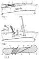
- Figure 1 of the accompanying drawings shows a known example of realization of a thrust reverser of this type composed of three main parts, a fixed part 1, located in upstream, in the extension of the external wall of the secondary flow which is internally delimited by the central structure envelope of the turbojet engine, movable part 2 and a fixed rear ferrule 3.
- Said part fixed upstream 1 comprises an external nacelle panel 4, a internal panel 5 externally limiting the flow stream secondary and a front frame 6 which ensures the junction of said panels 4 and 5.
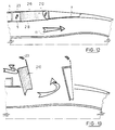
- an optimal clipping 21 of the secondary door 10 along the upstream fixed panel and the outer door panel main 7 allows control of the water tables and including preventing re-ingestion or jet impact likely to deteriorate control of the aircraft in phase landing.
- grooves and / or baffles 22 can be added on the upper surface 16 and / or the lower surface 18 secondary door 10 to direct so three-dimensional the jet in the desired direction and ensure better flow guidance.
- creating of a neck is advantageous when the flow is slow and at high flow.
Landscapes
- Engineering & Computer Science (AREA)
- Chemical & Material Sciences (AREA)
- Combustion & Propulsion (AREA)
- Mechanical Engineering (AREA)
- General Engineering & Computer Science (AREA)
- Structures Of Non-Positive Displacement Pumps (AREA)
Claims (12)
- Schubumkehrvorrichtung für ein Zweikreis-TL-Triebwerk, die Hauptklappen (7) aufweist, die sich im Direktschubbetrieb in geschlossener Stellung in die Außenverkleidung einfügen können und in ausgeklappter Stellung unter Einwirkung eines Steuermittels für die Bewegungen wie z. B. eines Zylinders (7a) dergestalt um seitliche, an dem festen Aufbau der Umkehrvorrichtung sitzende Drehzapfen schwenken können, daß sie zumindest einen Teil des Ausstoßstroms (11a) des Turbotriebwerks durch einen Raum umlenken, der einen Umkehrschacht bildet, und dabei eine Schubumkehr gewährleisten, und mindestens ein zusätzliches bewegliches Element aufweist, das Sekundärklappe (10; 110; 210; 310) genannt wird und direkt mit dem Aufbau der Umkehrvorrichtung verbunden ist und sich im Direktschubbetrieb in die Außenverkleidung einfügen kann und sich im Schubumkehrbetrieb am vorderen Rand des Umkehrschachts (24b) ausklappen kann,
dadurch gekennzeichnet, daß die Vorderseite der Sekundärklappe (10; 110; 210; 310) in der gleichen Richtung wie die der Hauptklappe (7) in einer Zentrifugalrichtung schwenkt, so daß für den äußeren Strom (14), der über die Oberfläche der Außenwand (4) der Gondel strömt, ein Hindernis entsteht, und daß der Umkehrstrom kanalisiert wird, indem mit der Klappe eine Umkehrstromleitung gebildet wird, die aus der Außenverkleidung hervorsteht. - Schubumkehrvorrichtung für ein Zweikreis-TL-Triebwerk nach Anspruch 1, bei der die genannte Sekundärklappe (10) in geschlossener Stellung zwischen einem hinteren Teil (12) der Außenverkleidung und einer Außenplatte (13) der zugehörigen Hauptklappe (7) angeordnet ist.
- Schubumkehrvorrichtung für ein Zweikreis-TL-Triebwerk nach Anspruch 2, bei der das in geschlossener Stellung hintere Ende (15) dieser Sekundärklappe (10) ein Profil dergestalt aufweist, daß es in ausgeklappter Stellung, die dem Schubumkehrbetrieb entspricht, einen bestimmten Umlenkrand bildet, der den vorderen Rand des Umkehrschachts bildet, wobei das in geschlossener Stellung vordere Ende (20) dieser Sekundärklappe (10) ein Profil dergestalt aufweist, daß es einen bestimmten Umlenkrand bildet, der die Ströme so effektiv wie möglich ausrichtet, und die Druckseite (18) und die Saugseite (16) ein bestimmtes Profil aufweisen, das geeignet ist, die aerodynamischen Strömungen und gewünschten Leistungen im Umkehrschub wirksam zu erreichen.
- Schubumkehrvorrichtung für ein Zweikreis-TL-Triebwerk nach Anspruch 3, bei der diese Sekundärklappe (10) eine Stufe (17) aufweist, die an der Saugseite (16) ausgeführt ist, um einen örtlich begrenzten Unterdruck zu schaffen, ferner zwischen der Saugseite (16) und der Druckseite (18) Löcher oder Schlitze (19) aufweist und auf dieser Saugseite (16) und der Druckseite (18) Stauränder oder Rillen (22) mit bestimmten Abmessungen und Ausrichtungen aufweist, um die Richtung und Führung der aerodynamischen Strömungen zu gewährleisten.
- Schubumkehrvorrichtung für ein Zweikreis-TL-Triebwerk nach einem der Ansprüche 3 oder 4, bei der diese Sekundärklappe (10) ein bestimmtes Außenprofil (21) aufweist, um das Steuern der Strombahnen des Umkehrstroms (11a) zu gewährleisten.
- Schubumkehrvorrichtung für ein Zweikreis-TL-Triebwerk nach einem der Ansprüche 2 bis 5, bei der diese Sekundärklappe (10) in ausgeklappter Stellung in den inneren Strom mündet, wobei das in geschlossener Stellung hintere Ende (15) der Sekundärklappe radial gegenüber der feststehenden Wand (12) innen angeordnet ist.
- Schubumkehrvorrichtung für ein Zweikreis-TL-Triebwerk nach Anspruch 1, bei der die genannte Sekundärklappe (110) in geschlossener Stellung von einer Außenplatte (13) der Hauptklappe (7) überdeckt wird und eine Druckseite (118) bildet, die im Direktstrahlbetrieb unter Kontinuität zwischen der vorderen festen Wand (5) und der Innenwand der Hauptklappe (7) einen Teil der Außenwand der Turbotriebwerksleitung bildet.
- Schubumkehrvorrichtung für ein Zweikreis-TL-Triebwerk nach Anspruch 1, bei der die genannte Sekundärklappe (210) eine Druckseite (218) aufweist, die in geschlossener Stellung die Kontinuität zwischen der Innenwand (5) des vorderen festen Aufbaus und der Innenwand der jeweiligen Hauptklappe (7) gewährleistet, sowie eine Saugseite (216) aufweist, die gleichzeitig in geschlossener Stellung ebenfalls Kontinuität zwischen der Außenwand (4) des vorderen festen Aufbaus und der Außenwand der Hauptklappe (7) gewährleistet, so daß diese Sekundärklappe (210) im Direktstrahlbetrieb zugleich die Führung der aerodynamischen Strömungen des Turbotriebwerkstroms (11) und des Außenstroms der Gondel teilweise gewährleistet.
- Schubumkehrvorrichtung für ein Zweikreis-TL-Triebwerk nach Anspruch 1, bei der die genannte Sekundärklappe (310) eine Saugseite (316) aufweist, die in geschlossener Stellung die Kontinuität zwischen der Außenwand (4) des vorderen festen Aufbaus und der Außenwand der zugehörigen Hauptklappe (7) gewährleistet, und wobei diese Sekundärklappe (310) sich in geschlossener Stellung über einem inneren hinteren Teil (12) des vorderen festen Aufbaus befindet, der sich im Direktstrahlbetrieb in Kontinuität an die Innenwand der Hauptklappe (7) anschließt.
- Schubumkehrvorrichtung für ein Zweikreis-TL-Triebwerk nach einem der Ansprüche 8 oder 9, bei der vorne an dieser Sekundärklappe (210; 310) zusätzlich ein beweglicher Spoiler (23; 33) dergestalt angeordnet wird, daß er ihre Wirksamkeit in Umkehrschubbetrieb erhöht.
- Schubumkehrvorrichtung für ein Zweikreis-TL-Triebwerk nach einem der Ansprüche 9 oder 10, bei der in bestimmten Flugphasen des Flugzeugs im Direktstrahlbetrieb des Turbotriebwerks diese Sekundärklappe (310) ausgeklappt werden kann und die Hauptklappe (7) dabei in geschlossener Stellung gehalten wird.
- Schubumkehrvorrichtung für ein Zweikreis-TL-Triebwerk nach einem der Ansprüche 1 bis 11, bei der diese Sekundärklappe (10; 110; 210; 310) sich je nach dem vom Turbotriebwerk kommenden Gegenschubstrom unabhängig von oder gemeinsam mit der Hauptklappe (7) ausklappt und dabei eine maximale Wirksamkeit der Luftumlenkfunktion dieser Sekundärklappe bei den Gegenschubphasen aufrecht erhält.
Applications Claiming Priority (2)
| Application Number | Priority Date | Filing Date | Title |
|---|---|---|---|
| FR9512887A FR2740834B1 (fr) | 1995-11-02 | 1995-11-02 | Inverseur de poussee de turboreacteur a double flux muni de portes secondaires |
| FR9512887 | 1995-11-02 |
Publications (2)
| Publication Number | Publication Date |
|---|---|
| EP0771945A1 EP0771945A1 (de) | 1997-05-07 |
| EP0771945B1 true EP0771945B1 (de) | 2001-01-10 |
Family
ID=9484121
Family Applications (1)
| Application Number | Title | Priority Date | Filing Date |
|---|---|---|---|
| EP96402300A Expired - Lifetime EP0771945B1 (de) | 1995-11-02 | 1996-10-30 | Schubumkehrvorrichtung mit Sekundärklappen für ein Bläsertriebwerk |
Country Status (6)
| Country | Link |
|---|---|
| US (1) | US5819528A (de) |
| EP (1) | EP0771945B1 (de) |
| JP (1) | JPH09166046A (de) |
| CA (1) | CA2189217A1 (de) |
| DE (1) | DE69611506T2 (de) |
| FR (1) | FR2740834B1 (de) |
Cited By (2)
| Publication number | Priority date | Publication date | Assignee | Title |
|---|---|---|---|---|
| US9573695B2 (en) | 2013-02-22 | 2017-02-21 | United Technologies Corporation | Integrated nozzle and plug |
| US9581108B2 (en) | 2013-02-22 | 2017-02-28 | United Technologies Corporation | Pivot thrust reverser with multi-point actuation |
Families Citing this family (30)
| Publication number | Priority date | Publication date | Assignee | Title |
|---|---|---|---|---|
| GB9613166D0 (en) * | 1996-06-24 | 1996-08-28 | Short Brothers Plc | Aircraft propulsive power unit |
| FR2751377B1 (fr) * | 1996-07-18 | 1998-09-04 | Hispano Suiza Sa | Inverseur de poussee de turboreacteur a portes comportant un panneau coulissant |
| FR2764341B1 (fr) * | 1997-06-05 | 1999-07-16 | Hispano Suiza Sa | Inverseur de poussee de turboreacteur a portes formant ecopes associees a un deflecteur mobile |
| FR2764340B1 (fr) * | 1997-06-05 | 1999-07-16 | Hispano Suiza Sa | Inverseur de poussee de turboreacteur a portes munies d'un becquet mobile a entrainement optimise |
| FR2764339B1 (fr) * | 1997-06-05 | 1999-07-16 | Hispano Suiza Sa | Inverseur de poussee de turboreacteur a portes formant ecopes associees a une casquette amont mobile |
| EP0926333A1 (de) * | 1997-12-26 | 1999-06-30 | SOCIETE DE CONSTRUCTION DES AVIONS HUREL-DUBOIS (société anonyme) | Konfiguration einer Schubumkehrvorrichtung |
| US6293495B1 (en) * | 1999-12-08 | 2001-09-25 | Rohr, Inc. | Pivoting door thrust reverser system for turbofan aircraft jet engine |
| US6311928B1 (en) | 2000-01-05 | 2001-11-06 | Stage Iii Technologies, L.C. | Jet engine cascade thrust reverser for use with mixer/ejector noise suppressor |
| US20040149861A1 (en) * | 2001-06-06 | 2004-08-05 | Strobl William Charles | S & H Cycle Engine |
| US6845946B2 (en) * | 2003-02-21 | 2005-01-25 | The Nordam Group, Inc. | Self stowing thrust reverser |
| US20110101158A1 (en) * | 2005-03-29 | 2011-05-05 | The Boeing Company | Thrust Reversers Including Monolithic Components |
| US7571527B2 (en) * | 2005-03-29 | 2009-08-11 | The Boeing Company | Mandrel for fabrication of a monolithic composite nacelle panel |
| US7690190B2 (en) | 2005-05-11 | 2010-04-06 | The Boeing Company | Aircraft systems including cascade thrust reversers |
| US7559507B2 (en) * | 2005-06-27 | 2009-07-14 | The Boeing Company | Thrust reversers including locking assemblies for inhibiting deflection |
| US7600371B2 (en) | 2005-10-18 | 2009-10-13 | The Boeing Company | Thrust reversers including support members for inhibiting deflection |
| US8015797B2 (en) | 2006-09-21 | 2011-09-13 | Jean-Pierre Lair | Thrust reverser nozzle for a turbofan gas turbine engine |
| WO2008045050A1 (en) * | 2006-10-12 | 2008-04-17 | United Technologies Corporation | Gas turbine engine with fan variable area nozzle, nacelle assembly and method of varying area of a fan nozzle |
| US8172175B2 (en) | 2007-11-16 | 2012-05-08 | The Nordam Group, Inc. | Pivoting door thrust reverser for a turbofan gas turbine engine |
| US8052086B2 (en) | 2007-11-16 | 2011-11-08 | The Nordam Group, Inc. | Thrust reverser door |
| US8052085B2 (en) | 2007-11-16 | 2011-11-08 | The Nordam Group, Inc. | Thrust reverser for a turbofan gas turbine engine |
| US8091827B2 (en) | 2007-11-16 | 2012-01-10 | The Nordam Group, Inc. | Thrust reverser door |
| US7735778B2 (en) | 2007-11-16 | 2010-06-15 | Pratt & Whitney Canada Corp. | Pivoting fairings for a thrust reverser |
| US8051639B2 (en) | 2007-11-16 | 2011-11-08 | The Nordam Group, Inc. | Thrust reverser |
| FR2968635B1 (fr) * | 2010-12-14 | 2012-12-14 | Aircelle Sa | Nacelle pour turboreacteur d’aeronef double flux |
| FR2985782B1 (fr) * | 2012-01-17 | 2015-07-24 | Aircelle Sa | Inverseur de poussee a portes jumelles |
| US10309343B2 (en) * | 2014-11-06 | 2019-06-04 | Rohr, Inc. | Split sleeve hidden door thrust reverser |
| US10451002B2 (en) * | 2016-01-22 | 2019-10-22 | Honeywell International Inc. | Translating cowl thrust reverser that prevents unintended door rotation |
| US10267262B2 (en) | 2016-05-06 | 2019-04-23 | Mra Systems, Llc | Thrust reverser assembly |
| US10641207B2 (en) * | 2017-07-21 | 2020-05-05 | The Boeing Company | Air flow deflector assembly for a thrust reverser system for reducing re-ingestion of reverse efflux air flow and method for the same |
| CN112455699B (zh) * | 2020-11-13 | 2024-01-02 | 中国航空工业集团公司沈阳飞机设计研究所 | 一种高融合飞机后体 |
Family Cites Families (20)
| Publication number | Priority date | Publication date | Assignee | Title |
|---|---|---|---|---|
| FR1482538A (fr) | 1965-06-07 | 1967-05-26 | Gen Electric | Inverseur de poussée |
| US3279182A (en) * | 1965-06-07 | 1966-10-18 | Gen Electric | Thrust reverser |
| GB1177864A (en) * | 1968-04-09 | 1970-01-14 | Rolls Royce | Thrust Reverser or Spoiler |
| GB1181746A (en) | 1968-06-19 | 1970-02-18 | Rolls Royce | Thrust Reverser for Jet Propulsion Plant |
| US3614037A (en) * | 1969-09-22 | 1971-10-19 | Boeing Co | Aircraft combination thrust reverser and sound suppressor and a particular full range balanced thrust reverser |
| US3601992A (en) * | 1970-06-10 | 1971-08-31 | Rohr Corp | Thrust reversing apparatus |
| US3605411A (en) * | 1970-07-01 | 1971-09-20 | Rohr Corp | Thrust reversing apparatus |
| FR2146109A1 (de) * | 1971-07-19 | 1973-03-02 | Bruner Georges | |
| US3739582A (en) * | 1972-04-13 | 1973-06-19 | Rohr Industries Inc | Thrust reversing apparatus |
| GB1605235A (en) * | 1976-05-05 | 1985-06-12 | British Aerospace | Aircraft thrust reversing devices |
| FR2618852B1 (fr) * | 1987-07-29 | 1989-11-10 | Hispano Suiza Sa | Inverseur de poussee de turboreacteur muni d'un dispositif redresseur de flux |
| FR2618853B1 (fr) | 1987-07-29 | 1989-11-10 | Hispano Suiza Sa | Inverseur de poussee de turboreacteur muni d'un deflecteur mobile de porte |
| FR2621082A1 (fr) | 1987-09-30 | 1989-03-31 | Hispano Suiza Sa | Inverseur de poussee de turboreacteur a portes munies d'une plaque au profil de veine |
| FR2627807B1 (fr) * | 1988-02-25 | 1990-06-29 | Hispano Suiza Sa | Inverseur de poussee de turboreacteur a double flux equipe de bords de deviation munis de levres mobiles |
| FR2634251B1 (fr) | 1988-07-18 | 1993-08-13 | Hispano Suiza Sa | Inverseur de poussee de turboreacteur a double flux equipe de bords de deviation mobiles |
| FR2638207B1 (fr) * | 1988-10-20 | 1990-11-30 | Hispano Suiza Sa | Inverseur de poussee de turboreacteur, a portes pivotantes equilibrees |
| US5039171A (en) * | 1989-08-18 | 1991-08-13 | Societe Anonyme Dite Hispano-Suiza | Multi-panel thrust reverser door |
| FR2651021B1 (fr) * | 1989-08-18 | 1994-05-06 | Hispano Suiza Sa | Inverseur de poussee de turboreacteur, a portes associees a un panneau amont |
| JPH06241203A (ja) * | 1993-02-12 | 1994-08-30 | Komatsu Ltd | 走行用油圧回路 |
| JP3253033B2 (ja) * | 1993-02-12 | 2002-02-04 | 株式会社小松製作所 | 走行用油圧回路 |
-
1995
- 1995-11-02 FR FR9512887A patent/FR2740834B1/fr not_active Expired - Fee Related
-
1996
- 1996-10-30 DE DE69611506T patent/DE69611506T2/de not_active Expired - Fee Related
- 1996-10-30 EP EP96402300A patent/EP0771945B1/de not_active Expired - Lifetime
- 1996-10-30 US US08/740,556 patent/US5819528A/en not_active Expired - Fee Related
- 1996-10-30 CA CA002189217A patent/CA2189217A1/fr not_active Abandoned
- 1996-11-01 JP JP8292137A patent/JPH09166046A/ja active Pending
Cited By (10)
| Publication number | Priority date | Publication date | Assignee | Title |
|---|---|---|---|---|
| US9573695B2 (en) | 2013-02-22 | 2017-02-21 | United Technologies Corporation | Integrated nozzle and plug |
| US9581108B2 (en) | 2013-02-22 | 2017-02-28 | United Technologies Corporation | Pivot thrust reverser with multi-point actuation |
| US9611048B2 (en) | 2013-02-22 | 2017-04-04 | United Technologies Corporation | ATR axial V-groove |
| US9617009B2 (en) | 2013-02-22 | 2017-04-11 | United Technologies Corporation | ATR full ring sliding nacelle |
| US9631578B2 (en) | 2013-02-22 | 2017-04-25 | United Technologies Corporation | Pivot thrust reverser surrounding inner surface of bypass duct |
| US9670876B2 (en) | 2013-02-22 | 2017-06-06 | United Technologies Corporation | Tandem thrust reverser with sliding rails |
| US9694912B2 (en) | 2013-02-22 | 2017-07-04 | United Technologies Corporation | ATR guide pins for sliding nacelle |
| US9695778B2 (en) | 2013-02-22 | 2017-07-04 | United Technologies Corporation | Tandem thrust reverser with multi-point actuation |
| US9822734B2 (en) | 2013-02-22 | 2017-11-21 | United Technologies Corporation | Tandem thrust reverser with multi-bar linkage |
| US9970388B2 (en) | 2013-02-22 | 2018-05-15 | United Technologies Corporation | Tandem thrust reverser with sliding rails |
Also Published As
| Publication number | Publication date |
|---|---|
| US5819528A (en) | 1998-10-13 |
| EP0771945A1 (de) | 1997-05-07 |
| DE69611506D1 (de) | 2001-02-15 |
| FR2740834A1 (fr) | 1997-05-09 |
| FR2740834B1 (fr) | 1997-12-05 |
| JPH09166046A (ja) | 1997-06-24 |
| CA2189217A1 (fr) | 1997-05-03 |
| DE69611506T2 (de) | 2001-06-07 |
Similar Documents
| Publication | Publication Date | Title |
|---|---|---|
| EP0771945B1 (de) | Schubumkehrvorrichtung mit Sekundärklappen für ein Bläsertriebwerk | |
| CA2213049C (fr) | Inverseur de poussee de turboreacteur a portes formant ecopes | |
| EP0853192B1 (de) | Schubumkehrvorrichtung mit optimierter Anordnung des Gitterbetätigungsorgans | |
| EP0534815B1 (de) | Schubumkehrvorrichtung mit verbesserter Umlenkung der Gasstrahlen | |
| EP0851111B1 (de) | Schubumkehrvorrichtung für ein Strahltriebwerk mit Klappe am Hinterteil | |
| EP0806563B1 (de) | Klappen mit Leitflächen für eine Schubumkehrvorrichtung eines Bläsertriebwerkes | |
| CA2240095A1 (fr) | Inverseur de poussee a portes de turboreacteur a section variable d'ejection | |
| EP0530078A1 (de) | Schubumkehrvorrichtung mit einer gekrümmten Umlenkkante für einen Strahlmotor | |
| EP0754849B1 (de) | Schubumkehrvorrichtung für ein Zweikreistriebwerk mit unsymmetrischen Klappen | |
| WO1999046498A1 (fr) | Inverseur de poussee de turboreacteur a portes formant ecopes associees a une grille mobile | |
| EP0761957A1 (de) | Schubumkehrvorrichtung für ein Strahltriebwerk von mit dem Vorderteil verbundenen Klappen | |
| FR2764339A1 (fr) | Inverseur de poussee de turboreacteur a portes formant ecopes associees a une casquette amont mobile | |
| WO1999015771A1 (fr) | Inverseur de poussee de turboreacteur a coquilles internes | |
| CA2240094A1 (fr) | Turboreacteur a double flux associe a un inverseur de poussee avec un carenage rapporte dans la veine fluide | |
| EP0965744A1 (de) | Schubumkehrvorrichtung für ein Bläsertriebwerk mit Umkehrklappen, die Kanäle mit veränderlichem Ausflussquerschnitt formen | |
| WO1997043537A1 (fr) | Inverseur de poussee de turboreacteur a portes associees a un panneau amont | |
| FR2751377A1 (fr) | Inverseur de poussee de turboreacteur a portes comportant un panneau coulissant | |
| EP0728933B1 (de) | Schubumkehrvorrichtung mit dem Hinterteil verbundenen Klappen | |
| US20090126342A1 (en) | Thrust Reverser Door | |
| FR2757570A1 (fr) | Inverseur de poussee de turboreacteur a guidage du flux d'inversion ameliore | |
| FR2750737A1 (fr) | Inverseur de poussee de turboreacteur a portes a pilotage de nappes ameliore |
Legal Events
| Date | Code | Title | Description |
|---|---|---|---|
| PUAI | Public reference made under article 153(3) epc to a published international application that has entered the european phase |
Free format text: ORIGINAL CODE: 0009012 |
|
| 17P | Request for examination filed |
Effective date: 19961118 |
|
| AK | Designated contracting states |
Kind code of ref document: A1 Designated state(s): DE FR GB IT |
|
| 17Q | First examination report despatched |
Effective date: 19990617 |
|
| GRAG | Despatch of communication of intention to grant |
Free format text: ORIGINAL CODE: EPIDOS AGRA |
|
| RAP1 | Party data changed (applicant data changed or rights of an application transferred) |
Owner name: HISPANO-SUIZA AEROSTRUCTURES |
|
| GRAG | Despatch of communication of intention to grant |
Free format text: ORIGINAL CODE: EPIDOS AGRA |
|
| GRAH | Despatch of communication of intention to grant a patent |
Free format text: ORIGINAL CODE: EPIDOS IGRA |
|
| GRAH | Despatch of communication of intention to grant a patent |
Free format text: ORIGINAL CODE: EPIDOS IGRA |
|
| GRAA | (expected) grant |
Free format text: ORIGINAL CODE: 0009210 |
|
| AK | Designated contracting states |
Kind code of ref document: B1 Designated state(s): DE FR GB IT |
|
| ITF | It: translation for a ep patent filed | ||
| REF | Corresponds to: |
Ref document number: 69611506 Country of ref document: DE Date of ref document: 20010215 |
|
| GBT | Gb: translation of ep patent filed (gb section 77(6)(a)/1977) |
Effective date: 20010205 |
|
| PLBE | No opposition filed within time limit |
Free format text: ORIGINAL CODE: 0009261 |
|
| STAA | Information on the status of an ep patent application or granted ep patent |
Free format text: STATUS: NO OPPOSITION FILED WITHIN TIME LIMIT |
|
| REG | Reference to a national code |
Ref country code: GB Ref legal event code: IF02 |
|
| 26N | No opposition filed | ||
| PGFP | Annual fee paid to national office [announced via postgrant information from national office to epo] |
Ref country code: FR Payment date: 20030922 Year of fee payment: 8 |
|
| PGFP | Annual fee paid to national office [announced via postgrant information from national office to epo] |
Ref country code: GB Payment date: 20031029 Year of fee payment: 8 |
|
| PGFP | Annual fee paid to national office [announced via postgrant information from national office to epo] |
Ref country code: DE Payment date: 20031219 Year of fee payment: 8 |
|
| PG25 | Lapsed in a contracting state [announced via postgrant information from national office to epo] |
Ref country code: GB Free format text: LAPSE BECAUSE OF NON-PAYMENT OF DUE FEES Effective date: 20041030 |
|
| PG25 | Lapsed in a contracting state [announced via postgrant information from national office to epo] |
Ref country code: DE Free format text: LAPSE BECAUSE OF NON-PAYMENT OF DUE FEES Effective date: 20050503 |
|
| GBPC | Gb: european patent ceased through non-payment of renewal fee |
Effective date: 20041030 |
|
| PG25 | Lapsed in a contracting state [announced via postgrant information from national office to epo] |
Ref country code: FR Free format text: LAPSE BECAUSE OF NON-PAYMENT OF DUE FEES Effective date: 20050630 |
|
| REG | Reference to a national code |
Ref country code: FR Ref legal event code: ST |
|
| PG25 | Lapsed in a contracting state [announced via postgrant information from national office to epo] |
Ref country code: IT Free format text: LAPSE BECAUSE OF NON-PAYMENT OF DUE FEES;WARNING: LAPSES OF ITALIAN PATENTS WITH EFFECTIVE DATE BEFORE 2007 MAY HAVE OCCURRED AT ANY TIME BEFORE 2007. THE CORRECT EFFECTIVE DATE MAY BE DIFFERENT FROM THE ONE RECORDED. Effective date: 20051030 |