EP0771971B1 - Amortisseur pivotant à engrenage - Google Patents
Amortisseur pivotant à engrenage Download PDFInfo
- Publication number
- EP0771971B1 EP0771971B1 EP96307394A EP96307394A EP0771971B1 EP 0771971 B1 EP0771971 B1 EP 0771971B1 EP 96307394 A EP96307394 A EP 96307394A EP 96307394 A EP96307394 A EP 96307394A EP 0771971 B1 EP0771971 B1 EP 0771971B1
- Authority
- EP
- European Patent Office
- Prior art keywords
- gear
- toothed
- gear rack
- damper according
- guide pin
- Prior art date
- Legal status (The legal status is an assumption and is not a legal conclusion. Google has not performed a legal analysis and makes no representation as to the accuracy of the status listed.)
- Expired - Lifetime
Links
- 239000000463 material Substances 0.000 claims description 7
- 229920003023 plastic Polymers 0.000 claims description 6
- 239000004033 plastic Substances 0.000 claims description 6
- 238000010276 construction Methods 0.000 description 2
- 230000000694 effects Effects 0.000 description 1
- 238000004519 manufacturing process Methods 0.000 description 1
- 230000035939 shock Effects 0.000 description 1
Images
Classifications
-
- F—MECHANICAL ENGINEERING; LIGHTING; HEATING; WEAPONS; BLASTING
- F16—ENGINEERING ELEMENTS AND UNITS; GENERAL MEASURES FOR PRODUCING AND MAINTAINING EFFECTIVE FUNCTIONING OF MACHINES OR INSTALLATIONS; THERMAL INSULATION IN GENERAL
- F16H—GEARING
- F16H19/00—Gearings comprising essentially only toothed gears or friction members and not capable of conveying indefinitely-continuing rotary motion
- F16H19/02—Gearings comprising essentially only toothed gears or friction members and not capable of conveying indefinitely-continuing rotary motion for interconverting rotary or oscillating motion and reciprocating motion
- F16H19/04—Gearings comprising essentially only toothed gears or friction members and not capable of conveying indefinitely-continuing rotary motion for interconverting rotary or oscillating motion and reciprocating motion comprising a rack
-
- E—FIXED CONSTRUCTIONS
- E05—LOCKS; KEYS; WINDOW OR DOOR FITTINGS; SAFES
- E05F—DEVICES FOR MOVING WINGS INTO OPEN OR CLOSED POSITION; CHECKS FOR WINGS; WING FITTINGS NOT OTHERWISE PROVIDED FOR, CONCERNED WITH THE FUNCTIONING OF THE WING
- E05F5/00—Braking devices, e.g. checks; Stops; Buffers
-
- F—MECHANICAL ENGINEERING; LIGHTING; HEATING; WEAPONS; BLASTING
- F16—ENGINEERING ELEMENTS AND UNITS; GENERAL MEASURES FOR PRODUCING AND MAINTAINING EFFECTIVE FUNCTIONING OF MACHINES OR INSTALLATIONS; THERMAL INSULATION IN GENERAL
- F16F—SPRINGS; SHOCK-ABSORBERS; MEANS FOR DAMPING VIBRATION
- F16F9/00—Springs, vibration-dampers, shock-absorbers, or similarly-constructed movement-dampers using a fluid or the equivalent as damping medium
- F16F9/10—Springs, vibration-dampers, shock-absorbers, or similarly-constructed movement-dampers using a fluid or the equivalent as damping medium using liquid only; using a fluid of which the nature is immaterial
- F16F9/12—Devices with one or more rotary vanes turning in the fluid any throttling effect being immaterial, i.e. damping by viscous shear effect only
-
- E—FIXED CONSTRUCTIONS
- E05—LOCKS; KEYS; WINDOW OR DOOR FITTINGS; SAFES
- E05Y—INDEXING SCHEME ASSOCIATED WITH SUBCLASSES E05D AND E05F, RELATING TO CONSTRUCTION ELEMENTS, ELECTRIC CONTROL, POWER SUPPLY, POWER SIGNAL OR TRANSMISSION, USER INTERFACES, MOUNTING OR COUPLING, DETAILS, ACCESSORIES, AUXILIARY OPERATIONS NOT OTHERWISE PROVIDED FOR, APPLICATION THEREOF
- E05Y2201/00—Constructional elements; Accessories therefor
- E05Y2201/20—Brakes; Disengaging means; Holders; Stops; Valves; Accessories therefor
- E05Y2201/21—Brakes
-
- E—FIXED CONSTRUCTIONS
- E05—LOCKS; KEYS; WINDOW OR DOOR FITTINGS; SAFES
- E05Y—INDEXING SCHEME ASSOCIATED WITH SUBCLASSES E05D AND E05F, RELATING TO CONSTRUCTION ELEMENTS, ELECTRIC CONTROL, POWER SUPPLY, POWER SIGNAL OR TRANSMISSION, USER INTERFACES, MOUNTING OR COUPLING, DETAILS, ACCESSORIES, AUXILIARY OPERATIONS NOT OTHERWISE PROVIDED FOR, APPLICATION THEREOF
- E05Y2201/00—Constructional elements; Accessories therefor
- E05Y2201/20—Brakes; Disengaging means; Holders; Stops; Valves; Accessories therefor
- E05Y2201/252—Type of friction
- E05Y2201/254—Fluid or viscous friction
-
- E—FIXED CONSTRUCTIONS
- E05—LOCKS; KEYS; WINDOW OR DOOR FITTINGS; SAFES
- E05Y—INDEXING SCHEME ASSOCIATED WITH SUBCLASSES E05D AND E05F, RELATING TO CONSTRUCTION ELEMENTS, ELECTRIC CONTROL, POWER SUPPLY, POWER SIGNAL OR TRANSMISSION, USER INTERFACES, MOUNTING OR COUPLING, DETAILS, ACCESSORIES, AUXILIARY OPERATIONS NOT OTHERWISE PROVIDED FOR, APPLICATION THEREOF
- E05Y2201/00—Constructional elements; Accessories therefor
- E05Y2201/20—Brakes; Disengaging means; Holders; Stops; Valves; Accessories therefor
- E05Y2201/262—Type of motion, e.g. braking
- E05Y2201/266—Type of motion, e.g. braking rotary
-
- E—FIXED CONSTRUCTIONS
- E05—LOCKS; KEYS; WINDOW OR DOOR FITTINGS; SAFES
- E05Y—INDEXING SCHEME ASSOCIATED WITH SUBCLASSES E05D AND E05F, RELATING TO CONSTRUCTION ELEMENTS, ELECTRIC CONTROL, POWER SUPPLY, POWER SIGNAL OR TRANSMISSION, USER INTERFACES, MOUNTING OR COUPLING, DETAILS, ACCESSORIES, AUXILIARY OPERATIONS NOT OTHERWISE PROVIDED FOR, APPLICATION THEREOF
- E05Y2900/00—Application of doors, windows, wings or fittings thereof
- E05Y2900/50—Application of doors, windows, wings or fittings thereof for vehicles
- E05Y2900/53—Type of wing
- E05Y2900/538—Interior lids
Definitions
- the present invention relates generally to dampening the opening of an openable object such as an ashtray, cupholder, glove compartment door, or the like relative to a main body.
- a damper can be incorporated as a mechanism for controlling the opening and closing of doors and drawers in order to absorb the shock imparted by an external force.
- the openable object is a glove compartment door installed in a dashboard of an automotive vehicle
- unrestrained opening of the door would allow the door to come to the limit of its movement with a sudden impact, which may cause the contents of the glove compartment to be tossed or scattered all over a passenger, seat and floor of the vehicle.
- dampers for avoiding such sudden impacts.
- a rotary oil-type damper which typically includes a stationary housing and a rotor having a wheel gear.
- the wheel gear is generally adapted for mesh engagement with a gear rack fixed to a portion of the openable object (glove compartment door).
- the stationary housing is adapted to be attached to the main body (glove compartment housing).
- One problem experienced is that of ratcheting or gear skipping where the gear rack separates away from the wheel gear. Further, such a rotary damper dampens in both directions.
- Another type of prior art damper device is a linear air damper which is a one-way damper but has the drawbacks of being formed of a large number of components and also requiring a large amount of space.
- gear damper according to the preamble of claim 1, hereinafter referred to as a gear damper of the kind defined, to comprise toothed gear rack means movable between a first direction and a second direction, bracket means having a toothed driven gear disposed thereon for meshing engagement with said toothed gear rack means, and rotary damper means dampening said toothed driven gear.
- the object of the present invention is to provide an improved gear damper having a one-way dampening effect which is relatively simple and economical to manufacture and assemble, but helps to overcome at least some of the disadvantages of the prior art dampening devices by being more compact to eliminate the space constraints encountered by the prior art dampening devices and/or by being self-aligning to eliminate the ratcheting and gear skipping problems of the prior art dampening devices.
- a gear damper of the kind defined is characterised in that said bracket means is pivotally mounted, and actuating means causing a one-way dampening is disposed on said pivotal bracket means for causing said toothed gear rack means to be in meshed engagement with said toothed driven gear to produce a dampened motion of said toothed gear rack means in the first direction, and for causing said toothed gear rack means to be disengaged from said toothed driven gear to allow unrestricted motion of said toothed gear rack means in the second direction.
- said actuating means comprises a guide pin and a cam member, said guide pin has an arcuate bottom surface and said cam member has a convex top surface.
- said guide pin and said cam member have first ends thereof connected to said pivotal bracket means and have second ends thereof connected to one another by a bridge part to define an opening with said toothed gear rack means extending through said opening.
- said pivotal bracket means has a generally quadrilateral configuration, includes a pivot aperture and is moulded of a plastics material, with said toothed gear rack means being made of a soft plastics material.
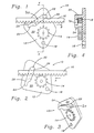
- the gear damper 10 includes actuating means for causing an openable object such as a glove compartment door to be gently or smoothly opened at a dampened or controlled rate of speed in a first direction and to be closed at an undampened rate of speed in a second direction.
- the gear damper 10 is comprised of a pivotable bracket 12 or support means having a toothed driven gear 14 of a rotary damper mounted thereon and a gear rack 16.
- a pivotable bracket 12 When the openable object is a glove compartment door, one end of the gear rack 16 is fixedly attached to a wall of the glove compartment door.
- the pivotal bracket 12 is pivotally attached at a pivot point such as aperture 18 to a stationary wall on the side of the glove compartment which is mounted in a dashboard of an automotive vehicle (not shown). It should be understood to those skilled in the art that the gear rack 16 may be alternatively mounted to the stationary wall of the glove compartment while the pivotal bracket 12 is mounted to the wall of the glove compartment door.
- the pivotal bracket 12 is moulded from a plastics or other suitable material and has a generally quadrilateral configuration.
- the pivotal bracket 12 includes a flat top surface 20 which has attached thereto the toothed driven gear 14. Also, there is provided on the top surface 20 both a guide pin 22 and a cam member 24.
- the gear rack 16 is shown to be substantially straight, it should be understood to those skilled in the art that the gear rack 16 can be formed of a flexible material so as to be wound and unwound in a spiral configuration, thereby occupying a smaller amount of space.
- the gear rack 16 is preferably formed of a relatively soft plastics material or the like.
- the construction of the rotary damper does not form any part of the present invention and may be formed of a conventional nature similar to the type shown in US-A-4691811 because the present invention merely utilizes and co-operates with the toothed driven gear of said rotary damper.
- the guide pin 22 is formed integrally with and protrudes from the top surface 20 of the pivotal bracket 12. Further, the guide pin 22 is of a generally rectangular construction and includes an arcuate bottom surface 26.
- the cam member 24 is of an arcuate-shaped configuration and includes a convex top surface 28.
- the cam member 24 is also formed integrally with and protrudes from the top surface 20 of the pivotal bracket 12. It can be seen that the guide pin 22 is provided adjacent the upper end of the pivotal bracket 12 and that the pivot aperture 18 is formed adjacent the opposite lower end of the pivotal bracket 12. Further, the cam member 24 is formed adjacent the left side of the pivotal bracket 12.
- the free ends of the guide pin 22 and the cam member 24 are shown connected together by a bridge part 30.
- the bridge part 30 can be integrally moulded with the guide pin 22 and the cam member 24 or can be subsequently attached thereto.
- the bridge part 30 acts to keep the gear rack 16 in a desired location against the top surface 20 of the pivotal bracket 12.
- the gear rack 16 will become sandwiched between the arcuate bottom surface 26 of the guide pin 22 and the convex top surface 28 of the cam member 24 so as to maintain the toothed side of the gear rack 16 disengaged from the driven gear 14. Consequently, upon closing of the glove compartment door, no braking force will be applied since the gear rack 16 has been disengaged from the toothed gear 14 so as to close the same at an undampened rate of speed (unrestricted motion).
- the pivotal bracket 12 having the pivot point 18, the guide pin 22 and the cam member 24 function together as actuating means and co-operate with the gear rack 16 so as to cause the glove compartment door to be opened at a dampened rate in the first direction and to be closed at an undampened rate in the second direction.
- the gear damper 10 of the present invention is more compact than those which are traditionally available, thereby eliminating space constraints encountered by the prior art dampening devices, and further, the toothed gear rack 16 is self-aligned with the toothed driven gear 14, thus eliminating any ratcheting and gear skipping problems.
Landscapes
- Engineering & Computer Science (AREA)
- General Engineering & Computer Science (AREA)
- Mechanical Engineering (AREA)
- Transmission Devices (AREA)
- Vibration Dampers (AREA)
- Vehicle Step Arrangements And Article Storage (AREA)
Claims (9)
- Amortisseur à engrenage (10) comprenant un moyen de crémaillère à engrenage (16) adapté à un déplacement entre une première direction (A) et une seconde direction (B), un moyen de console (12) comportant un engrenage mené (14) disposé sur lui pour être en prise avec ledit moyen de crémaillère à engrenage (16), et un moyen amortisseur rotatif amortissant ledit engrenage mené (14) ;
caractérisé en ce que ledit moyen de console (12) est monté de manière à pivoter, et un moyen d'actionnement (22, 24) produisant un amortissement unidirectionnel est disposé sur ledit moyen de console pivotant (12) pour amener ledit moyen de crémaillère à engrenage (16) à être en prise avec ledit engrenage mené (14) afin de produire un mouvement amorti dudit moyen de crémaillère à engrenage (16) dans la première direction (A), et pour amener ledit moyen de crémaillère à engrenage (16) à être dégagé dudit engrenage mené (14) afin de permettre un mouvement non restreint dudit engrenage mené (14) dans la seconde direction (B). - Amortisseur à engrenage selon la revendication 1, caractérisé en ce que ledit moyen d'actionnement comprend une tige de guidage (22) et un organe formant came (24).
- Amortisseur à engrenage selon la revendication 2, caractérisé en ce que ladite tige de guidage (22) comporte une surface inférieure arquée (26).
- Amortisseur à engrenage selon la revendication 2 ou la revendication 3, caractérisé en ce que ledit organe formant came (24) comporte une surface supérieure convexe (28).
- Amortisseur à engrenage selon l'une quelconque des revendications 2 à 4, caractérisé en ce que ladite tige de guidage (22) et ledit organe formant came (24) ont des premières extrémités reliées audit moyen de console pivotant (12) et des secondes extrémités reliées l'une à l'autre par une partie formant pont (30) pour définir une ouverture avec ledit moyen de crémaillère à engrenage (16) s'étendant dans ladite ouverture.
- Amortisseur à engrenage selon l'une quelconque des revendications précédentes, caractérisé en ce que ledit moyen de crémaillère à engrenage (16) est constitué d'une matière plastique souple.
- Amortisseur à engrenage selon l'une quelconque des revendications précédentes, caractérisé en ce que ledit moyen de console pivotant (12) a généralement une configuration de quadrilatère.
- Amortisseur à engrenage selon l'une quelconque des revendications précédentes, caractérisé en ce que ledit moyen de console pivotant (12) comprend une ouverture de pivot (18).
- Amortisseur à engrenage selon l'une quelconque des revendications précédentes, caractérisé en ce que ledit moyen de console pivotant (12) est constitué d'une matière plastique moulée.
Applications Claiming Priority (2)
| Application Number | Priority Date | Filing Date | Title |
|---|---|---|---|
| US08/550,380 US5690194A (en) | 1995-10-30 | 1995-10-30 | One-way pivoting gear damper |
| US550380 | 1995-10-30 |
Publications (2)
| Publication Number | Publication Date |
|---|---|
| EP0771971A1 EP0771971A1 (fr) | 1997-05-07 |
| EP0771971B1 true EP0771971B1 (fr) | 2000-06-21 |
Family
ID=24196937
Family Applications (1)
| Application Number | Title | Priority Date | Filing Date |
|---|---|---|---|
| EP96307394A Expired - Lifetime EP0771971B1 (fr) | 1995-10-30 | 1996-10-10 | Amortisseur pivotant à engrenage |
Country Status (3)
| Country | Link |
|---|---|
| US (1) | US5690194A (fr) |
| EP (1) | EP0771971B1 (fr) |
| DE (1) | DE69608943T2 (fr) |
Families Citing this family (34)
| Publication number | Priority date | Publication date | Assignee | Title |
|---|---|---|---|---|
| US5839548A (en) * | 1995-10-30 | 1998-11-24 | Illinois Tool Works Inc. | Motion control device for rotary dampers |
| DE19729900C1 (de) * | 1997-07-12 | 1998-10-01 | Daimler Benz Ag | Dämpfungseinrichtung |
| FR2803635B1 (fr) * | 2000-01-11 | 2002-04-05 | Gillet Outil | Dispositif de blocage/deblocage du mouvement d'un organe crante, une barre mobile en translation ou un pignon mobile en rotation |
| AT410118B (de) * | 2000-10-19 | 2003-02-25 | Blum Gmbh Julius | Scharnier |
| AT412183B (de) * | 2001-01-25 | 2004-11-25 | Blum Gmbh Julius | Dämpfeinrichtung für bewegbare möbelteile |
| DE10118658A1 (de) * | 2001-04-14 | 2002-10-24 | Itw Automotive Prod Gmbh & Co | Türinnenbetätigung für Automobile |
| KR100640377B1 (ko) * | 2004-03-03 | 2006-10-30 | 삼성전자주식회사 | 휴대용 단말기의 카메라 렌즈 어셈블리 및 그를 구비하는휴대용 단말기 |
| US8145872B2 (en) * | 2004-11-08 | 2012-03-27 | International Business Machines Corporation | Autonomic self-tuning of database management system in dynamic logical partitioning environment |
| JP4785574B2 (ja) * | 2006-03-15 | 2011-10-05 | キヤノン株式会社 | 画像形成装置および開閉機構 |
| KR100750313B1 (ko) * | 2006-11-28 | 2007-08-17 | 현대모비스 주식회사 | 회전형 댐퍼 |
| DE202008000931U1 (de) * | 2008-01-22 | 2009-05-28 | Hettich-Heinze Gmbh & Co. Kg | Dämpfungseinrichtung für bewegbare Möbelteile |
| US9763518B2 (en) | 2014-08-29 | 2017-09-19 | Cisco Technology, Inc. | Systems and methods for damping a storage system |
| US9853873B2 (en) | 2015-01-10 | 2017-12-26 | Cisco Technology, Inc. | Diagnosis and throughput measurement of fibre channel ports in a storage area network environment |
| US9900250B2 (en) | 2015-03-26 | 2018-02-20 | Cisco Technology, Inc. | Scalable handling of BGP route information in VXLAN with EVPN control plane |
| US10222986B2 (en) | 2015-05-15 | 2019-03-05 | Cisco Technology, Inc. | Tenant-level sharding of disks with tenant-specific storage modules to enable policies per tenant in a distributed storage system |
| US11588783B2 (en) | 2015-06-10 | 2023-02-21 | Cisco Technology, Inc. | Techniques for implementing IPV6-based distributed storage space |
| US10778765B2 (en) | 2015-07-15 | 2020-09-15 | Cisco Technology, Inc. | Bid/ask protocol in scale-out NVMe storage |
| US9892075B2 (en) | 2015-12-10 | 2018-02-13 | Cisco Technology, Inc. | Policy driven storage in a microserver computing environment |
| JP6445987B2 (ja) * | 2016-02-11 | 2018-12-26 | 株式会社ニフコ | 車両用収納装置 |
| JP6404247B2 (ja) * | 2016-02-11 | 2018-10-10 | 株式会社ニフコ | 車両用収納装置 |
| US10140172B2 (en) | 2016-05-18 | 2018-11-27 | Cisco Technology, Inc. | Network-aware storage repairs |
| US20170351639A1 (en) | 2016-06-06 | 2017-12-07 | Cisco Technology, Inc. | Remote memory access using memory mapped addressing among multiple compute nodes |
| US10664169B2 (en) | 2016-06-24 | 2020-05-26 | Cisco Technology, Inc. | Performance of object storage system by reconfiguring storage devices based on latency that includes identifying a number of fragments that has a particular storage device as its primary storage device and another number of fragments that has said particular storage device as its replica storage device |
| US11563695B2 (en) | 2016-08-29 | 2023-01-24 | Cisco Technology, Inc. | Queue protection using a shared global memory reserve |
| US10545914B2 (en) | 2017-01-17 | 2020-01-28 | Cisco Technology, Inc. | Distributed object storage |
| US10243823B1 (en) | 2017-02-24 | 2019-03-26 | Cisco Technology, Inc. | Techniques for using frame deep loopback capabilities for extended link diagnostics in fibre channel storage area networks |
| US10713203B2 (en) | 2017-02-28 | 2020-07-14 | Cisco Technology, Inc. | Dynamic partition of PCIe disk arrays based on software configuration / policy distribution |
| US10254991B2 (en) | 2017-03-06 | 2019-04-09 | Cisco Technology, Inc. | Storage area network based extended I/O metrics computation for deep insight into application performance |
| CN110546398B (zh) * | 2017-03-31 | 2021-06-29 | 株式会社利富高 | 单向缓冲机构 |
| US10303534B2 (en) | 2017-07-20 | 2019-05-28 | Cisco Technology, Inc. | System and method for self-healing of application centric infrastructure fabric memory |
| US10404596B2 (en) | 2017-10-03 | 2019-09-03 | Cisco Technology, Inc. | Dynamic route profile storage in a hardware trie routing table |
| US10942666B2 (en) | 2017-10-13 | 2021-03-09 | Cisco Technology, Inc. | Using network device replication in distributed storage clusters |
| US11156025B2 (en) * | 2018-07-05 | 2021-10-26 | Schlage Lock Company Llc | Latchbolt damping module |
| CN114364188B (zh) * | 2022-03-21 | 2022-05-31 | 南通杨天机电设备有限公司 | 一种抗震型5g通信机柜 |
Family Cites Families (9)
| Publication number | Priority date | Publication date | Assignee | Title |
|---|---|---|---|---|
| US1526395A (en) * | 1924-01-26 | 1925-02-17 | James Howard Lesh | Doorcheck |
| US2664183A (en) * | 1951-08-22 | 1953-12-29 | Crompton & Knowles Loom Works | One-way clutch |
| JPS6181244A (ja) * | 1984-09-27 | 1986-04-24 | Kojima Press Co Ltd | 車両用収納体装置における自動突出し装置 |
| JPS61192937A (ja) * | 1985-02-21 | 1986-08-27 | Nifco Inc | 回転ダンパ− |
| JPH0739771B2 (ja) * | 1988-03-31 | 1995-05-01 | 株式会社アルファ | ドアハンドル装置 |
| US4872239A (en) * | 1988-08-10 | 1989-10-10 | The Chamberlain Group, Inc. | Door closure with mechanical braking means |
| JP3280698B2 (ja) * | 1992-05-15 | 2002-05-13 | 株式会社ニフコ | 蓋の開閉装置 |
| JP3304188B2 (ja) * | 1994-02-23 | 2002-07-22 | 株式会社ニフコ | 一方向回転ダンパー |
| JP3124898B2 (ja) * | 1994-09-27 | 2001-01-15 | 日東工器株式会社 | ドアクローザ用流体摩擦抵抗型ダンパー装置 |
-
1995
- 1995-10-30 US US08/550,380 patent/US5690194A/en not_active Expired - Lifetime
-
1996
- 1996-10-10 EP EP96307394A patent/EP0771971B1/fr not_active Expired - Lifetime
- 1996-10-10 DE DE69608943T patent/DE69608943T2/de not_active Expired - Lifetime
Also Published As
| Publication number | Publication date |
|---|---|
| DE69608943D1 (de) | 2000-07-27 |
| DE69608943T2 (de) | 2000-10-19 |
| US5690194A (en) | 1997-11-25 |
| EP0771971A1 (fr) | 1997-05-07 |
Similar Documents
| Publication | Publication Date | Title |
|---|---|---|
| EP0771971B1 (fr) | Amortisseur pivotant à engrenage | |
| EP0828088B1 (fr) | Systèmes d'amortissement unidirectionnels | |
| US20040118851A1 (en) | Receptacle | |
| KR102669649B1 (ko) | 글로브 박스 | |
| JP2001180385A (ja) | 収納ボックス | |
| US6886222B2 (en) | Momentum lockout detented-dampened hinge | |
| US20230212903A1 (en) | Vehicle door device | |
| US5658058A (en) | Floating gear damper | |
| JP7383663B2 (ja) | 車両用収納装置 | |
| JP5016350B2 (ja) | 車両用物入装置 | |
| JP5096724B2 (ja) | 車室内収納ケース | |
| JP2009083727A (ja) | 車両用収納ボックス | |
| KR100412439B1 (ko) | 듀얼 댐퍼를 갖는 힌지 구조 | |
| JP4126777B2 (ja) | 車両のスライドドア構造 | |
| JPH06305365A (ja) | 自動車用収納ボックスの開閉機構 | |
| JP2022184684A (ja) | 収納装置 | |
| JPS6119955Y2 (fr) | ||
| JP4996392B2 (ja) | 蓋体の開き防止装置 | |
| JPS6010911Y2 (ja) | 自動車の変速操作用レバ−装置 | |
| JP4666146B2 (ja) | 跳ね上げ式フード構造 | |
| JP3198348B2 (ja) | 自動車用収納ボックスの開閉機構 | |
| JP2588986Y2 (ja) | 自動車の物入れ装置 | |
| JPH0754532Y2 (ja) | グラブドア用緩衝装置 | |
| JP4126773B2 (ja) | 車両のスライドドア構造 | |
| JP6983742B2 (ja) | アシストグリップ |
Legal Events
| Date | Code | Title | Description |
|---|---|---|---|
| PUAI | Public reference made under article 153(3) epc to a published international application that has entered the european phase |
Free format text: ORIGINAL CODE: 0009012 |
|
| AK | Designated contracting states |
Kind code of ref document: A1 Designated state(s): DE FR GB |
|
| 17P | Request for examination filed |
Effective date: 19971024 |
|
| 17Q | First examination report despatched |
Effective date: 19990319 |
|
| GRAG | Despatch of communication of intention to grant |
Free format text: ORIGINAL CODE: EPIDOS AGRA |
|
| GRAG | Despatch of communication of intention to grant |
Free format text: ORIGINAL CODE: EPIDOS AGRA |
|
| GRAH | Despatch of communication of intention to grant a patent |
Free format text: ORIGINAL CODE: EPIDOS IGRA |
|
| GRAH | Despatch of communication of intention to grant a patent |
Free format text: ORIGINAL CODE: EPIDOS IGRA |
|
| GRAA | (expected) grant |
Free format text: ORIGINAL CODE: 0009210 |
|
| AK | Designated contracting states |
Kind code of ref document: B1 Designated state(s): DE FR GB |
|
| REF | Corresponds to: |
Ref document number: 69608943 Country of ref document: DE Date of ref document: 20000727 |
|
| ET | Fr: translation filed | ||
| PLBE | No opposition filed within time limit |
Free format text: ORIGINAL CODE: 0009261 |
|
| STAA | Information on the status of an ep patent application or granted ep patent |
Free format text: STATUS: NO OPPOSITION FILED WITHIN TIME LIMIT |
|
| 26N | No opposition filed | ||
| REG | Reference to a national code |
Ref country code: GB Ref legal event code: IF02 |
|
| PGFP | Annual fee paid to national office [announced via postgrant information from national office to epo] |
Ref country code: DE Payment date: 20091028 Year of fee payment: 14 |
|
| PGFP | Annual fee paid to national office [announced via postgrant information from national office to epo] |
Ref country code: GB Payment date: 20091026 Year of fee payment: 14 Ref country code: FR Payment date: 20091029 Year of fee payment: 14 |
|
| GBPC | Gb: european patent ceased through non-payment of renewal fee |
Effective date: 20101010 |
|
| PG25 | Lapsed in a contracting state [announced via postgrant information from national office to epo] |
Ref country code: FR Free format text: LAPSE BECAUSE OF NON-PAYMENT OF DUE FEES Effective date: 20101102 |
|
| REG | Reference to a national code |
Ref country code: FR Ref legal event code: ST Effective date: 20110630 |
|
| PG25 | Lapsed in a contracting state [announced via postgrant information from national office to epo] |
Ref country code: GB Free format text: LAPSE BECAUSE OF NON-PAYMENT OF DUE FEES Effective date: 20101010 |
|
| REG | Reference to a national code |
Ref country code: DE Ref legal event code: R119 Ref document number: 69608943 Country of ref document: DE Effective date: 20110502 |
|
| PG25 | Lapsed in a contracting state [announced via postgrant information from national office to epo] |
Ref country code: DE Free format text: LAPSE BECAUSE OF NON-PAYMENT OF DUE FEES Effective date: 20110502 |