EP0771999A2 - Système de rails en très basse tension pour éclairage - Google Patents
Système de rails en très basse tension pour éclairage Download PDFInfo
- Publication number
- EP0771999A2 EP0771999A2 EP96114948A EP96114948A EP0771999A2 EP 0771999 A2 EP0771999 A2 EP 0771999A2 EP 96114948 A EP96114948 A EP 96114948A EP 96114948 A EP96114948 A EP 96114948A EP 0771999 A2 EP0771999 A2 EP 0771999A2
- Authority
- EP
- European Patent Office
- Prior art keywords
- low
- inner part
- voltage
- voltage busbar
- shaped
- Prior art date
- Legal status (The legal status is an assumption and is not a legal conclusion. Google has not performed a legal analysis and makes no representation as to the accuracy of the status listed.)
- Withdrawn
Links
Images


Classifications
-
- H—ELECTRICITY
- H01—ELECTRIC ELEMENTS
- H01R—ELECTRICALLY-CONDUCTIVE CONNECTIONS; STRUCTURAL ASSOCIATIONS OF A PLURALITY OF MUTUALLY-INSULATED ELECTRICAL CONNECTING ELEMENTS; COUPLING DEVICES; CURRENT COLLECTORS
- H01R25/00—Coupling parts adapted for simultaneous co-operation with two or more identical counterparts, e.g. for distributing energy to two or more circuits
- H01R25/14—Rails or bus-bars constructed so that the counterparts can be connected thereto at any point along their length
- H01R25/142—Their counterparts
-
- H—ELECTRICITY
- H01—ELECTRIC ELEMENTS
- H01R—ELECTRICALLY-CONDUCTIVE CONNECTIONS; STRUCTURAL ASSOCIATIONS OF A PLURALITY OF MUTUALLY-INSULATED ELECTRICAL CONNECTING ELEMENTS; COUPLING DEVICES; CURRENT COLLECTORS
- H01R25/00—Coupling parts adapted for simultaneous co-operation with two or more identical counterparts, e.g. for distributing energy to two or more circuits
- H01R25/14—Rails or bus-bars constructed so that the counterparts can be connected thereto at any point along their length
- H01R25/147—Low voltage devices, i.e. safe to touch live conductors
-
- H—ELECTRICITY
- H02—GENERATION; CONVERSION OR DISTRIBUTION OF ELECTRIC POWER
- H02G—INSTALLATION OF ELECTRIC CABLES OR LINES, OR OF COMBINED OPTICAL AND ELECTRIC CABLES OR LINES
- H02G5/00—Installations of bus-bars
- H02G5/02—Open installations
-
- H—ELECTRICITY
- H01—ELECTRIC ELEMENTS
- H01R—ELECTRICALLY-CONDUCTIVE CONNECTIONS; STRUCTURAL ASSOCIATIONS OF A PLURALITY OF MUTUALLY-INSULATED ELECTRICAL CONNECTING ELEMENTS; COUPLING DEVICES; CURRENT COLLECTORS
- H01R25/00—Coupling parts adapted for simultaneous co-operation with two or more identical counterparts, e.g. for distributing energy to two or more circuits
- H01R25/16—Rails or bus-bars provided with a plurality of discrete connecting locations for counterparts
- H01R25/161—Details
- H01R25/162—Electrical connections between or with rails or bus-bars
Definitions
- the present invention relates to a low-voltage busbar system for luminaires, in particular a low-voltage busbar system comprising low-voltage busbars made up of two parallel strip-shaped conductive outer layers and an insulating layer arranged between them, connecting devices for luminaires or the like, fastening devices for fastening the low-voltage busbars to ceilings or walls and connecting devices for the connection of low-voltage busbars to one another.
- a low-voltage busbar system of the aforementioned type generally has flexible low-voltage busbars due to the small thickness of the outer layers and is known, for example, from DE 41 24 066 A1.
- two low-voltage busbars are connected in that their ends are inserted into an elongate sleeve which overlaps the ends of both busbars in one end region and is electrically conductive on one side.
- the sleeve is screwed together after insertion of the end regions of the busbars, resulting in an electrically conductive connection between the respective conductive outer layers of the two low-voltage busbars.
- connection sleeve a complex part to manufacture, which additionally requires a larger assembly effort, namely the insertion of the busbars and the compression of the sleeve by screws. Furthermore, the sleeve mentioned does not allow the joining of three or more busbars in one place.
- the problem underlying the present invention is the creation of a low-voltage busbar system for luminaires of the aforementioned type, which has easy-to-manufacture and assemble connections with high strength, negligible voltage drops and a small bending moment, the connection area of two interconnected low-voltage busbars additionally having an appealing exterior.
- the connecting devices are realized in that the conductive outer layers at the ends of the low-voltage busbars are each bent outward by approximately 90 °, so that there are two connecting surfaces at each end of a low-voltage busbar, which connect to the two corresponding connecting surfaces a further low-voltage busbar can be applied, the connecting surfaces of low-voltage busbars to be connected to one another being secured to one another by suitable fastening means.
- the bends of the outer layers are very easy to manufacture in terms of production technology, the connecting surface preferably being provided with a central bore.
- a connection between two low-voltage busbars can then be realized in that the connecting surfaces are placed against one another and screws are pushed through the holes so that the bent ends of the low-voltage busbars are pressed against one another with nuts screwed thereon.
- the flexibility of the low-voltage busbars is in no way impaired by the screwed-over bent end pieces of the outer layers, so that the straight pieces known from the prior art do not appear in two interconnected arches in the connection according to the invention.
- the fastening means are designed as clamps which can be pushed onto the low-voltage busbars to be connected to one another.
- the brackets can replace the screws and holes and allow an even easier connection.
- the low-voltage busbar system further comprises cladding bodies, which can optionally surround a connecting device, a fastening device or a connecting device.
- the connecting devices are clad so that they are optically inserted into the overall picture of the low-voltage busbar system.
- the cladding bodies advantageously comprise a preferably cylindrical sleeve with at least one receptacle for the low-voltage busbar and a cap that can be screwed or snapped onto the sleeve.
- An insulating inner part with a collar which rests in the receptacle such that there is no electrically conductive connection between the outer layers and the sleeves when the low-voltage busbar is located in the receptacle, can preferably be inserted into the sleeve.
- the insulating inner part can be designed, for example, as a connecting device with bow-shaped contact elements arranged in the inner part and projecting into the receptacle.
- the receptacle in the form of a gap crossing the inner part with an approximately rectangular cross-section corresponding to the cross section of the low-voltage busbar is preferably excluded, the gap-shaped receptacle extending downward from the top of the inner part.
- the bow-shaped contact elements each have a curved, strip-shaped part which, after the bow-shaped contact elements have been inserted into the inner part, projects somewhat into the receptacle with its bend from the outside, so that a low-voltage busbar located in the receptacle each has the bent, strip-shaped parts one side is contacted.
- the bow-shaped contact elements which can be connected to the leads are thus arranged in the inner part in such a way that the low-voltage busbar projecting through the receptacle is automatically contacted by the curved strip-shaped parts.
- two opposite gaps extend from both sides of the receptacle, approximately perpendicular to the longitudinal direction of the receptacle, in the inner part, which have an extension from the top of the inner part to the underside of the receptacle, with a little of the receptacle set back outside in each of the gaps two cuboidal formations are arranged, which extend from slightly below the top of the inner part to the underside of the receptacle and thus form a shoulder in the gap, with an intermediate space remaining free between the formations.
- the curved strip-shaped part of the bow-shaped contact element is adjoined at the top by an approximately right-angled bend, which after the Pushing the bow-shaped contact element into the inner part rests on the shoulder formed by the formations and the curved, strip-shaped part adjoining it at the bottom on the side of the formations facing the receptacle partially abuts against it and partially protrudes somewhat into the receptacle.
- the bow-shaped contact elements can therefore be inserted quickly and easily into the inner part from above and are automatically in the correct position in order to contact the low-voltage busbar due to the support of the bend on the shoulder in the inner part.
- a feed line can be led upwards from the opening between the projections in the gap, preferably from an opening provided in the lower region of the inner part.
- an approximately central bore is arranged in the bend of the bow-shaped contact element and an annular sleeve with a threaded hole penetrating it is fastened above the bend, one in the inner part on both sides in the area of the upper ends of the gaps Bore is provided, which allows screwing a screw from outside the inner part into the threaded bore of the bow-shaped contact element inserted into the inner part.
- the leads which are passed upwards between the projections, preferably stripped at their ends, can be passed through the central bore in the bend and the annular sleeve.
- the screw is then screwed through the inner part into the threaded bore of the annular sleeve, so that the screw fixes the stripped ends of the leads in the annular sleeve.
- the gap extending outward from the receptacle widens shortly before its end to a slot parallel to the receptacle, with the bend of the bow-shaped contact element extending upwards extends portion with an approximately square plan, which is located after insertion of the bow-shaped contact element into the inner part in the slot, in the section with an approximately square plan, a tab is formed, which is located in the section in the slot towards the end of the gap protrudes outwards.
- the preferably stripped ends of the leads, which protrude upward between the formations, can be clamped between the end wall of the gap and the tab by the tab.
- the leads are thus automatically contacted and fixed, so that only the ends of the leads projecting beyond the top of the inner part are cut off have to.
- a collar surrounds the receptacle on the outside of the inner part in such a way that a sleeve which is pushed onto the inner part from below and has a shape which approximately corresponds to the inner part is flush with the collar.
- the sleeve gives the connecting device, together with a cap, a rounded exterior, the openings of the receptacle also being optically closed by the flush collar.
- the partially conductive areas of the inner part such as the fastenings of the bow-shaped contact elements, are shielded by the sleeve and the cap.
- the covering of a connecting device can be realized in that the connecting area of two or more interconnected low-voltage busbars can be inserted into an insulating inner part.
- the connection area is electrically insulated from the outer, preferably metallic, housing by the collar arranged in the inner part.
- the sleeve can, for example, with a fastening device for fastening be connected to a ceiling or to a wall, so that the sleeve with the inner part serves at the same time, for example, as a ceiling suspension for the low-voltage busbar and as a covering for the connection region, for example, of two low-voltage busbars.
- the low-voltage busbar system further comprises electrically conductive contact blocks which have threaded holes on at least two adjacent flat side surfaces, so that the connecting surface of a low-voltage busbar can be fastened to one of these side surfaces by means of a screw.
- the two connection surfaces of the end of a low-voltage busbar can, for example, be screwed onto two contact blocks which are located next to one another and are insulated from one another. Connection surfaces of two further low-voltage busbars can in turn be screwed onto the second side surfaces of the contact blocks with threaded bores.
- the two remaining connecting surfaces of the two further low-voltage busbars can each be screwed to a third and a fourth contact block, which are connected crosswise to the first two contact blocks by cables or the like.
- two, three, four or more low-voltage busbars can be electrically conductively connected to one another by a corresponding number of contact blocks, so that each of the conductive outer layers of a low-voltage busbar is connected to one of the two conductive outer layers of each of the other low-voltage busbars.
- contact blocks are arranged electrically insulated from one another approximately in the corners of a square, two side surfaces of each of the contact blocks equipped with threaded bores being directed outwards, and diagonally opposite contact blocks being electrically conductively connected to one another by means of a cable or another suitable connecting means.
- Contact blocks arranged in this way can be connected to one another in an electrically conductive manner up to four low-voltage busbars tapering perpendicularly towards one another in the form of a cross.
- the sleeves pushed over the connection area of the low-voltage busbars have four cross-shaped slots through which the low-voltage busbars can be guided into the interior of the sleeve. If only two or three low-voltage busbars are to be connected to one another, the correspondingly free slots can be blocked with blind pieces that can be inserted into them. In this way, the same sleeve can be used for covering the connection area of two, three or four interconnected low-voltage busbars.
- the cladding body comprises two ring-shaped sleeve parts which can be placed next to one another and two caps which can be placed thereon, and a cup-shaped insulating inner part which can be pushed into the sleeve parts, wherein a threaded rod which is aligned axially in the cladding body is provided, with the aid of which the sleeve parts, the caps and the pot-shaped insulating inner part can be fixed to one another.
- the sleeve parts and the cup-shaped insulating inner part each have four mutually corresponding rectangular slots which are open on one side and are each arranged at angular intervals of 90 ° to one another.
- a ring is advantageously used as the connecting means for every two contact blocks used, on which the two contact blocks are fastened radially on opposite sides of its central bore and spaced apart from it.
- the contact blocks are preferably of approximately prismatic design, the sides of the contact blocks which rest against the ring and whose sides face away from the ring have the shape of an isosceles right-angled triangle, the surfaces of the contact blocks which are located radially opposite one another on different sides of the central bore, the connecting surfaces between the hypothenuses of the are isosceles right-angled triangles, and wherein the projecting from the ring outwardly, provided with threaded holes for screwing the low-voltage busbar side surfaces of the contact blocks are the connecting surfaces between the cathets of the isosceles right-angled triangles.
- the threaded bores for screwing on the low-voltage busbars are arranged somewhat eccentrically on the corresponding side surfaces of the contact blocks in the direction of the sides of the contact blocks opposite the sides lying against the ring.
- an approximately cube-shaped insulating inner part is provided for holding the two rings with the two contact blocks attached to them in the cladding body, to which the two rings can be placed from two opposite sides of the inner part so that the four contact blocks connected to the rings with their Connection surfaces between the hypotenuses of the triangles on the outer sides of the approximately cube-shaped insulating inner part are each offset by 90 ° relative to one another in a rotationally fixed manner, the contact blocks arranged next to one another being electrically insulated from one another.
- the approximately cube-shaped insulating inner part has a through hole which penetrates the side faces of the inner part which can be placed on the rings in the center, the inner diameter of the hole roughly corresponding to the outer diameter of the threaded rod axially aligned in the casing body.
- the approximately cube-shaped insulating inner part points to the two to the rings that can be placed on the rings each have a tubular extension surrounding the bore, onto each of which a ring with the contact blocks fastened on the inner part side can be pushed in a form-fitting manner.
- mutually opposite rounded formations are arranged, which end with the surfaces of the side surfaces that can be placed on the rings and whose expansion is approximately that which protrudes over the cube-shaped base body of the insulating inner part between the two Corresponding sections of the sections of the ring pushed onto one of the lugs corresponds, the thickness of the formations corresponding approximately to the thickness of the rings, and wherein the formations arranged on the opposite side surfaces are offset by 90 ° from one another.
- a total of four low-voltage busbars can be screwed onto the outer sides of the contact blocks lying against the cube-shaped insulating inner part.
- the approximately cube-shaped insulating inner part with the low-voltage busbar ends attached thereto can be pushed into the casing body by pushing onto the threaded rod, the ends of the low-voltage busbars projecting through the slots recessed in the sleeve part and the pot-shaped insulating inner part .
- the casing body surrounds the connection area of the four low-voltage busbars in a stable manner.
- the described preferred embodiment of the cladding body represents a particularly stable and at the same time quick and easy to assemble and disassemble embodiment.
- the lugs of the cube-shaped insulating inner part result in a stable mounting of the low-voltage busbars in the cladding body.
- the formations on the two side surfaces that can be placed on the rings increase the stability of the support of the rings on the side surfaces.
- they provide additional insulation between the ring and the contact blocks protruding from the other side and fastened to the other ring.
- the arrangement of the threaded holes for the attachment of the low-voltage busbars about the thickness of the rings ensures that the threaded holes are located of contact blocks attached to different rings after sliding the two rings onto the opposite lugs of the approximately cube-shaped insulating inner part at the same height. This enables a low-voltage busbar to be easily attached to the contact blocks.
- the low-voltage busbars 1 comprise two strip-shaped conductive outer layers 2, for example made of brass sheet, and an insulating layer 3 located between them, which can be implemented, for example, by double-sided adhesive tape.
- the low-voltage busbars 1 are flexible due to the small thickness of the outer layers 2.
- the conductive outer layers have, in their end region, narrow connecting surfaces 4 bent by 90 °, which, in accordance with the embodiment according to FIGS. 1a and 1b, are provided with an approximately central bore 5.
- the connecting surfaces 4 of two low-voltage busbars 1 to be connected to one another are placed so that the respective bores 5 overlap.
- the connecting surfaces 4 can be screwed together so that a conductive connection between the corresponding strip-shaped conductive outer layers 2 of the low-voltage busbars 1 comes about.
- a toothed lock washer 7a see FIG. 2c can be placed in order to increase the strength of the connection.
- the connecting surfaces 4 have no bores 5.
- the connection is made by pushing a clip onto the pressed-together connecting surfaces 4.
- connection area of two interconnected low-voltage busbars 1 can be covered by a cladding body 9.
- the lining body 9 comprises a sleeve 10, which is preferably made of the material of the conductive outer layers 2.
- a cap 11 can be screwed or snapped onto the sleeve 10 from above.
- the sleeve 10 has approximately the shape of a hollow cylinder with a bottom surface protruding downward in the form of a cap and a receptacle 12 with a rectangular cross section into which the low-voltage busbars 1 can be inserted from above.
- An insulating inner part 13 is inserted into the sleeve 10 and has a collar 14 which rests in the recess 12 in such a way that the low-voltage busbar inserted therein does not come into electrically conductive contact with the metallic sleeve 10.
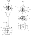
- the covering body 15 shown in FIGS. 3a and 3b has an approximately cylindrical sleeve 16 with a conically tapering end piece 17. From the conical end piece 17, a ceiling suspension element 18 fastened to the covering body 15 is led upwards. A cap 19 can be screwed or snapped onto the sleeve 16.
- the covering body 20 shown in FIGS. 4a and 4b likewise has a sleeve 16 with a conically tapering end piece 17 and a cap 19 which can be screwed onto the sleeve 16.
- a radiator 21 is connected to the covering body 20.
- a corresponding radiator fastening element 22 is led out of the conically tapering end piece 17.
- the inner part 23 located inside the sleeve 16 has resilient bow-shaped contact elements 24 which protrude into the receptacle 12 and which, when the low-voltage busbar 1 is pushed into the receptacle 12, make electrical contact with their conductive outer layers 2 and pass on the tapped voltage to the radiator via the leads 25.
- the connecting device formed by the inner part 23 and the bow-shaped contact elements 24 can also be connected to a voltage supply via the feed lines 25 and thus enable current to be fed into the low-voltage busbar system.
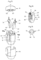
- the receptacle 12 is somewhat radially outward set back two projections 61 arranged in the gap 58, which thus form a shoulder slightly below the top of the inner part 23.
- the two projections 61 each leave a space between them which corresponds approximately to their thickness in the direction of the recess 12.
- the inner part 23 also has an external thread 62 at its upper end.
- a collar 14 then surrounds the receptacle 12 on the underside of the external thread 62, which ends flush with the sleeve 16 pushed onto the inner part 23, as can be seen from the sleeve 16 surrounding the inner part 23 in broken lines in FIG. 10.
- the bow-shaped contact element 24 can be inserted into the inner part 23 from above.
- the bow-shaped contact element 24 has a strip-shaped, approximately rectangular lower part 63, which is bent in its longitudinal direction, so that the central section protrudes somewhat outwards.
- the lower part 63 has a right-angled bend 64 at its upper end, which extends backwards from the outwardly bent side.
- the bend 64 merges into a section 65 that extends vertically upward and has an approximately square outline.
- a likewise approximately square tab 66 is punched out in the middle of this approximately square section 65 and extends backward from the square section 65 away from the strip-shaped section 63.
- the right-angled bend 64 rests on the shoulder formed by the projections 61.
- the strip-shaped lower part 63 of the bow-shaped contact element 24 extends along the projections 61 from their upper edge to the underside of the receptacle 12, the strip-shaped lower part 63 protruding somewhat into the receptacle 12 with its central section due to its bending. This ensures that a low-voltage busbar 1 located in the receptacle 12 is securely contacted by the lower part 63.
- the approximately square section 65 of the bow-shaped contact element 24 rests after insertion into the inner part 23 in the slot 59, the tab 66 pressing and holding the stripped end of the lead 25 into the recess 60 so that it can no longer slip.
- the upper ends of the feed lines 25 projecting beyond the upper side of the inner part 23 can be cut off.
- the sleeve 16 can then be pushed onto the inner part 23 from below.
- the cap 19 with its internal thread 67 can be screwed onto the external thread 62 of the inner part 23, so that the lower edge of the cap 19 abuts the upper edge of the sleeve 16 and a base 68 arranged in the center of the cap 19 on the upper side of the low-voltage busbar 1 lies on.
- connection device is shown in FIGS. 13 to 15.
- a radially outward gap 69 is provided, on the upper end of which is opposite the receptacle 12, a radial bore 70 is arranged.
- two projections 61 are set back from the central receptacle 12 in a slightly radially outward direction in the gap 69, which form a shoulder for the support of the bend 64 of the bow-shaped contact element 24.
- the from the rear end of the bend 64 protrudes vertically upward.
- annular sleeve 72 is fastened approximately centrally on the bend 64 and has a threaded bore 73 on its side facing away from the strip-shaped lower part 63.
- the bend 64 of the bow-shaped contact element 24 is drilled below the central opening of the annular sleeve 72, so that the angled end of the lead 25 can be pushed through the bend 64 and the annular sleeve 72.
- the stripped ends of the leads 25 can be fixed in the annular sleeves 72 by screws 71, which can be screwed through the bores 70 in the inner part 23 into the threaded bores 73 of the bow-shaped contact elements 24 inserted into the inner part 23.
- each of the low-voltage busbars 1 makes contact with a contact block 27 with each of its two connecting surfaces 4.
- Each two diagonally opposite contact blocks 27 are electrically conductively connected to one another by means of a cable 29. This ensures that each of the conductive outer layers 2 of a low-voltage busbar is connected to one of the two conductive outer layers 2 of each of the other low-voltage busbars 1.
- the sleeve 30 surrounding this connection area can be connected, for example, to a ceiling suspension element 18, a cap 31 being screwable onto the sleeve 30.
- the sleeve 30 has four opposing rectangular slots 32 which are open at the bottom and into which the four low-voltage busbars 1 can be inserted.
- the four slots 32 thus form two intersecting receptacles for the low-voltage busbars 1, which correspond to the receptacles 12.
- An insulating inner part 33 with a collar 34 can be inserted into the sleeve 30, which surrounds the low-voltage busbars inserted into the slots 32 such that the sleeve 30th is electrically isolated from the low-voltage busbars 1.
- FIGS. 7 to 9 an alternative embodiment to the covering body 26 in FIGS. 5a and 5b of a covering body 36 surrounding the connection area of four interconnected low-voltage busbars 1 is shown.
- four electrically conductive, approximately prism-shaped contact blocks 37 are arranged so as to be electrically insulated from one another approximately in the corners of a square.
- the top and bottom of each of the contact blocks 37 has approximately the shape of an isosceles right triangle.
- the outwardly directed, approximately square sides of the contact blocks 37 each form the connecting surfaces between the cathets of the isosceles right-angled triangles.
- each of the contact blocks 37 has threaded bores 38 on its outward-facing surfaces, into which the screws 6 pushed through the bores 5 of the connecting surfaces 4 can be screwed for fastening the low-voltage busbars 1. 5 contacted in this way each of the low-voltage busbars 1 has a contact block 37 with each of its two connecting surfaces 4.
- FIGS. 9a and 9b diagonally opposite contact blocks 37 are connected to one another by means of an electrically conductive ring 39.
- a plastic inner part 40 which can be seen in FIGS. 8a to 8c, is provided, which has an essentially cube-shaped shape.
- a tubular molding 41 is attached, the outer diameter of which corresponds approximately to the inner diameter of the rings 39.
- upper and lower rounded projections 42, 43 are attached to the plastic inner part 40.
- the upper projections 42 lie opposite one another and in Fig. 8c protrude from the approximately cube-shaped plastic inner part 40 to the left and right.
- the lower projections 43 also lie opposite one another and are offset by 90 ° with respect to the upper projections 42, so that they protrude forwards and backwards in Fig. 8c from the approximately cube-shaped plastic inner part and to the left and right in Fig. 8b from the plastic inner part stick out.
- the shape of the plastic inner part 40 ensures that a ring 39 with two contact blocks 37 can be pushed onto the plastic inner part 40 from above and from below, one ring 39 enclosing a tubular molding 41 and the two inner sides of a ring 39 interconnected contact blocks 37 rest on two opposite outer sides of the approximately cube-shaped plastic inner part.
- the rounded projections 43, 43 form a support for the sections of the rings 39 located between the contact blocks 37.
- the cladding body 36 is composed of an upper and a lower annular sleeve part 44, 45 and an upper and a lower cap 46, 47.
- the sleeve parts 44, 45 and the caps 46, 47 can preferably be made from the material of the conductive outer layers 2 of the low-voltage busbars 1.
- a pot-shaped insulating inner part 48 can be inserted into the annular sleeve parts 44, 45 and has a threaded bore 49 in the center of its pot base.
- a threaded rod 50 can be screwed into the threaded bore 49, which protrudes on the upper side through a central bore arranged in the upper cap 46 and on the lower end of which the lower cap 47 can be screwed with a threaded bore 51 cut into the center.
- the disk-shaped lower cap 47 has a lower conical projection 52, into which the threaded bore 51 partially projects from above.
- a ring 53 with an internal thread can be screwed onto the threaded rod 50 on the upper side of the upper cap 46 in order to hold together the sleeve parts 44, 45 forming the covering body 36 and the caps 46, 47.
- the sleeve parts 44, 45 each have four mutually opposite rectangular slits 54 which are open at the bottom and at the top and into which the four low-voltage busbars 1 can be inserted.
- the four slots 54 thus form slots corresponding to the slots 32 for the low-voltage busbars 1.
- the cup-shaped insulating inner part 48 likewise has four opposing rectangular slots 55 which are open on one side and through which the low-voltage busbars 1 projecting through the slots 54 can also protrude. 5, the pot-shaped insulating inner part 48 can have a collar 57 which surrounds the slots 54 in such a way that the sleeve parts 44, 45 are electrically insulated from the low-voltage busbars 1.
- the inner plastic part 40 has a continuous bore 56, the inner diameter of which corresponds approximately to the outer diameter of the threaded rod 50, so that the inner plastic part can be pushed onto the threaded rod 50.
- the threaded holes 38 in the outwardly facing surfaces of the contact blocks 37 are each off-center on the Outside of the contact blocks arranged that the centers of the threaded holes 38 are from above and below by means of the rings 39 on the plastic inner part 40 pushed contact blocks at the same height. In this way, the connecting surfaces 4 of a low-voltage busbar 1 can be screwed onto two outer sides of two contact blocks 37 located in the same plane.
- the four ends of four low-voltage busbars 1 fastened in this way to the contact blocks 37 can be inserted into the casing body 36 together with the plastic inner part carrying the contact blocks 37 after removal of the lower cap 47 and the lower annular sleeve part 45, the plastic inner part 40 having the continuous one Bore 46 is pushed onto the threaded rod 50 and the ends of the low-voltage busbars 1 protrude through the slots 54, 55.
- the plastic inner part 40 and thus the ends of the low-voltage busbars 1 connected to it are firmly held in the casing body 36.
- an insulating cover plate 58 can be inserted with the aid of a nut 59. This increases the stability of the holder of the plastic inner part 40.
- a ceiling suspension element 18, for example, can be screwed onto the upper end of the threaded rod 50 protruding from the upper cap 46 and the screw-on ring 53.
- FIGS. 7 to 9 can also be used in the case of a T-shaped connection of three low-voltage busbars and in the case of an L-shaped connection of two low-voltage busbars 1, the unused rectangular slots 32 then being used in each case , 54 are blocked by a blind piece which can be inserted therein.
Landscapes
- Suspension Of Electric Lines Or Cables (AREA)
- Connections Effected By Soldering, Adhesion, Or Permanent Deformation (AREA)
Applications Claiming Priority (6)
| Application Number | Priority Date | Filing Date | Title |
|---|---|---|---|
| DE29517289U | 1995-11-02 | ||
| DE29517289U DE29517289U1 (de) | 1995-11-02 | 1995-11-02 | Anschlußvorrichtung für eine Niedervoltstromschiene |
| DE29518253U DE29518253U1 (de) | 1995-11-17 | 1995-11-17 | Niedervoltstromschienensystem für Leuchten |
| DE29518253U | 1995-11-17 | ||
| DE19615525 | 1996-04-19 | ||
| DE19615525A DE19615525A1 (de) | 1995-11-17 | 1996-04-19 | Niedervoltstromschienensystem für Leuchten |
Publications (2)
| Publication Number | Publication Date |
|---|---|
| EP0771999A2 true EP0771999A2 (fr) | 1997-05-07 |
| EP0771999A3 EP0771999A3 (fr) | 1998-04-29 |
Family
ID=27216159
Family Applications (1)
| Application Number | Title | Priority Date | Filing Date |
|---|---|---|---|
| EP96114948A Withdrawn EP0771999A3 (fr) | 1995-11-02 | 1996-09-18 | Système de rails en très basse tension pour éclairage |
Country Status (1)
| Country | Link |
|---|---|
| EP (1) | EP0771999A3 (fr) |
Cited By (3)
| Publication number | Priority date | Publication date | Assignee | Title |
|---|---|---|---|---|
| DE29713838U1 (de) * | 1997-08-02 | 1998-11-26 | Robert Conradt Meß- und Regeltechnik, 78476 Allensbach | Halogen-Leuchtensystem mit gitterartig gestalteten Stromführungen |
| EP2028731A2 (fr) | 2007-08-18 | 2009-02-25 | Wampfler Aktiengesellschaft | Connecteur de serrage pour une ligne de contact |
| GB2473193A (en) * | 2009-09-02 | 2011-03-09 | Yu-Che Kao | A luminaire |
Family Cites Families (4)
| Publication number | Priority date | Publication date | Assignee | Title |
|---|---|---|---|---|
| JPS4791Y1 (fr) * | 1969-10-16 | 1972-01-06 | ||
| US4195198A (en) * | 1979-01-08 | 1980-03-25 | General Electric Company | Busway ground bus joint |
| DE3516449A1 (de) * | 1985-05-08 | 1986-11-13 | Hailo-Werk Rudolf Loh Gmbh & Co Kg, 6342 Haiger | Niederspannungs-beleuchtungsanordnung |
| DE4124066C2 (de) * | 1991-07-19 | 1997-03-20 | Ind Und Design Licht Inh Domin | Elektrisches Leuchtensystem |
-
1996
- 1996-09-18 EP EP96114948A patent/EP0771999A3/fr not_active Withdrawn
Cited By (4)
| Publication number | Priority date | Publication date | Assignee | Title |
|---|---|---|---|---|
| DE29713838U1 (de) * | 1997-08-02 | 1998-11-26 | Robert Conradt Meß- und Regeltechnik, 78476 Allensbach | Halogen-Leuchtensystem mit gitterartig gestalteten Stromführungen |
| EP2028731A2 (fr) | 2007-08-18 | 2009-02-25 | Wampfler Aktiengesellschaft | Connecteur de serrage pour une ligne de contact |
| EP2028731A3 (fr) * | 2007-08-18 | 2010-07-28 | Conductix-Wampfler AG | Connecteur de serrage pour une ligne de contact |
| GB2473193A (en) * | 2009-09-02 | 2011-03-09 | Yu-Che Kao | A luminaire |
Also Published As
| Publication number | Publication date |
|---|---|
| EP0771999A3 (fr) | 1998-04-29 |
Similar Documents
| Publication | Publication Date | Title |
|---|---|---|
| DE4419055C2 (de) | Chip-Schmelzsicherung | |
| EP0754357B1 (fr) | Systeme de connexion pour conducteurs electriques | |
| EP1129509B1 (fr) | Dispositif de raccordement | |
| DE4125939C2 (de) | Leitende Verbindervorrichtung | |
| DE3135173C2 (de) | Als elektrischer Stecker oder als Steckdose oder als Kupplungsdose ausgebildetes Installationsteil | |
| DE4124066A1 (de) | Elektrisches leuchtensystem | |
| DE4428699A1 (de) | Leitfähige Verbinderanordnung | |
| DE19731411A1 (de) | Haltevorrichtung für elektrische Lüfter, insbesondere Kleinstlüfter | |
| DE10062644C1 (de) | Halter für eine Stromerfassungseinrichtung | |
| EP0685906A1 (fr) | Procédé pour la fabrication d'un appareil électrique et appareil électrique réalisé d'aprés ce procédé | |
| EP0771999A2 (fr) | Système de rails en très basse tension pour éclairage | |
| DE19615525A1 (de) | Niedervoltstromschienensystem für Leuchten | |
| EP0649192A2 (fr) | Dispositif d'installation électrique avec module supplémentaire | |
| EP0568899A2 (fr) | Prise de câble multipolaire | |
| DE19525801C2 (de) | Vorrichtung zum elektrisch leitenden Verbinden von zwei elektrischen Leitungen | |
| DE3909548A1 (de) | Anschlussklemme | |
| DE2538199A1 (de) | Anschlussklemme fuer elektrische leitungen | |
| DE29517289U1 (de) | Anschlußvorrichtung für eine Niedervoltstromschiene | |
| EP1124285A2 (fr) | Prise de courant d'appareils | |
| DE8516807U1 (de) | Einpoliger elektrischer Kontakt | |
| DE3808335C2 (fr) | ||
| DE102006022987B3 (de) | Verbindungselement | |
| DE10005218C2 (de) | Elektrisches Gerät mit Tragelement | |
| DE3743268C2 (fr) | ||
| DE2827143A1 (de) | Vorrichtung zur verriegelung der kontaktelemente fuer elektrische, mehrpolige steckvorrichtungen |
Legal Events
| Date | Code | Title | Description |
|---|---|---|---|
| PUAI | Public reference made under article 153(3) epc to a published international application that has entered the european phase |
Free format text: ORIGINAL CODE: 0009012 |
|
| AK | Designated contracting states |
Kind code of ref document: A2 Designated state(s): AT BE CH DE FR IT LI NL |
|
| PUAL | Search report despatched |
Free format text: ORIGINAL CODE: 0009013 |
|
| AK | Designated contracting states |
Kind code of ref document: A3 Designated state(s): AT BE CH DE FR IT LI NL |
|
| 17P | Request for examination filed |
Effective date: 19980709 |
|
| GRAG | Despatch of communication of intention to grant |
Free format text: ORIGINAL CODE: EPIDOS AGRA |
|
| 17Q | First examination report despatched |
Effective date: 20010716 |
|
| GRAG | Despatch of communication of intention to grant |
Free format text: ORIGINAL CODE: EPIDOS AGRA |
|
| GRAH | Despatch of communication of intention to grant a patent |
Free format text: ORIGINAL CODE: EPIDOS IGRA |
|
| STAA | Information on the status of an ep patent application or granted ep patent |
Free format text: STATUS: THE APPLICATION IS DEEMED TO BE WITHDRAWN |
|
| 18D | Application deemed to be withdrawn |
Effective date: 20020308 |