EP1124285A2 - Prise de courant d'appareils - Google Patents
Prise de courant d'appareils Download PDFInfo
- Publication number
- EP1124285A2 EP1124285A2 EP00126719A EP00126719A EP1124285A2 EP 1124285 A2 EP1124285 A2 EP 1124285A2 EP 00126719 A EP00126719 A EP 00126719A EP 00126719 A EP00126719 A EP 00126719A EP 1124285 A2 EP1124285 A2 EP 1124285A2
- Authority
- EP
- European Patent Office
- Prior art keywords
- contact
- cable wire
- socket according
- base body
- device socket
- Prior art date
- Legal status (The legal status is an assumption and is not a legal conclusion. Google has not performed a legal analysis and makes no representation as to the accuracy of the status listed.)
- Granted
Links
- 239000012777 electrically insulating material Substances 0.000 claims abstract description 4
- 238000003780 insertion Methods 0.000 claims description 13
- 230000037431 insertion Effects 0.000 claims description 13
- 239000000428 dust Substances 0.000 claims description 4
- 239000002184 metal Substances 0.000 claims description 3
- 238000009413 insulation Methods 0.000 claims description 2
- 230000002093 peripheral effect Effects 0.000 claims description 2
- 230000013011 mating Effects 0.000 claims 2
- 238000011161 development Methods 0.000 description 3
- 230000018109 developmental process Effects 0.000 description 3
- 238000004519 manufacturing process Methods 0.000 description 3
- 238000010276 construction Methods 0.000 description 2
- 229920003023 plastic Polymers 0.000 description 2
- 239000004952 Polyamide Substances 0.000 description 1
- 230000006978 adaptation Effects 0.000 description 1
- 239000003365 glass fiber Substances 0.000 description 1
- 239000004033 plastic Substances 0.000 description 1
- 229920002647 polyamide Polymers 0.000 description 1
- 230000001681 protective effect Effects 0.000 description 1
- XLYOFNOQVPJJNP-UHFFFAOYSA-N water Substances O XLYOFNOQVPJJNP-UHFFFAOYSA-N 0.000 description 1
Images


Classifications
-
- H—ELECTRICITY
- H01—ELECTRIC ELEMENTS
- H01R—ELECTRICALLY-CONDUCTIVE CONNECTIONS; STRUCTURAL ASSOCIATIONS OF A PLURALITY OF MUTUALLY-INSULATED ELECTRICAL CONNECTING ELEMENTS; COUPLING DEVICES; CURRENT COLLECTORS
- H01R4/00—Electrically-conductive connections between two or more conductive members in direct contact, i.e. touching one another; Means for effecting or maintaining such contact; Electrically-conductive connections having two or more spaced connecting locations for conductors and using contact members penetrating insulation
- H01R4/24—Connections using contact members penetrating or cutting insulation or cable strands
- H01R4/2416—Connections using contact members penetrating or cutting insulation or cable strands the contact members having insulation-cutting edges, e.g. of tuning fork type
- H01R4/2445—Connections using contact members penetrating or cutting insulation or cable strands the contact members having insulation-cutting edges, e.g. of tuning fork type the contact members having additional means acting on the insulation or the wire, e.g. additional insulation penetrating means, strain relief means or wire cutting knives
-
- H—ELECTRICITY
- H01—ELECTRIC ELEMENTS
- H01R—ELECTRICALLY-CONDUCTIVE CONNECTIONS; STRUCTURAL ASSOCIATIONS OF A PLURALITY OF MUTUALLY-INSULATED ELECTRICAL CONNECTING ELEMENTS; COUPLING DEVICES; CURRENT COLLECTORS
- H01R13/00—Details of coupling devices of the kinds covered by groups H01R12/70 or H01R24/00 - H01R33/00
- H01R13/02—Contact members
- H01R13/35—Contact members for non-simultaneous co-operation with different types of contact member, e.g. socket co-operating with either round or flat pin
-
- H—ELECTRICITY
- H01—ELECTRIC ELEMENTS
- H01R—ELECTRICALLY-CONDUCTIVE CONNECTIONS; STRUCTURAL ASSOCIATIONS OF A PLURALITY OF MUTUALLY-INSULATED ELECTRICAL CONNECTING ELEMENTS; COUPLING DEVICES; CURRENT COLLECTORS
- H01R4/00—Electrically-conductive connections between two or more conductive members in direct contact, i.e. touching one another; Means for effecting or maintaining such contact; Electrically-conductive connections having two or more spaced connecting locations for conductors and using contact members penetrating insulation
- H01R4/28—Clamped connections, spring connections
- H01R4/30—Clamped connections, spring connections utilising a screw or nut clamping member
- H01R4/36—Conductive members located under tip of screw
- H01R4/363—Conductive members located under tip of screw with intermediate part between tip and conductive member
-
- H—ELECTRICITY
- H01—ELECTRIC ELEMENTS
- H01R—ELECTRICALLY-CONDUCTIVE CONNECTIONS; STRUCTURAL ASSOCIATIONS OF A PLURALITY OF MUTUALLY-INSULATED ELECTRICAL CONNECTING ELEMENTS; COUPLING DEVICES; CURRENT COLLECTORS
- H01R13/00—Details of coupling devices of the kinds covered by groups H01R12/70 or H01R24/00 - H01R33/00
- H01R13/02—Contact members
- H01R13/10—Sockets for co-operation with pins or blades
Definitions
- the invention relates to a device socket for manufacture an electrically conductive connection between Electrical components, according to the preamble of the claim 1.
- can Device sockets can be designed very diverse, whereby their contact elements on the one hand firmly with electrical Connection wires are connected and on the other hand electrically conductive with suitable connectors or Device connectors are detachably pluggable.
- the electric conductive contact elements of these known designs are generally in a kind of contact carrier attached from electrically insulating material. Disadvantages of many known embodiments are seen in the fact that they are often proportional are cumbersome and relatively close to others electrical components adapted and firmly mounted with it are.
- the invention has for its object a device socket the prerequisite in the preamble of claim 1 To create a kind that is characterized above all by one relatively simple and robust construction, due to its versatile, variable adaptability to other electrical Components as well as their relatively easy assembly and disassembly and thus by a easy interchangeability.
- each contact element for example in the form of a flat sheet metal strip and in the form a combination contact element is designed in such a way that his first connection contact end on the one hand provided with a cable wire insertion slot Cutting contact and on the other hand one for clamping a contact device assigned to a cable wire end having, cutting contact and contact device can be used optionally.
- the device socket designed in this way is an extremely good prerequisite for this shows that it is used in a very versatile manner and easily interchangeable with the corresponding ones Provide contact elements and other electrical Components can be assembled.
- each contact element in a continuous, appropriate slot in the base body and by an outwardly protruding, bent Fixing tabs axially immovable in the body fixed.
- the device socket according to the invention can in this way relatively easily and quickly with the for the number of contact elements required for each application (e.g. two, three or four contact elements) be equipped. In any case, however, is for it ensured that each contact element is axially immovable is fixed in the base body, so that during manufacture of detachable connector the contact elements be held immovably in the body.
- each contact element provided cutting contact is simple Formed so that the cutting edges provided cable wire slot in the longitudinal direction of the contact element extends to the free end of the first Cutting contact open out and one has the slot width matched to the end of the cable wire, that when longitudinally inserting an associated cable wire end cutting through a cable wire insulation jacket an electrically conductive connection with manufactured the contact element and this cable wire end can be clamped.
- each contact element is designed as an insulating part
- Cable wire hold-down is assigned to the a receiving slot for the protruding from the base body (outstanding) free end section of the first Connection contacts as well as a transverse continuous cable wire insertion opening for receiving of the associated, provided with the insulating jacket Has cable wire end.
- This cable wire hold-down thus also ensures a secure fixing of the corresponding cable wire end in the slot the cutting contact.
- you can all hold downs of the same design also still at the same time as connecting elements to further with the first connection contact ends of the Contact elements connectable electrical components can be used, as will be shown later with some Examples or the drawing can be seen.
- the device socket according to the invention also has all because of their relatively simple structure and their Versatile and variable design and adaptation options the requirements in an extremely advantageous manner for a standard-compliant version.
- This Trap is characterized above all by a standard Arrangement and distribution of the contact elements, through standard-compliant design and main dimensions as well thanks to a dust and moisture-proof standard Execution.
- the device socket according to the invention is - as such known - for the production of an electrically conductive Connection between corresponding electrical components built up.
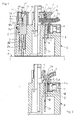
- This device socket is initially based on of Figures 1 and 2 explained in their basic structure.
- Appliance socket essentially an externally approximately Cube-shaped or cuboid housing-like basic body 1, which is a type of contact carrier or contact element carrier forms for several electrically conductive contact elements 2 and a substantially electrically insulating Material is made, for example from a preferably polyamide reinforced with glass fibers (e.g. 30%) (e.g. PA6).
- a substantially electrically insulating Material is made, for example from a preferably polyamide reinforced with glass fibers (e.g. 30%) (e.g. PA6).
- a substantially electrically insulating Material is made, for example from a preferably polyamide reinforced with glass fibers (e.g. 30%) (e.g. PA6).
- a substantially electrically insulating Material is made, for example from a preferably polyamide reinforced with glass fibers (e.g. 30%) (e.g. PA6).
- a maximum of four contact elements 2 in a suitable manner Way set in Fig.1 there are two such Contact elements 2 approximately at right angles to each other around
- connection contact ends 2a, 2b are opposite to each other Ends formed as connection contact ends 2a, 2b.
- first connection contact end 2a that is to say in FIGS. 1 and 2 upper connection contact end 2a, with a cable wire end 3 connectable
- second connection contact end 2b with a in Fig.1 only indicated by dash-dotted counter contact element 4 of a likewise only indicated by dash-dotted lines, suitably trained electrical component 5 can be put together.
- Every contact element 2 expediently points to its - in Figures 1 and 2 - lower second contact end 2b one for free Open, roughly fork-shaped clamp opening 2b 'for receiving the mentioned plug-shaped counter-contact element 4 of the other electrical component 5.
- each contact element 2 of this device socket As a comparison representations in the figures 1 and 2 clearly shows, is each contact element 2 of this device socket according to the invention approximately in shape a flat sheet metal strip and in the form of a combination contact element executed in such a way that his first Terminal contact end 2a one with one Cable wire insertion slot 6 provided cutting contact 7 and on the other hand one for clamping the cable wire end 3 has assigned clamping contact device 8, where cutting contact 7 and terminal contact device 8 can be used optionally as follows explained in more detail with reference to Figures 1 and 2 becomes.
- each contact element 2 in is essentially of the same design and in one matching, continuous receiving slot 9 in the Basic body 1 inserted and inserted in its Position by an outwardly protruding, bent Fixing tabs 9a axially immovable in the base body 1 is fixed (in advance of the explanations to Figures 3 and 4 already mentioned that there which are bent into a suitable recess of the base body 1 Fixing tab 9a can be seen particularly clearly are).
- the terminal contact device 8 for the upper terminal contact end 2a of or each contact element 2 is essentially formed be and can be used.
- This is in the main body 1 each approximately parallel to the / each contact element 2 running, to the outside and to the contact element 2 open cable wire receiving groove 10 is provided.
- the or each terminal contact device 8 has one accommodated in the base body 1, from the outside accessible and in the area of the cable wire receiving groove 10 against a side surface 2c of the contact element 2 screwable screw terminal, which is essentially a Clamping screw 11 with screw head accessible from the outside lla, a non-rotatably held in the base body 1 Screw nut (e.g.
- FIG.1 shows the two rotated approximately at right angles to one another in the base body 1 recorded contact elements 2 simultaneously in two different views.
- right contact element 2 the previously described terminal contact device 8 - without pinched cable wire end - you can see, of course, both or all upper, first connection contact ends 2a in the same way assigned to a terminal contact device 8.
- each contact element 2 on its upper, first terminal contact end 2a also the cutting contact 7 on.
- the opposite runs with each other Cutting edges 6a provided cable wire insertion slot 6 in the longitudinal direction of the or each contact element 2.
- this Cable wire insertion slot 6 to the (upper) free end this first connecting contact end 2a opens out (as especially with the left contact element 2 in Fig.1 can be seen) and that one of the cable wire end 3 adjusted slot width SW has that at Longitudinal insertion (from above in Fig. 1) of the associated one Cable wire end 3 in the contact area of this slot 6 or the cutting edges 6a of the cable wire insulating jacket 3a cut and thereby a electrically conductive connection with the contact element 2 is produced, at the same time - as also on left contact element 2 can be seen in Fig.1 - this partially stripped cable wire end 3 in the slot 6 can be clamped.
- each upper - first terminal contact end 2a each Contact element 2 a formed as an insulating part Cable wire hold-down 14 is assigned. Every cable wire hold-down device 14 has a receiving slot 15 for that far enough from the base body 1 above free end portion of the associated first connecting contact 2a and one across it running, continuous cable wire insertion or Push-through opening 16 for receiving the associated, with the cable sheath 3 provided with the insulating jacket 3a, as in connection with the right contact element 2 is illustrated in more detail in Fig.1.
- Each of these similarly designed cable wire hold-down device 14 furthermore has a through-cable opening 16 and push-on cap 17 containing the receiving slot 15 to attach to the free one above End section of the associated first connection contact end 2a on. Furthermore, each hold-down 14 has one protruding downward from its push-on cap 17 Snap hook 18, which fits into the base body 1 incorporated hook groove 19 engages and therein - as is particularly illustrated in FIG. 4 - fixed in the assembled position of the hold-down device 14 is.
- Each cable wire hold-down device 14 holds in the assembled state - as is particularly illustrated in Fig. 1 - the respective associated cable wire end 3 extremely reliable in slot 6. This is further supported by that the base body 1 in the area below the push-on cap 17 one into the cable wire push-through opening 16 above, the corresponding cable wire end 3 has particularly fixing projection 20, which is particularly clearly expressed in Fig.1 is coming.
- this cable wire hold-down device 14 for fixing the cable wire ends in the cutting contacts 7 of the associated contact element 2 can however also the insertion and clamping of each cable wire end 3 in the insertion slot 6 of each cutting contact 7 be relieved.
- the hold-down 14 is then with the cable wire end 3 - according to Fig.1 - from above the free end portion of the associated terminal contact 2a plugged in and on this terminal contact end 2a pushed down so far vigorously that - as mentioned above - the insulating jacket 3a of the Cut through cutting edges 6a of the insertion slot 6, thereby an electrically conductive contact to the contact element 2 manufactured and at the same time the cable wire end 3 is clamped.
- Every cable wire hold-down device will be assembled 14 reliably with the help of its snap hook 18 or set in the base body 1, however, at any time easily detachable and removable if necessary to make any changes to the make electrical connections to be able to.
- each hold-down device 14 approximately in the manner illustrated in Figure 3 with a Holding or mounting lug 14a in one piece with the Be placed cap 17 that this assembly flag 14a after mounting the hold-down device 14 the associated terminal contact end 2a and on the base body 1 removed easily, e.g. canceled can be.
- each first terminal contact 2a or each associated Contact element 2 attached fork contact 22 a electrically conductive connection to another electrical component getting produced.
- this further Electrical component can be in accordance with that in FIGS and FIG. 6 illustrate another embodiment the invention, which is above all an advantageous embodiment or further development of the first embodiment represents, for example, an appropriately trained Act on circuit board 23.
- This electrical circuit board Accordingly, 23 is at the end of the first connection contacts 2a containing upper end side la of the base body 1 arranged.
- This circuit board 23 shows several in number and distribution of the contact elements 2 in the base body 1 corresponding to the associated Contact lugs 2d plug-on fork contacts 22 on.
- the base body 1 with all included therein and fixed elements, especially the contact elements 2 and the hold-down 14 and optionally the cable wire ends 3, in a lower housing part 24 is included.
- Lower housing part 24 and upper housing part 26 are useful made of a suitable insulating plastic, the lid-shaped housing upper part 26 can be made of a transparent plastic, to e.g. a light-emitting diode attached to the circuit board 23 let it shine through.
- the circuit board 23 Even circuits can e.g. for a light emitting diode, Have protective circuits and the like. It can in this way a modular wiring system overall be created.
- the described device socket according to the invention offers almost ideal structural with a relatively simple construction Requirements for a standard-compliant arrangement and Distribution of the contact elements, a standard design at least in terms of their main dimensions as well a dust and moisture-proof, also compliant with standards Execution.
- the German version is also an example Industry standard according to DIN 43650 or the corresponding one ISO standard pointed out by about the arrangement picture the contacts or contact elements and the corresponding Designs is determined.
- EN60529 specifies the electrical protection class i.e. to what extent a device socket is safe to touch or protected against dust and moisture / water have to be.
Landscapes
- Connections By Means Of Piercing Elements, Nuts, Or Screws (AREA)
- Multi-Conductor Connections (AREA)
- Coupling Device And Connection With Printed Circuit (AREA)
- Mechanical Coupling Of Light Guides (AREA)
- Surgical Instruments (AREA)
Applications Claiming Priority (2)
| Application Number | Priority Date | Filing Date | Title |
|---|---|---|---|
| DE10006143A DE10006143A1 (de) | 2000-02-11 | 2000-02-11 | Gerätesteckdose |
| DE10006143 | 2000-02-11 |
Publications (3)
| Publication Number | Publication Date |
|---|---|
| EP1124285A2 true EP1124285A2 (fr) | 2001-08-16 |
| EP1124285A3 EP1124285A3 (fr) | 2003-11-26 |
| EP1124285B1 EP1124285B1 (fr) | 2005-02-23 |
Family
ID=7630615
Family Applications (1)
| Application Number | Title | Priority Date | Filing Date |
|---|---|---|---|
| EP00126719A Expired - Lifetime EP1124285B1 (fr) | 2000-02-11 | 2000-12-05 | Prise de courant d'appareils |
Country Status (3)
| Country | Link |
|---|---|
| EP (1) | EP1124285B1 (fr) |
| AT (1) | ATE289709T1 (fr) |
| DE (2) | DE10006143A1 (fr) |
Cited By (2)
| Publication number | Priority date | Publication date | Assignee | Title |
|---|---|---|---|---|
| CN103904488A (zh) * | 2012-12-28 | 2014-07-02 | 华为终端有限公司 | 耳机插座 |
| JP2021168289A (ja) * | 2020-04-10 | 2021-10-21 | 雄太 上西 | ケーブル接続プラグ |
Families Citing this family (2)
| Publication number | Priority date | Publication date | Assignee | Title |
|---|---|---|---|---|
| DE10156753A1 (de) | 2001-11-19 | 2003-06-05 | Epcos Ag | Meßfühler und Meßfühleranordnung |
| CN113644473A (zh) * | 2020-05-10 | 2021-11-12 | 贵州大学 | 控制电力系统用转接器 |
Family Cites Families (12)
| Publication number | Priority date | Publication date | Assignee | Title |
|---|---|---|---|---|
| DE2004197A1 (de) * | 1970-01-30 | 1971-08-12 | Licentia Gmbh | Messerkontaktaufnahme |
| CH621649A5 (en) * | 1978-01-20 | 1981-02-13 | Elesta Ag Elektronik | Base for a device provided with plug-in contacts, in particular for a relay |
| DE2921065C2 (de) * | 1979-05-23 | 1982-12-30 | Siemens AG, 1000 Berlin und 8000 München | Steckdose für eine elektrische Steckverbindung |
| US4391480A (en) * | 1980-11-10 | 1983-07-05 | Appleton Electric Company | Electrical terminal |
| US4652070A (en) * | 1985-10-18 | 1987-03-24 | Reliance Electric Company | Insulation displacement connector terminal block |
| DE9010834U1 (de) * | 1990-07-20 | 1990-10-04 | BTR Blumberger Telefon- und Relaisbau Albert Metz, 78176 Blumberg | Durchgangsverbinderdose |
| DE9205977U1 (de) * | 1992-05-02 | 1992-06-17 | Richard Hirschmann GmbH & Co, 7300 Esslingen | Mehrpoliger Kabelsteckverbinder |
| DE9310650U1 (de) * | 1993-07-16 | 1993-08-26 | Richard Hirschmann Gmbh & Co, 73728 Esslingen | Kabelsteckverbinder |
| DE4412300C1 (de) * | 1994-04-09 | 1995-05-24 | Broekelmann Jaeger & Busse | Elektrischer Kontakt zum Anschluß von mindestens zwei Leitern |
| FR2722615B1 (fr) * | 1994-07-13 | 1996-08-30 | Socop Sa | Contact lyre pour connecteur electrique |
| DE19617114C2 (de) * | 1996-04-19 | 1998-05-07 | Krone Ag | Erdungsmodul |
| DE29802674U1 (de) * | 1998-02-17 | 1998-04-16 | Weidmueller Interface | Reihenklemme mit isolationsdurchdringendem Leiteranschluß |
-
2000
- 2000-02-11 DE DE10006143A patent/DE10006143A1/de not_active Withdrawn
- 2000-12-05 EP EP00126719A patent/EP1124285B1/fr not_active Expired - Lifetime
- 2000-12-05 AT AT00126719T patent/ATE289709T1/de not_active IP Right Cessation
- 2000-12-05 DE DE50009587T patent/DE50009587D1/de not_active Expired - Fee Related
Cited By (4)
| Publication number | Priority date | Publication date | Assignee | Title |
|---|---|---|---|---|
| CN103904488A (zh) * | 2012-12-28 | 2014-07-02 | 华为终端有限公司 | 耳机插座 |
| CN103904488B (zh) * | 2012-12-28 | 2016-03-30 | 华为终端有限公司 | 耳机插座 |
| JP2021168289A (ja) * | 2020-04-10 | 2021-10-21 | 雄太 上西 | ケーブル接続プラグ |
| JP7455374B2 (ja) | 2020-04-10 | 2024-03-26 | 雄太 上西 | ケーブル接続プラグ |
Also Published As
| Publication number | Publication date |
|---|---|
| EP1124285B1 (fr) | 2005-02-23 |
| EP1124285A3 (fr) | 2003-11-26 |
| DE10006143A1 (de) | 2001-08-16 |
| DE50009587D1 (de) | 2005-03-31 |
| ATE289709T1 (de) | 2005-03-15 |
Similar Documents
| Publication | Publication Date | Title |
|---|---|---|
| EP1189307B1 (fr) | Barette à bornes électrique | |
| EP3526859B1 (fr) | Connecteur enfichable comprenant des pontages de court-circuit et méthode d'utilisation | |
| EP1811604B1 (fr) | Barette à bornes électriques | |
| DE102015114814B4 (de) | System aus Steckverbinder-Modulrahmen und Adapterelementen sowie modularen Steckverbinder mit einem solchen System | |
| DE102017119287B4 (de) | Modularer Steckverbinder für Leiterplatten | |
| EP2915215A1 (fr) | Ensemble de modules en série pourvu d'un système de bus d'énergie | |
| EP2823536B1 (fr) | Fiche de raccordement avec pontet de conducteur de protection | |
| DE102015103949A1 (de) | Poke Home-Druckknopf-Konnektor | |
| WO2016000691A1 (fr) | Fiche de raccordement | |
| CH677550A5 (fr) | ||
| DE3221042C2 (de) | Relaisfassung | |
| DE29712967U1 (de) | Haltevorrichtung für elektrische Lüfter, insbesondere Kleinstlüfter | |
| EP1124285B1 (fr) | Prise de courant d'appareils | |
| EP2430891A1 (fr) | Varistor enfichable | |
| EP3891849A1 (fr) | Boîtier d'adaptateur pour un élément de contact destiné à la fixation sur un profilé chapeau | |
| EP3201994A1 (fr) | Barrette à broches | |
| DE19525801C2 (de) | Vorrichtung zum elektrisch leitenden Verbinden von zwei elektrischen Leitungen | |
| DE4305844C2 (de) | Steckverbinder | |
| EP1132683B1 (fr) | Appareil électrique, composant d'un appareil électrique et d'une armature de lampe | |
| EP0935314A2 (fr) | Boítier de connecteur pour systèmes d'appareils à 19 pouce | |
| EP2263292A1 (fr) | Dispositif de décharge de traction | |
| DE2558739C2 (de) | Rastende Steckverbindung | |
| DE3617113C2 (fr) | ||
| DE19902811C1 (de) | Kodiervorrichtung und Kodierverfahren zur Kodierung eines elektrischen Gerätes | |
| DE3136603C2 (de) | Elektrischer Steckverbinder |
Legal Events
| Date | Code | Title | Description |
|---|---|---|---|
| PUAI | Public reference made under article 153(3) epc to a published international application that has entered the european phase |
Free format text: ORIGINAL CODE: 0009012 |
|
| AK | Designated contracting states |
Kind code of ref document: A2 Designated state(s): AT BE CH CY DE DK ES FI FR GB GR IE IT LI LU MC NL PT SE TR |
|
| AX | Request for extension of the european patent |
Free format text: AL;LT;LV;MK;RO;SI |
|
| PUAL | Search report despatched |
Free format text: ORIGINAL CODE: 0009013 |
|
| RIC1 | Information provided on ipc code assigned before grant |
Ipc: 7H 01R 13/115 B Ipc: 7H 01R 4/36 B Ipc: 7H 01R 4/24 A |
|
| AK | Designated contracting states |
Kind code of ref document: A3 Designated state(s): AT BE CH CY DE DK ES FI FR GB GR IE IT LI LU MC NL PT SE TR |
|
| AX | Request for extension of the european patent |
Extension state: AL LT LV MK RO SI |
|
| 17P | Request for examination filed |
Effective date: 20040226 |
|
| GRAP | Despatch of communication of intention to grant a patent |
Free format text: ORIGINAL CODE: EPIDOSNIGR1 |
|
| AKX | Designation fees paid |
Designated state(s): AT BE CH CY DE DK ES FI FR GB GR IE IT LI LU MC NL PT SE TR |
|
| GRAS | Grant fee paid |
Free format text: ORIGINAL CODE: EPIDOSNIGR3 |
|
| GRAA | (expected) grant |
Free format text: ORIGINAL CODE: 0009210 |
|
| AK | Designated contracting states |
Kind code of ref document: B1 Designated state(s): AT BE CH CY DE DK ES FI FR GB GR IE IT LI LU MC NL PT SE TR |
|
| PG25 | Lapsed in a contracting state [announced via postgrant information from national office to epo] |
Ref country code: TR Free format text: LAPSE BECAUSE OF FAILURE TO SUBMIT A TRANSLATION OF THE DESCRIPTION OR TO PAY THE FEE WITHIN THE PRESCRIBED TIME-LIMIT Effective date: 20050223 Ref country code: NL Free format text: LAPSE BECAUSE OF FAILURE TO SUBMIT A TRANSLATION OF THE DESCRIPTION OR TO PAY THE FEE WITHIN THE PRESCRIBED TIME-LIMIT Effective date: 20050223 Ref country code: IE Free format text: LAPSE BECAUSE OF FAILURE TO SUBMIT A TRANSLATION OF THE DESCRIPTION OR TO PAY THE FEE WITHIN THE PRESCRIBED TIME-LIMIT Effective date: 20050223 Ref country code: GB Free format text: LAPSE BECAUSE OF FAILURE TO SUBMIT A TRANSLATION OF THE DESCRIPTION OR TO PAY THE FEE WITHIN THE PRESCRIBED TIME-LIMIT Effective date: 20050223 Ref country code: FI Free format text: LAPSE BECAUSE OF FAILURE TO SUBMIT A TRANSLATION OF THE DESCRIPTION OR TO PAY THE FEE WITHIN THE PRESCRIBED TIME-LIMIT Effective date: 20050223 |
|
| REG | Reference to a national code |
Ref country code: GB Ref legal event code: FG4D Free format text: NOT ENGLISH |
|
| REG | Reference to a national code |
Ref country code: CH Ref legal event code: EP |
|
| REG | Reference to a national code |
Ref country code: IE Ref legal event code: FG4D Free format text: GERMAN |
|
| REF | Corresponds to: |
Ref document number: 50009587 Country of ref document: DE Date of ref document: 20050331 Kind code of ref document: P |
|
| PG25 | Lapsed in a contracting state [announced via postgrant information from national office to epo] |
Ref country code: SE Free format text: LAPSE BECAUSE OF FAILURE TO SUBMIT A TRANSLATION OF THE DESCRIPTION OR TO PAY THE FEE WITHIN THE PRESCRIBED TIME-LIMIT Effective date: 20050523 Ref country code: GR Free format text: LAPSE BECAUSE OF FAILURE TO SUBMIT A TRANSLATION OF THE DESCRIPTION OR TO PAY THE FEE WITHIN THE PRESCRIBED TIME-LIMIT Effective date: 20050523 Ref country code: DK Free format text: LAPSE BECAUSE OF FAILURE TO SUBMIT A TRANSLATION OF THE DESCRIPTION OR TO PAY THE FEE WITHIN THE PRESCRIBED TIME-LIMIT Effective date: 20050523 |
|
| PG25 | Lapsed in a contracting state [announced via postgrant information from national office to epo] |
Ref country code: ES Free format text: LAPSE BECAUSE OF FAILURE TO SUBMIT A TRANSLATION OF THE DESCRIPTION OR TO PAY THE FEE WITHIN THE PRESCRIBED TIME-LIMIT Effective date: 20050603 |
|
| NLV1 | Nl: lapsed or annulled due to failure to fulfill the requirements of art. 29p and 29m of the patents act | ||
| PG25 | Lapsed in a contracting state [announced via postgrant information from national office to epo] |
Ref country code: PT Free format text: LAPSE BECAUSE OF FAILURE TO SUBMIT A TRANSLATION OF THE DESCRIPTION OR TO PAY THE FEE WITHIN THE PRESCRIBED TIME-LIMIT Effective date: 20050803 |
|
| REG | Reference to a national code |
Ref country code: IE Ref legal event code: FD4D |
|
| ET | Fr: translation filed | ||
| PG25 | Lapsed in a contracting state [announced via postgrant information from national office to epo] |
Ref country code: CY Free format text: LAPSE BECAUSE OF FAILURE TO SUBMIT A TRANSLATION OF THE DESCRIPTION OR TO PAY THE FEE WITHIN THE PRESCRIBED TIME-LIMIT Effective date: 20051205 Ref country code: AT Free format text: LAPSE BECAUSE OF NON-PAYMENT OF DUE FEES Effective date: 20051205 |
|
| PLBE | No opposition filed within time limit |
Free format text: ORIGINAL CODE: 0009261 |
|
| STAA | Information on the status of an ep patent application or granted ep patent |
Free format text: STATUS: NO OPPOSITION FILED WITHIN TIME LIMIT |
|
| PG25 | Lapsed in a contracting state [announced via postgrant information from national office to epo] |
Ref country code: MC Free format text: LAPSE BECAUSE OF NON-PAYMENT OF DUE FEES Effective date: 20051231 Ref country code: LU Free format text: LAPSE BECAUSE OF NON-PAYMENT OF DUE FEES Effective date: 20051231 Ref country code: LI Free format text: LAPSE BECAUSE OF NON-PAYMENT OF DUE FEES Effective date: 20051231 Ref country code: CH Free format text: LAPSE BECAUSE OF NON-PAYMENT OF DUE FEES Effective date: 20051231 Ref country code: BE Free format text: LAPSE BECAUSE OF NON-PAYMENT OF DUE FEES Effective date: 20051231 |
|
| 26N | No opposition filed |
Effective date: 20051124 |
|
| REG | Reference to a national code |
Ref country code: CH Ref legal event code: PL |
|
| PGFP | Annual fee paid to national office [announced via postgrant information from national office to epo] |
Ref country code: FR Payment date: 20061113 Year of fee payment: 7 |
|
| PGFP | Annual fee paid to national office [announced via postgrant information from national office to epo] |
Ref country code: IT Payment date: 20061231 Year of fee payment: 7 |
|
| PGFP | Annual fee paid to national office [announced via postgrant information from national office to epo] |
Ref country code: DE Payment date: 20070227 Year of fee payment: 7 |
|
| BERE | Be: lapsed |
Owner name: PRECISION CONTROLS BT Effective date: 20051231 |
|
| PG25 | Lapsed in a contracting state [announced via postgrant information from national office to epo] |
Ref country code: DE Free format text: LAPSE BECAUSE OF NON-PAYMENT OF DUE FEES Effective date: 20080701 |
|
| REG | Reference to a national code |
Ref country code: FR Ref legal event code: ST Effective date: 20081020 |
|
| PG25 | Lapsed in a contracting state [announced via postgrant information from national office to epo] |
Ref country code: FR Free format text: LAPSE BECAUSE OF NON-PAYMENT OF DUE FEES Effective date: 20071231 |
|
| PG25 | Lapsed in a contracting state [announced via postgrant information from national office to epo] |
Ref country code: IT Free format text: LAPSE BECAUSE OF NON-PAYMENT OF DUE FEES Effective date: 20071205 |