EP0772009A1 - Insulating panels used as a lining of ventilation duct - Google Patents
Insulating panels used as a lining of ventilation duct Download PDFInfo
- Publication number
- EP0772009A1 EP0772009A1 EP96402293A EP96402293A EP0772009A1 EP 0772009 A1 EP0772009 A1 EP 0772009A1 EP 96402293 A EP96402293 A EP 96402293A EP 96402293 A EP96402293 A EP 96402293A EP 0772009 A1 EP0772009 A1 EP 0772009A1
- Authority
- EP
- European Patent Office
- Prior art keywords
- panel
- panels
- sheath
- insulating
- profiles
- Prior art date
- Legal status (The legal status is an assumption and is not a legal conclusion. Google has not performed a legal analysis and makes no representation as to the accuracy of the status listed.)
- Granted
Links
- 238000009423 ventilation Methods 0.000 title claims abstract description 16
- 239000011490 mineral wool Substances 0.000 claims abstract description 9
- 239000011248 coating agent Substances 0.000 claims description 25
- 238000000576 coating method Methods 0.000 claims description 25
- 230000001681 protective effect Effects 0.000 claims description 19
- 239000011810 insulating material Substances 0.000 claims description 10
- 238000009413 insulation Methods 0.000 abstract description 10
- 229910052500 inorganic mineral Inorganic materials 0.000 abstract description 6
- 239000011707 mineral Substances 0.000 abstract description 6
- 239000011521 glass Substances 0.000 abstract description 5
- 239000011491 glass wool Substances 0.000 abstract description 5
- 239000000463 material Substances 0.000 abstract description 5
- 239000004744 fabric Substances 0.000 abstract description 4
- 238000009833 condensation Methods 0.000 description 5
- 230000005494 condensation Effects 0.000 description 5
- 238000004026 adhesive bonding Methods 0.000 description 4
- 238000009434 installation Methods 0.000 description 4
- 229910052751 metal Inorganic materials 0.000 description 4
- 239000002184 metal Substances 0.000 description 4
- 230000004224 protection Effects 0.000 description 4
- 239000011230 binding agent Substances 0.000 description 3
- 238000005520 cutting process Methods 0.000 description 3
- 230000003628 erosive effect Effects 0.000 description 3
- 238000004378 air conditioning Methods 0.000 description 2
- 229910052782 aluminium Inorganic materials 0.000 description 2
- XAGFODPZIPBFFR-UHFFFAOYSA-N aluminium Chemical compound [Al] XAGFODPZIPBFFR-UHFFFAOYSA-N 0.000 description 2
- 230000000712 assembly Effects 0.000 description 2
- 238000000429 assembly Methods 0.000 description 2
- 238000005452 bending Methods 0.000 description 2
- 239000011888 foil Substances 0.000 description 2
- 238000000034 method Methods 0.000 description 2
- 230000002787 reinforcement Effects 0.000 description 2
- 238000007789 sealing Methods 0.000 description 2
- 238000007493 shaping process Methods 0.000 description 2
- 230000001154 acute effect Effects 0.000 description 1
- 244000245420 ail Species 0.000 description 1
- 238000004873 anchoring Methods 0.000 description 1
- YFXPPSKYMBTNAV-UHFFFAOYSA-N bensultap Chemical compound C=1C=CC=CC=1S(=O)(=O)SCC(N(C)C)CSS(=O)(=O)C1=CC=CC=C1 YFXPPSKYMBTNAV-UHFFFAOYSA-N 0.000 description 1
- 210000004027 cell Anatomy 0.000 description 1
- 230000001427 coherent effect Effects 0.000 description 1
- 238000010276 construction Methods 0.000 description 1
- 230000000694 effects Effects 0.000 description 1
- 239000000835 fiber Substances 0.000 description 1
- 230000009970 fire resistant effect Effects 0.000 description 1
- 239000006260 foam Substances 0.000 description 1
- 238000010438 heat treatment Methods 0.000 description 1
- 230000010354 integration Effects 0.000 description 1
- 238000005304 joining Methods 0.000 description 1
- 238000004519 manufacturing process Methods 0.000 description 1
- 239000012528 membrane Substances 0.000 description 1
- 239000007769 metal material Substances 0.000 description 1
- 230000000149 penetrating effect Effects 0.000 description 1
- 239000004033 plastic Substances 0.000 description 1
- 230000001737 promoting effect Effects 0.000 description 1
- 239000011435 rock Substances 0.000 description 1
- 239000007787 solid Substances 0.000 description 1
- 238000003466 welding Methods 0.000 description 1
Images

Classifications
-
- F—MECHANICAL ENGINEERING; LIGHTING; HEATING; WEAPONS; BLASTING
- F24—HEATING; RANGES; VENTILATING
- F24F—AIR-CONDITIONING; AIR-HUMIDIFICATION; VENTILATION; USE OF AIR CURRENTS FOR SCREENING
- F24F13/00—Details common to, or for air-conditioning, air-humidification, ventilation or use of air currents for screening
- F24F13/02—Ducting arrangements
- F24F13/0263—Insulation for air ducts
-
- F—MECHANICAL ENGINEERING; LIGHTING; HEATING; WEAPONS; BLASTING
- F16—ENGINEERING ELEMENTS AND UNITS; GENERAL MEASURES FOR PRODUCING AND MAINTAINING EFFECTIVE FUNCTIONING OF MACHINES OR INSTALLATIONS; THERMAL INSULATION IN GENERAL
- F16L—PIPES; JOINTS OR FITTINGS FOR PIPES; SUPPORTS FOR PIPES, CABLES OR PROTECTIVE TUBING; MEANS FOR THERMAL INSULATION IN GENERAL
- F16L59/00—Thermal insulation in general
- F16L59/14—Arrangements for the insulation of pipes or pipe systems
- F16L59/147—Arrangements for the insulation of pipes or pipe systems the insulation being located inwardly of the outer surface of the pipe
-
- F—MECHANICAL ENGINEERING; LIGHTING; HEATING; WEAPONS; BLASTING
- F24—HEATING; RANGES; VENTILATING
- F24F—AIR-CONDITIONING; AIR-HUMIDIFICATION; VENTILATION; USE OF AIR CURRENTS FOR SCREENING
- F24F13/00—Details common to, or for air-conditioning, air-humidification, ventilation or use of air currents for screening
- F24F13/02—Ducting arrangements
- F24F13/0209—Ducting arrangements characterised by their connecting means, e.g. flanges
-
- F—MECHANICAL ENGINEERING; LIGHTING; HEATING; WEAPONS; BLASTING
- F24—HEATING; RANGES; VENTILATING
- F24F—AIR-CONDITIONING; AIR-HUMIDIFICATION; VENTILATION; USE OF AIR CURRENTS FOR SCREENING
- F24F13/00—Details common to, or for air-conditioning, air-humidification, ventilation or use of air currents for screening
- F24F13/02—Ducting arrangements
- F24F13/0281—Multilayer duct
-
- F—MECHANICAL ENGINEERING; LIGHTING; HEATING; WEAPONS; BLASTING
- F24—HEATING; RANGES; VENTILATING
- F24F—AIR-CONDITIONING; AIR-HUMIDIFICATION; VENTILATION; USE OF AIR CURRENTS FOR SCREENING
- F24F13/00—Details common to, or for air-conditioning, air-humidification, ventilation or use of air currents for screening
- F24F13/24—Means for preventing or suppressing noise
Definitions
- the present invention relates to a ventilation duct comprising an envelope internally coated with at least one insulating panel and relates to the panel in question.
- the insulating panels usually used to line the inside of ventilation ducts are generally in the form of a felt or mattress of mineral wool (glass wool or rock wool) possibly coated with a sheet of mineral material (for example a fabric or glass veil or aluminum foil) on its "internal" face (face intended to be on the side of the passage of air in the sheath) and / or on the face opposite to this.
- This sheet makes it possible for example to prevent the erosion of the mineral wool felt and / or gives it certain thermal, mechanical and / or acoustic properties.
- the insulating panel or panels are mounted by gluing or nailing inside the sheath, these assemblies being sometimes long and impractical (in particular assembly by gluing).
- the insulating panels can also be assembled by means of profiles making it possible inter alia to maintain these panels in a stable position within the sheath. Such assemblies of panels and profiles are thus described in patent DE 1 679 519. The panels are mounted side by side in the sheath so as to ensure good insulation and delimit the channel. sheath flow.
- the known ducts however, often have wear and / or insulation problems (sealing, condensation problems - especially when these ducts are used in air conditioning installations - creation of thermal bridges, etc.) at the locations of contact of the panels with each other, in particular at the junction of consecutive panels on the same face of the sheath.
- the present invention overcomes the aforementioned drawbacks. It offers an improved ventilation duct which does not present erosion or insulation problems and which is preferably easy to assemble.
- the present invention also provides an improved insulating panel which can be used to produce the sheath according to the invention.
- the ventilation duct according to the invention comprises an envelope internally coated with at least one insulating panel, this panel having at least one coating on at least part of at least one of its transverse edges placed on the side of the flow channel of the sheath, this covering extending over at least part of each of the faces on either side of the edge and being integrated into the panel.
- the insulating panel according to the invention intended for the internal coating of a ventilation duct has a coating on at least a part of at least one of its edges, this coating extending over at least a part of each of the share faces. on either side of the ridge and being integrated into the panel.
- ventilation duct means a duct or conduit for conveying air, the sheath may form part for example of an air conditioning system, a heating installation or an actual ventilation system .
- the envelope of the sheath is generally metallic or in masonry concrete and has, as far as possible, a "simple" section (preferably rectangular or square, possibly cylindrical). It can also be in the form of an elbow or include one or more bent parts and can have recesses, angles, changes in section, etc. This envelope can also have open portions or sections putting a more or less important of the panel (s) directly in contact with the external environment of the sheath and can even simply be limited to a reinforcement at the junction of the insulating panels.
- the envelope may simply consist of one or more T-profiles, curved or not, located at the junction of the panels, the core of these profiles being placed between the panels and the wings covering the edges of the faces of the panels facing outwards from the sheath.
- the insulating panels defined in the present invention are or preferably comprise felts or mattresses of mineral wool, in particular glass wool or rock wool. However, it can also be insulating foams or other similar products which are rather rigid and have good insulation properties.
- the panels may have several layers (or mattresses) of insulating material, possibly separated by layers or sheets of different or similar material. These panels are provided with at least one coating preferably in the form of a flexible sheet or of a rigid element (such as a profile as explained later) in at least part of at least one of their edges. , this covering covering at least part of each of the faces situated on either side of the edge (the edge being common to two faces of the panel), the edge being intended to be a “transverse” edge in position mounting of the panel in the sheath.
- transverse is meant “transverse to the direction of flow of the sheath”.
- the edge in question is also intended to be placed on the side (around the periphery) of the duct flow channel.
- the coating of the panel according to the invention thus covers at least one edge of the internal face of the panel and covers (edge) the edge at least on the "transverse" side (or face) (that is to say having four edges transverse, one of which is on the periphery of the duct flow duct) adjacent to the edge of the coated internal face.
- internal face is meant, as indicated above, the face turned or intended to be turned towards the flow channel of the sheath, that is to say on the side of the passage of air in the sheath, that is to say generally towards the center of the sheath.
- the coating advantageously covers at least the part of the edge intended to be exposed to the air circulating in the sheath and generally covers the entire edge.
- the coating is integrated (or “permanently mounted") to the sign ; it is part of the panel and is linked to the insulating material present in the panel so as to obtain, in particular, a coherent, manipulable structure, promoting as little as possible the appearance of insulation problems (condensation, etc.).
- This integration is preferably done by “anchoring” (the covering, in particular when it is in the form of a rigid element, penetrates for example at one of its ends into the insulating material of the panel) or bonding of at least part of the covering (especially when the covering is in the form of a flexible sheet).
- the panel has a coating as defined according to the invention in each (or part of each) of its edges intended to be placed on the side of the flow channel of the sheath and transverse to the direction of flow of the sheath.
- the sheath and the panels according to the invention have multiple advantages. They have in particular better resistance to erosion and the insulation within the sheath is improved, the protection of the edges of the panels located on the side of the air passage being particularly reinforced due to the presence of the coating defined according to the invention. The gripping of the panels and the installation comfort are also improved.
- the insulating panels defined in the present invention are already covered, on their internal face, with a protective sheet, this sheet being able to protect the panels from wear and being able, where appropriate, to have other properties. : sealing, reduction of air friction, mechanical resistance, reinforcement of the acoustic or thermal insulating character, membrane effect, etc.
- This sheet is generally a sheet of mineral material. It can for example be a veil or a glass fabric, impregnated or not with an organic or inorganic binder, but can also be an aluminum foil, etc.
- the panels can also be coated with a sheet of mineral material on their face opposite to the internal face (external face), this sheet being identical or different to the previously mentioned protective sheet and having the same or different properties.
- the sheets coating the panels according to the invention are generally bonded to said panels, for example by means of the binder impregnating the sheets.
- the panels defined according to the invention are coated on their internal face with at least one such protective sheet and are "rimmed" (that is to say that the sheet covering the internal face also covers at least part of an adjacent face) with the sheet in at least part of one of the sides to be placed transversely to the direction of flow of the sheath, this side being adjacent to the internal face .
- the coating defined according to the invention is constituted by the protective sheet which thus overlaps at least one corner of the panel exposed to the passage of air.
- the rimmed panels used or usable in the sheath according to the invention are panels coated with a protective sheet on their internal face and on at least one of their side intended to be positioned transversely to the direction of flow of the sheath as well as on the part of the external face adjacent to said side.
- the insulating panels according to the invention are rimmed by the protective sheet in their two sides transverse to the direction of flow of the sheath.
- the panel used whether or not provided with a protective sheet on its internal face (and / or on its external face) which may or may not border this panel, has at least one coating in the form of a U-shaped section whose core covers part of one side of the panel intended to be mounted transversely to the direction of flow of the sheath, one of the wings of which penetrates (comes into force) in the insulating material of the panel and the other wing of which covers part of the internal face of the panel.
- the panel has at least one covering in the form of a U-section profile on a part of each of the transverse sides of the panel (the panel is then provided with two profiles for example), each profile being placed as indicated in the previous paragraph.
- the panels according to the invention can be glued, nailed or "clipped" inside the sheath.
- the sheath comprises at least one profile for assembling the panels and the panels are mounted in a simple, rapid and practical manner, by means of the assembly profile or profiles.
- the assembly profile (s) are generally metallic, or possibly made of plastic, and preferably have a Z shape, that is to say have a core and two wings, each wing being at a different end from the soul and the two wings being on either side of the plane passing through the soul. This or these sections used to hold the panel or panels are placed longitudinally in the direction of flow of the sheath.
- the Z-shaped joining profiles are particularly suitable when the sheaths according to the invention are in the form of quadrilaterals and are internally coated with one or more sets of four panels.
- the panels are then mounted in the sheath, for example, as follows: a first panel is placed on the underside of the sheath and two Z-profiles are each placed on one edge of the panel in the flow direction sheath; the side panels are then each placed on one of the profiles and two other Z-profiles each cover one of the side panels. The last panel slides into the upper parts of the last two Z-sections. The consecutive set or sets of four panels are thus held by one or more consecutive sets of four Z-sections.
- the Z-shaped assembly profiles adapt to all the types of sheath mentioned above; it is in particular possible to bend these profiles so that they can follow the curves of the sheaths by cutting along a generatrix the two wings of the profiles in the width direction and by bending the web of the profile along this same generatrix. It is thus possible to make several folds at more or less small or large angles by following the curvature of the sheath.
- the insulating panels according to the invention can be slightly bent or folded along a notch (for example a V-notch) formed in the panels, so as to follow the curves or angles of the sheath.
- the Z-shaped assembly profiles used in the sheath according to the invention have at least one wing and preferably wings whose free end is folded down towards the "outside" , that is to say on the side of the wing not turned towards the core.
- these Z-shaped profiles with folded ends do not have sharp edges, risking in particular the insulating panels, but have rounded edges which are more secure and allow better mounting.
- Z profiles with folded edges do not pose the condensation problems which may possibly arise with traditional Z profiles; in fact, thanks to the bulge formed by each folded end, the Z-profiles normally take support only at two points of the sheath envelope, which prevents the trapping of air at this location and the condensation of air between generally metallic sheath elements.
- the angle between each wing and the core of the profile is chosen so as to allow the desired positioning of the insulating panels in the sheath and is generally close to 90 °.
- the angle between each wing and the web of the profile is slightly less than 90 °.
- this acute angle is chosen, as illustrated later in FIG. 2, so that the end of the bulge and the end of the core of the are aligned along a perpendicular to the core, this construction making it possible to assemble two panels perpendicular to one another.
- the choice of an angle slightly less than 90 ° between the core and each wing of the profile also makes it possible to obtain, if necessary, a slight pinching of the panels and therefore better support of these panels.
- the junction of two consecutive panels used to line the same face of the sheath can be improved by means of other assembly profiles, in particular when the one of panels are coated on only one side and are in contact with another panel on their uncoated side.
- the profile used can be a Z-shaped profile in which case the core of the profile is located between the two panels and one of the wings of the profile covers part of the internal face of the profile having the uncoated side.
- This embodiment has the advantage of requiring only one type of assembly profile in the sheath.
- the T-profile used can possibly be slightly curved according to the curvatures of the sheath.
- the protection of the slide (s) can be further improved by means of Z-shaped assembly profiles, in particular two Z-shaped profiles whose core is in the same plane on the edge of the panels, the two profiles each being assembled along one of their wings and the two remaining wings enclosing the two insulating panels as shown later.
- the use of these profiles in this case also prevents the passage of air between the two panels constituting the slides.
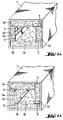
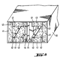
- the sheath shown in Figure 1a or Figure 1b comprises a metal casing 1, one or more sets of four insulating glass wool panels coated on their inner face (2a) with a protective sheet of glass fleece and flipped over their transverse side apparent (2b) by said sheet, and comprises four metal assembly profiles 3 in Z for holding the insulating panels in the sheath.
- the wings of the profiles used can be of the same length as the edge of the insulating panels (figure 1a) or can be of smaller dimension (figure 1b).
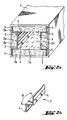
- the sheath shown in Figure 2a corresponds to the sheath shown in Figure 1a in which the "classic" Z-shaped assembly profiles have been replaced by particular Z-shaped profiles whose wings are folded at their free end so as to form a bulge 4; these particular profiles are supported on the casing of the sheath at two points (the end of the bulge and the core of the profile) and make it possible to avoid the problems of condensation between the metal wall and the profiles.
- Each profile also has an angle ⁇ between each wing and the core slightly less than 90 ° so as to allow positioning of the profile core parallel to one face of the sheath and the positioning of the panels perpendicularly to each other while lightly pinching the panels.
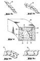
- FIG. 3a represents a ribbon 5 of mineral felt 6 coated with a protective sheet 7 glued and rebound, the ribbon of mineral felt being obtained according to known methods and the rebound being carried out by means of deflector-shaping rollers after application a protective sheet on the underside of the ribbon, this sheet being wider than the face in question.
- the rim is made on the side faces 8 in the direction of travel of the ribbon and on the parts 9 of the upper face adjacent to these side faces.
- Panels 10, 11, 12, 13, 14, 15 are then cut along the dotted lines indicated in FIG. 3a to internally coat the envelope with a sheath of rectangular section in order to obtain a sheath according to the invention. This sheath is produced (FIG.
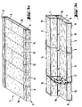
- FIG. 4 represents a sheath according to the invention having a curvature, this sheath comprising a casing 20, insulating panels coated with a protective sheet on their internal face and flanged 21, and assembly profiles 22 in Z which can possibly be have folded edges.
- the assembly profiles used are bent in one or more places in order to follow the curvature of the sheath. In order to bend these sections, it suffices to cut the two wings of the sections along a chosen generatrix (dashed line in FIG. 5a and in FIG. 6a) and to bend the core of the section along this generatrix (FIGS. 5a and 5b, 6a and 6b).
- the insulating panels are also cut or bent to follow the curves of the sheath.
- FIG. 7a schematically shows a top view of the contour of a sheath according to the invention having changes in section.
- the internal coating of this sheath is carried out (FIG. 7b) by returning, by the widest side of the sheath, the lower insulating panel coated with a protective sheet on its internal face and flipped 30 (sheath envelope not shown ), by placing, on the longitudinal edges of this panel, assembly profiles (31, 32) in Z, one of the profiles 31 being folded in several places (after cutting the wings of the profile according to generatrices according to the principle illustrated in FIGS.
- the side panel 33 may be in one piece and have folds along V-shaped notches previously made in the panel or it may be three panels whose edges are cut so as to come into contact with each other , these edges being optionally joined by means of assembly profiles with an approximately T-shaped section whose angle between the core and each of the wings is adapted to the angle between the assembled panels.
- the sheath shown in FIG. 8 comprises a metal casing 40, insulating panels coated on their internal face with a protective sheet and flanged 41, assembly profiles 42 in Z for mounting the panels and a slide 43 consisting of two insulating panels glued to each other, the slide thus obtained being coated with a protective sheet on its two main faces, at least one of the edges transverse to the direction of flow of the sheath of this slide being enclosed in an assembly of two profiles (44, 45) in Z fixed to one another in one of their wings, for example by welding or gluing.
- the assembly shown in Figure 9 comprises two ducts with rectangular section 50, 52 (one of them being partially shown) assembled end to end.
- Each sheath comprises an envelope 54 with a thickness for example of 1 mm.
- This sheath is internally coated with insulating panels 56 based on glass wool or rock with a thickness for example between 20 and 100 mm.
- the internal face of the panels is optionally coated with a fire-resistant layer 60, for example in the form of a glass cloth, this layer also making it possible to clean the interior of the sheath.
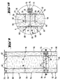
- Each panel 56 comprises two profiles 62 with a thickness for example of 0.7 mm, the core 64 of each profile being in direct contact with only part of a transverse face 65 of the panel, one of the wings 66 penetrating into the insulating material and the other wing 68 covering part of the internal face of the panel (FIG. 10).
- the creation of thermal bridges between the outside and the inside of the sheath is avoided due in particular to the absence of metallic material between the flange of the profile 66 inserted in the panel and the envelope of sheath.
- the panels can for example be fixed by screws (for example self-supporting screws) 70 piercing the envelope of the sheath, part of the insulating material and the wing of the profiles pressed into the insulating material (the thermal bridges at the level of these very punctual elements being relatively unimportant).
- the panels can also be fixed using other screws or devices (such as keys 76 and washers 78 shown in Figure 9) placed for example in the middle of the panel.
- the two sheaths can be connected to each other, as shown more specifically in Figure 10.
- the envelope of each sheath is folded at each of these ends so as to form flanges 72 allowing its assembly with another sheath.
- the edges of two adjacent sheaths are symmetrical in relation to the plane perpendicular to the axis of the sheaths and in the space delimited by these edges is placed a seal 73; a sliding element 74 maintains the joined edges.
- Such flanges can be provided on the end of each face of the sheath.
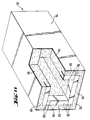
- the sheath shown in Figure 11 is similar to the sheath shown in Figure 9 (the common elements are designated by the same references and this sheath is not provided with screws or flanges for assembly, the assembly of the panels being done for example by gluing or by profiles not shown).
- the coating (the profiles) of the panels of the sheath according to the invention covers, on certain panels, only a part of the transverse edges 80 facing the flow channel of the sheath , this part being essentially the part of the edges directly exposed to the air circulating in the sheath.
- the sheath according to the invention can be used in any ventilation installation and the insulating panels according to the invention can be used in any type of ventilation sheath.
Landscapes
- Engineering & Computer Science (AREA)
- General Engineering & Computer Science (AREA)
- Mechanical Engineering (AREA)
- Chemical & Material Sciences (AREA)
- Combustion & Propulsion (AREA)
- Duct Arrangements (AREA)
- Thermal Insulation (AREA)
- Building Environments (AREA)
- Refrigerator Housings (AREA)
- Application Of Or Painting With Fluid Materials (AREA)
- Thermally Insulated Containers For Foods (AREA)
Abstract
Description
La présente invention concerne une gaine de ventilation comprenant une enveloppe intérieurement revêtue d'au moins un panneau isolant et concerne le panneau en question.The present invention relates to a ventilation duct comprising an envelope internally coated with at least one insulating panel and relates to the panel in question.
Les panneaux isolants habituellement utilisés pour tapisser l'intérieur des gaines de ventilation se présentent généralement sous forme d'un feutre ou matelas de laine minérale (laine de verre ou laine de roche) éventuellement revêtu d'une feuille de matière minérale (par exemple un tissu ou voile de verre ou une feuille d'aluminium) sur sa face « interne » (face destinée à se trouver du côté du passage de l'air dans la gaine) et/ou sur la face opposée à celle-ci. Cette feuille permet par exemple d'éviter l'érosion du feutre de laine minérale et/ou lui confère certaines propriétés thermiques, mécaniques et/ou acoustiques.The insulating panels usually used to line the inside of ventilation ducts are generally in the form of a felt or mattress of mineral wool (glass wool or rock wool) possibly coated with a sheet of mineral material (for example a fabric or glass veil or aluminum foil) on its "internal" face (face intended to be on the side of the passage of air in the sheath) and / or on the face opposite to this. This sheet makes it possible for example to prevent the erosion of the mineral wool felt and / or gives it certain thermal, mechanical and / or acoustic properties.
Dans des gaines de ventilation connues, le ou les panneaux isolants sont montés par collage ou clouage à l'intérieur de la gaine, ces montages étant parfois longs et peu pratiques (notamment le montage par collage). Les panneaux isolants peuvent également être assemblés par l'intermédiaire de profilés permettant entre autres de maintenir ces panneaux dans une position stable au sein de la gaine. De tels assemblages de panneaux et de profilés sont ainsi décrits dans le brevet DE 1 679 519. Les panneaux sont montés côte à côte dans la gaine de façon à assurer une bonne isolation et délimitent le canal d'écoulement de la gaine. Les gaines connues présentent cependant souvent des problèmes d'usure et/ou d'isolation (problèmes d'étanchéité, de condensation - notamment lorsque ces gaines sont utilisées dans des installations de climatisation - création de ponts thermiques etc...) aux endroits de contact des panneaux entre eux, notamment à la jonction des panneaux consécutifs d'une même face de la gaine.In known ventilation ducts, the insulating panel or panels are mounted by gluing or nailing inside the sheath, these assemblies being sometimes long and impractical (in particular assembly by gluing). The insulating panels can also be assembled by means of profiles making it possible inter alia to maintain these panels in a stable position within the sheath. Such assemblies of panels and profiles are thus described in patent DE 1 679 519. The panels are mounted side by side in the sheath so as to ensure good insulation and delimit the channel. sheath flow. The known ducts, however, often have wear and / or insulation problems (sealing, condensation problems - especially when these ducts are used in air conditioning installations - creation of thermal bridges, etc.) at the locations of contact of the panels with each other, in particular at the junction of consecutive panels on the same face of the sheath.
La présente invention remédie aux inconvénients précédemment mentionnés. Elle propose une gaine de ventilation améliorée ne présentant pas de problèmes d'érosion ou d'isolation et étant préférentiellement de montage aisé. La présente invention propose également un panneau isolant amélioré utilisable pour réaliser la gaine selon l'invention.The present invention overcomes the aforementioned drawbacks. It offers an improved ventilation duct which does not present erosion or insulation problems and which is preferably easy to assemble. The present invention also provides an improved insulating panel which can be used to produce the sheath according to the invention.
La gaine de ventilation selon l'invention comprend une enveloppe intérieurement revêtue d'au moins un panneau isolant, ce panneau présentant au moins un revêtement sur au moins une partie d'au moins une de ses arêtes transversales placées du côté du canal d'écoulement de la gaine, ce revêtement s'étendant sur au moins une partie de chacune des faces de part et d'autre de l'arête et étant intégré au panneau.The ventilation duct according to the invention comprises an envelope internally coated with at least one insulating panel, this panel having at least one coating on at least part of at least one of its transverse edges placed on the side of the flow channel of the sheath, this covering extending over at least part of each of the faces on either side of the edge and being integrated into the panel.
Le panneau isolant selon l'invention destiné au revêtement interne d'une gaine de ventilation présente un revêtement sur au moins une partie d'au moins une de ses arêtes, ce revêtement s'étendant sur au moins une partie de chacune des faces de part et d'autre de l'arête et étant intégré au panneau.The insulating panel according to the invention intended for the internal coating of a ventilation duct has a coating on at least a part of at least one of its edges, this coating extending over at least a part of each of the share faces. on either side of the ridge and being integrated into the panel.
Par « gaine de ventilation », on entend une gaine ou canalisation pour le transport de l'air, cette gaine pouvant faire partie par exemple d'une installation de climatisation, d'une installation de chauffage ou d'une installation de ventilation proprement dite.The term "ventilation duct" means a duct or conduit for conveying air, the sheath may form part for example of an air conditioning system, a heating installation or an actual ventilation system .
L'enveloppe de la gaine est généralement métallique ou en béton maçonné et présente, dans la mesure du possible, une section « simple » (de préférence rectangulaire ou carrée, éventuellement cylindrique). Elle peut également se présenter sous forme d'un coude ou comprendre une ou des parties coudées et peut présenter des décrochements, des angles, des changements de section, etc... Cette enveloppe peut également présenter des portions ou sections ouvertes mettant une partie plus ou moins importante du ou des panneaux directement en contact avec l'environnement extérieur de la gaine et peut même se limiter simplement à une armature à la jonction des panneaux isolants. Notamment (cas par exemple des gaines destinées à être montées dans des faux plafonds), l'enveloppe peut simplement consister en un ou plusieurs profilés en T, cintrés ou non, se trouvant à la jonction des panneaux, l'âme de ces profilés étant placée entre les panneaux et les ailes recouvrant les bords des faces des panneaux tournées vers l'extérieur de la gaine.The envelope of the sheath is generally metallic or in masonry concrete and has, as far as possible, a "simple" section (preferably rectangular or square, possibly cylindrical). It can also be in the form of an elbow or include one or more bent parts and can have recesses, angles, changes in section, etc. This envelope can also have open portions or sections putting a more or less important of the panel (s) directly in contact with the external environment of the sheath and can even simply be limited to a reinforcement at the junction of the insulating panels. In particular (case for example ducts intended to be mounted in false ceilings), the envelope may simply consist of one or more T-profiles, curved or not, located at the junction of the panels, the core of these profiles being placed between the panels and the wings covering the edges of the faces of the panels facing outwards from the sheath.
Les panneaux isolants définis dans la présente invention sont ou comprennent de préférence des feutres ou matelas de laine minérale, notamment de laine de verre ou laine de roche. Il peut cependant également s'agir de mousses isolantes ou autres produits similaires plutôt rigides et présentant de bonnes propriétés d'isolation. Les panneaux peuvent présenter plusieurs couches (ou matelas) de matière isolante, éventuellement séparées par des couches ou feuilles de matière différente ou similaire. Ces panneaux sont munis d'au moins un revêtement se présentant préférentiellement sous la forme d'une feuille souple ou d'un élément rigide (tel qu'un profilé comme explicité ultérieurement) en au moins une partie d'au moins une de leurs arêtes, ce revêtement couvrant au moins une partie de chacune des faces situées de part et d'autre de l'arête (l'arête étant commune à deux faces du panneau), l'arête étant destinée à être une arête « transversale » en position montée du panneau dans la gaine. Par « transversal(e) » on entend « transversal(e) à la direction d'écoulement de la gaine ». L'arête en question est également destinée à être placée du côté (sur le pourtour) du canal d'écoulement de la gaine. Le revêtement du panneau selon l'invention couvre ainsi un bord au moins de la face interne du panneau et vient recouvrir (reborder) le bord au moins du côté (ou face) « transversal » (c'est-à-dire présentant quatre arêtes transversales dont l'une se trouve sur le pourtour du canal d'écoulement de la gaine) adjacent au bord de la face interne revêtue. Par « face interne », on entend, comme indiqué précédemment, la face tournée ou destinée à être tournée vers le canal d'écoulement de la gaine, c'est-à-dire du côté du passage de l'air dans la gaine, c'est-à-dire généralement vers le centre de la gaine. Le revêtement couvre avantageusement au moins la partie de l'arête destinée à être exposée à l'air en circulation dans la gaine et couvre généralement la totalité de l'arête.The insulating panels defined in the present invention are or preferably comprise felts or mattresses of mineral wool, in particular glass wool or rock wool. However, it can also be insulating foams or other similar products which are rather rigid and have good insulation properties. The panels may have several layers (or mattresses) of insulating material, possibly separated by layers or sheets of different or similar material. These panels are provided with at least one coating preferably in the form of a flexible sheet or of a rigid element (such as a profile as explained later) in at least part of at least one of their edges. , this covering covering at least part of each of the faces situated on either side of the edge (the edge being common to two faces of the panel), the edge being intended to be a “transverse” edge in position mounting of the panel in the sheath. By "transverse" is meant "transverse to the direction of flow of the sheath". The edge in question is also intended to be placed on the side (around the periphery) of the duct flow channel. The coating of the panel according to the invention thus covers at least one edge of the internal face of the panel and covers (edge) the edge at least on the "transverse" side (or face) (that is to say having four edges transverse, one of which is on the periphery of the duct flow duct) adjacent to the edge of the coated internal face. By "internal face" is meant, as indicated above, the face turned or intended to be turned towards the flow channel of the sheath, that is to say on the side of the passage of air in the sheath, that is to say generally towards the center of the sheath. The coating advantageously covers at least the part of the edge intended to be exposed to the air circulating in the sheath and generally covers the entire edge.
D'autre part, le revêtement est intégré (ou « monté à demeure ») au panneau ; il fait partie du panneau et est lié à la matière isolante présente dans le panneau de façon à obtenir, notamment, une structure cohérente, manipulable, favorisant le moins possible l'apparition de problèmes d'isolation (condensation, etc...). Cette intégration se fait de préférence par « ancrage » (le revêtement, notamment lorsqu'il est sous forme d'un élément rigide, pénètre par exemple en l'une de ses extrémités dans la matière isolante du panneau) ou collage d'au moins une partie du revêtement (notamment lorsque le revêtement se présente sous forme d'une feuille souple).On the other hand, the coating is integrated (or "permanently mounted") to the sign ; it is part of the panel and is linked to the insulating material present in the panel so as to obtain, in particular, a coherent, manipulable structure, promoting as little as possible the appearance of insulation problems (condensation, etc.). This integration is preferably done by "anchoring" (the covering, in particular when it is in the form of a rigid element, penetrates for example at one of its ends into the insulating material of the panel) or bonding of at least part of the covering (especially when the covering is in the form of a flexible sheet).
De préférence, le panneau présente un revêtement tel que défini selon l'invention en chacune (ou partie de chacune) de ses arêtes destinées à être placées du côté du canal d'écoulement de la gaine et transversalement à la direction d'écoulement de la gaine.Preferably, the panel has a coating as defined according to the invention in each (or part of each) of its edges intended to be placed on the side of the flow channel of the sheath and transverse to the direction of flow of the sheath.
La gaine et les panneaux selon l'invention présentent de multiples avantages. Ils présentent notamment une meilleure résistance à l'érosion et l'isolation au sein de la gaine est améliorée, la protection des bords des panneaux se trouvant du côté du passage de l'air étant particulièrement renforcée du fait de la présence du revêtement défini selon l'invention. La préhension des panneaux et le confort de pose sont également améliorés.The sheath and the panels according to the invention have multiple advantages. They have in particular better resistance to erosion and the insulation within the sheath is improved, the protection of the edges of the panels located on the side of the air passage being particularly reinforced due to the presence of the coating defined according to the invention. The gripping of the panels and the installation comfort are also improved.
En règle générale, les panneaux isolants définis dans la présente invention sont déjà recouverts, sur leur face interne, d'une feuille de protection, cette feuille pouvant protéger les panneaux de l'usure et pouvant, le cas échéant, présenter d'autres propriétés : étanchéité, réduction du frottement de l'air, résistance mécanique, renforcement du caractère isolant acoustique ou thermique, effet de membrane, etc... Cette feuille est généralement une feuille de matière minérale. Elle peut par exemple être un voile ou un tissu de verre, imprégné ou non d'un liant organique ou inorganique, mais peut être également une feuille d'aluminium, etc...In general, the insulating panels defined in the present invention are already covered, on their internal face, with a protective sheet, this sheet being able to protect the panels from wear and being able, where appropriate, to have other properties. : sealing, reduction of air friction, mechanical resistance, reinforcement of the acoustic or thermal insulating character, membrane effect, etc. This sheet is generally a sheet of mineral material. It can for example be a veil or a glass fabric, impregnated or not with an organic or inorganic binder, but can also be an aluminum foil, etc.
Les panneaux peuvent être également revêtus d'une feuille de matière minérale en leur face opposée à la face interne (face externe), cette feuille étant identique ou différente à la feuille de protection précédemment citée et présentant les mêmes propriétés ou des propriétés différentes. Les feuilles revêtant les panneaux selon l'invention sont généralement collées auxdits panneaux, par exemple par l'intermédiaire du liant imprégnant les feuilles.The panels can also be coated with a sheet of mineral material on their face opposite to the internal face (external face), this sheet being identical or different to the previously mentioned protective sheet and having the same or different properties. The sheets coating the panels according to the invention are generally bonded to said panels, for example by means of the binder impregnating the sheets.
Selon un mode de réalisation de la présente invention, les panneaux définis selon l'invention sont revêtus sur leur face interne d'une telle feuille de protection au moins et sont « rebordés » (c'est-à-dire que la feuille recouvrant la face interne vient recouvrir également au moins une partie d'une face adjacente) par la feuille en au moins une partie d'un des côtés devant être placé transversalement à la direction d'écoulement de la gaine, ce côté étant adjacent à la face interne. Dans ce cas, le revêtement défini selon l'invention est constitué par la feuille de protection venant ainsi reborder au moins un coin du panneau exposé au passage de l'air. De préférence, les panneaux rebordés utilisés ou utilisables dans la gaine selon l'invention sont des panneaux revêtus par une feuille de protection sur leur face interne et en au moins un de leur côté destiné à être positionné transversalement à la direction d'écoulement de la gaine ainsi que sur la partie de la face externe adjacente audit côté. De préférence également, les panneaux isolants selon l'invention sont rebordés par la feuille de protection en leurs deux côtés transversaux à la direction d'écoulement de la gaine.According to one embodiment of the present invention, the panels defined according to the invention are coated on their internal face with at least one such protective sheet and are "rimmed" (that is to say that the sheet covering the internal face also covers at least part of an adjacent face) with the sheet in at least part of one of the sides to be placed transversely to the direction of flow of the sheath, this side being adjacent to the internal face . In this case, the coating defined according to the invention is constituted by the protective sheet which thus overlaps at least one corner of the panel exposed to the passage of air. Preferably, the rimmed panels used or usable in the sheath according to the invention are panels coated with a protective sheet on their internal face and on at least one of their side intended to be positioned transversely to the direction of flow of the sheath as well as on the part of the external face adjacent to said side. Also preferably, the insulating panels according to the invention are rimmed by the protective sheet in their two sides transverse to the direction of flow of the sheath.
Dans ce mode de réalisation, il est possible d'augmenter les vitesses de circulation de l'air au sein des gaines selon l'invention sans risques d'arrachement de fibres des panneaux ou même d'arrachement de la feuille de protection revêtant la face interne des panneaux. Ces panneaux sont obtenus, par exemple, en fabriquant selon des méthodes habituelles et connues un ruban continu de feutre de laine minérale que l'on collecte sur un convoyeur, puis en appliquant sur la face inférieure de ce ruban une feuille de protection imprégnée d'un liant assurant le collage de la feuille au feutre, puis en rebordant les faces latérales et une partie de la face supérieure du ruban par l'intermédiaire de guides ou de molettes déflecteurs-conformateurs. Le ruban est ultérieurement découpé sous forme de panneaux isolants en conservant au moins un des côtés rebordés du feutre dans chaque panneau.In this embodiment, it is possible to increase the air circulation speeds within the sheaths according to the invention without risk of tearing fibers from the panels or even tearing the protective sheet coating the face internal panels. These panels are obtained, for example, by manufacturing according to usual and known methods a continuous ribbon of mineral wool felt which is collected on a conveyor, then by applying to the underside of this ribbon a protective sheet impregnated with a binder ensuring the bonding of the sheet to the felt, then by rebounding the lateral faces and part of the upper face of the ribbon by means of guides or deflector-shaping rollers. The tape is subsequently cut in the form of insulating panels, retaining at least one of the curved sides of the felt in each panel.
Selon un autre mode de réalisation de l'invention, le panneau utilisé, muni ou non d'une feuille de protection sur sa face interne (et/ou sur sa face externe) rebordant ou non ce panneau, présente au moins un revêtement sous forme d'un profilé à section en U dont l'âme recouvre une partie d'un côté du panneau destiné à être monté transversalement à la direction d'écoulement de la gaine, dont l'une des ailes pénètre (rentre en force) dans le matériau isolant du panneau et dont l'autre aile couvre une partie de la face interne du panneau.According to another embodiment of the invention, the panel used, whether or not provided with a protective sheet on its internal face (and / or on its external face) which may or may not border this panel, has at least one coating in the form of a U-shaped section whose core covers part of one side of the panel intended to be mounted transversely to the direction of flow of the sheath, one of the wings of which penetrates (comes into force) in the insulating material of the panel and the other wing of which covers part of the internal face of the panel.
De préférence, le panneau présente au moins un revêtement sous forme d'un profilé à section en U sur une partie de chacun des côtés transversaux du panneau (le panneau est alors muni de deux profilés par exemple), chaque profilé étant placé comme indiqué dans le paragraphe précédent.Preferably, the panel has at least one covering in the form of a U-section profile on a part of each of the transverse sides of the panel (the panel is then provided with two profiles for example), each profile being placed as indicated in the previous paragraph.
Les panneaux selon l'invention peuvent être collés, cloués ou « clipsés » à l'intérieur de la gaine. De préférence cependant, la gaine comprend au moins un profilé d'assemblage des panneaux et les panneaux sont montés de façon simple, rapide et pratique, par l'intermédiaire du ou des profilés d'assemblage. Le ou les profilés d'assemblage sont généralement métalliques, ou éventuellement en matière plastique, et présentent, de préférence, une forme de Z, c'est-à-dire présentent une âme et deux ailes, chaque aile étant à une extrémité différente de l'âme et les deux ailes étant de part et d'autre du plan passant par l'âme. Ce ou ces profilés servant au maintien du ou des panneaux sont placés longitudinalement dans la direction d'écoulement de la gaine. Les profilés d'assemblage en Z sont particulièrement appropriés lorsque les gaines selon l'invention se présentent sous forme de quadrilatères et sont intérieurement revêtues par un ou des ensembles de quatre panneaux. Le montage des panneaux dans la gaine se fait alors, par exemple, de la façon suivante : un premier panneau est posé sur la face inférieure de la gaine et deux profilés en Z sont placés chacun sur un bord du panneau dans le sens d'écoulement de la gaine ; les panneaux latéraux sont ensuite placés chacun sur un des profilés et deux autres profilés en Z viennent chacun coiffer l'un des panneaux latéraux. Le dernier panneau vient se glisser dans les parties supérieures des deux derniers profilés en Z. Le ou les ensembles consécutifs de quatre panneaux sont ainsi maintenus par un ou des ensembles consécutifs de quatre profilés en Z.The panels according to the invention can be glued, nailed or "clipped" inside the sheath. Preferably, however, the sheath comprises at least one profile for assembling the panels and the panels are mounted in a simple, rapid and practical manner, by means of the assembly profile or profiles. The assembly profile (s) are generally metallic, or possibly made of plastic, and preferably have a Z shape, that is to say have a core and two wings, each wing being at a different end from the soul and the two wings being on either side of the plane passing through the soul. This or these sections used to hold the panel or panels are placed longitudinally in the direction of flow of the sheath. The Z-shaped joining profiles are particularly suitable when the sheaths according to the invention are in the form of quadrilaterals and are internally coated with one or more sets of four panels. The panels are then mounted in the sheath, for example, as follows: a first panel is placed on the underside of the sheath and two Z-profiles are each placed on one edge of the panel in the flow direction sheath; the side panels are then each placed on one of the profiles and two other Z-profiles each cover one of the side panels. The last panel slides into the upper parts of the last two Z-sections. The consecutive set or sets of four panels are thus held by one or more consecutive sets of four Z-sections.
Les profilés d'assemblage en Z s'adaptent à tous les types de gaine mentionnés précédemment ; il est notamment possible de cintrer ces profilés pour qu'ils puissent épouser les courbes des gaines en coupant suivant une génératrice les deux ailes des profilés dans le sens de la largeur et en pliant l'âme du profilé le long de cette même génératrice. On peut ainsi faire plusieurs pliures à des angles plus ou moins faibles ou importants en suivant la courbure de la gaine. De la même façon, les panneaux isolants selon l'invention peuvent être légèrement cintrés ou pliés suivant une entaille (par exemple une entaille en V) pratiquée dans les panneaux, de façon à suivre les courbes ou angles de la gaine.The Z-shaped assembly profiles adapt to all the types of sheath mentioned above; it is in particular possible to bend these profiles so that they can follow the curves of the sheaths by cutting along a generatrix the two wings of the profiles in the width direction and by bending the web of the profile along this same generatrix. It is thus possible to make several folds at more or less small or large angles by following the curvature of the sheath. In the same way, the insulating panels according to the invention can be slightly bent or folded along a notch (for example a V-notch) formed in the panels, so as to follow the curves or angles of the sheath.
Selon un mode de réalisation de l'invention particulièrement préféré, les profilés d'assemblage en Z utilisés dans la gaine selon l'invention présentent au moins une aile et de préférence des ailes dont l'extrémité libre est rabattue vers « l'extérieur », c'est-à-dire du côté de l'aile non tourné vers l'âme. Contrairement aux profilés en Z classiques, ces profilés en Z aux extrémités repliées ne présentent pas de bords coupants risquant notamment d'accrocher les panneaux isolants mais présentent des bords arrondis plus sécurisants et permettant un meilleur montage. De plus, de tels profilés en Z aux bords repliés ne posent pas les problèmes de condensation qui peuvent éventuellement se poser avec les profilés en Z traditionnels ; en effet grâce au renflement formé par chaque extrémité repliée, les profilés en Z prennent normalement appui uniquement en deux points de l'enveloppe de la gaine, ce qui empêche l'emprisonnement d'air à cet endroit et la condensation de l'air entre des éléments de la gaine généralement métalliques. L'angle entre chaque aile et l'âme du profilé est choisi de façon à permettre le positionnement voulu des panneaux isolants dans la gaine et est généralement proche de 90°. De préférence, particulièrement dans le cas des profilés d'assemblage en Z présentant au moins un bord replié, l'angle entre chaque aile et l'âme du profilé est légèrement inférieur à 90°. Par exemple, dans le cas des profilés en Z présentant au moins un bord replié, cet angle aigu est choisi, comme illustré ultérieurement à la figure 2, de façon à ce que l'extrémité du renflement et l'extrémité de l'âme du profilé soient alignés suivant une perpendiculaire à l'âme, cette construction permettant d'assembler deux panneaux perpendiculairement l'un à l'autre. Le choix d'un angle légèrement inférieur à 90° entre l'âme et chaque aile du profilé permet également d'obtenir, le cas échéant, un léger pincement des panneaux et donc un meilleur maintien de ces panneaux.According to a particularly preferred embodiment of the invention, the Z-shaped assembly profiles used in the sheath according to the invention have at least one wing and preferably wings whose free end is folded down towards the "outside" , that is to say on the side of the wing not turned towards the core. Unlike conventional Z-shaped profiles, these Z-shaped profiles with folded ends do not have sharp edges, risking in particular the insulating panels, but have rounded edges which are more secure and allow better mounting. In addition, such Z profiles with folded edges do not pose the condensation problems which may possibly arise with traditional Z profiles; in fact, thanks to the bulge formed by each folded end, the Z-profiles normally take support only at two points of the sheath envelope, which prevents the trapping of air at this location and the condensation of air between generally metallic sheath elements. The angle between each wing and the core of the profile is chosen so as to allow the desired positioning of the insulating panels in the sheath and is generally close to 90 °. Preferably, particularly in the case of Z-shaped assembly profiles having at least one folded edge, the angle between each wing and the web of the profile is slightly less than 90 °. For example, in the case of Z-shaped profiles having at least one folded edge, this acute angle is chosen, as illustrated later in FIG. 2, so that the end of the bulge and the end of the core of the are aligned along a perpendicular to the core, this construction making it possible to assemble two panels perpendicular to one another. The choice of an angle slightly less than 90 ° between the core and each wing of the profile also makes it possible to obtain, if necessary, a slight pinching of the panels and therefore better support of these panels.
Dans le cas de gaines particulièrement longues revêtues intérieurement de plusieurs ensembles de panneaux consécutifs, la jonction de deux panneaux consécutifs utilisés pour tapisser une même face de la gaine peut être améliorée par l'intermédiaire d'autres profilés d'assemblage, notamment lorsque l'un des panneaux n'est revêtu que sur un des côtés et est en contact avec un autre panneau sur son côté non revêtu. Le profilé utilisé peut être un profilé en Z auquel cas l'âme du profilé se trouve entre les deux panneaux et une des ailes du profilé recouvre une partie de la face interne du profilé présentant le côté non revêtu. Ce mode de réalisation présente l'avantage de ne nécessiter qu'un type de profilé d'assemblage dans la gaine. On peut cependant utiliser plus simplement et avantageusement un profilé en T dont l'âme se trouve entre les deux panneaux et les ailes recouvrent les bords des faces internes des deux panneaux. Ce mode est particulièrement avantageux lorsque les deux panneaux sont revêtus en un seul côté et que le contact entre les deux panneaux se fait sur leur côté non revêtu. Le profilé en T utilisé peut éventuellement être légèrement cintré suivant les courbures de la gaine.In the case of particularly long sheaths coated internally with several sets of consecutive panels, the junction of two consecutive panels used to line the same face of the sheath can be improved by means of other assembly profiles, in particular when the one of panels are coated on only one side and are in contact with another panel on their uncoated side. The profile used can be a Z-shaped profile in which case the core of the profile is located between the two panels and one of the wings of the profile covers part of the internal face of the profile having the uncoated side. This embodiment has the advantage of requiring only one type of assembly profile in the sheath. However, it is possible to use more simply and advantageously a T-profile whose core is between the two panels and the wings cover the edges of the internal faces of the two panels. This mode is particularly advantageous when the two panels are coated on one side and the contact between the two panels is made on their uncoated side. The T-profile used can possibly be slightly curved according to the curvatures of the sheath.
Dans le cas de gaines présentant au moins une coulisse (ensemble comprenant au moins deux panneaux d'isolation utilisé pour partager le canal d'écoulement de la gaine en plusieurs canaux), la protection de la ou des coulisses peut encore être améliorée au moyen de profilés d'assemblage en Z, notamment de deux profilés en Z dont l'âme se trouve dans un même plan sur le chant des panneaux, les deux profilés étant assemblés chacun le long d'une de leurs ailes et les deux ailes restantes enserrant les deux panneaux isolants comme illustré ultérieurement. L'utilisation de ces profilés dans ce cas évite également le passage de l'air entre les deux panneaux constituant les coulisses. On peut également utiliser d'autres protections (tel qu'un élément à base de matière isolante en forme de demi-cylindre plein que l'on protège à l'aide de profilés, par exemple à l'aide de profilés en Z) et/ou d'autres profilés (profilé en U), ce mode de réalisation présentant simplement le désavantage de nécessiter d'autres types d'éléments ou de profilés.In the case of ducts having at least one slide (assembly comprising at least two insulation panels used to divide the flow channel of the duct into several channels), the protection of the slide (s) can be further improved by means of Z-shaped assembly profiles, in particular two Z-shaped profiles whose core is in the same plane on the edge of the panels, the two profiles each being assembled along one of their wings and the two remaining wings enclosing the two insulating panels as shown later. The use of these profiles in this case also prevents the passage of air between the two panels constituting the slides. It is also possible to use other protections (such as an element based on insulating material in the form of a solid half-cylinder which is protected using profiles, for example using Z profiles) and / or other profiles (U-shaped), this embodiment simply has the disadvantage of requiring other types of elements or profiles.
D'autres avantages et caractéristiques de l'invention apparaîtront à la lumière des dessins suivants illustrant l'invention, sans toutefois la limiter, dans lesquels :
- les figures 1a et 1b représentent des vues schématiques en perspective d'une extrémité de gaine selon l'invention, cette gaine étant munie d'un revêtement interne comprenant des panneaux isolants et des profilés d'assemblage en Z, les deux figures illustrant deux arrangements différents possibles des profilés et des panneaux isolants à l'intérieur de la gaine,
- la figure 2a représente une vue schématique en perspective d'une extrémité d'une gaine préférée selon l'invention munie d'un revêtement interne comprenant des panneaux isolants et des profilés d'assemblage en Z présentant des bords repliés ; la figure 2b représente une vue schématique du type de profilé utilisé dans cette gaine,
- la figure 3a représente une vue schématique en perspective d'un ruban continu de feutre de laine minérale revêtu sur une face d'une feuille de protection et rebordé, dans lequel on découpe des panneaux isolants, la figure 3b représentant une partie du revêtement interne d'une gaine selon l'invention réalisée à partir desdits panneaux isolants découpés,
- la figure 4 représente une vue schématique en perspective d'une gaine coudée selon l'invention, les figures 5a et 5b, 6a et 6b représentant les profilés d'assemblage utilisés dans cette gaine avant et après découpe de leurs ailes et cintrage,
- la figure 7a représente une vue schématique de dessus d'une gaine selon l'invention, une partie du revêtement interne de cette gaine étant représenté en perspective figure 7b,
- la figure 8 représente une vue schématique en perspective d'une extrémité d'une gaine selon l'invention présentant une coulisse,
- la figure 9 représente une vue de dessus (la partie supérieure de l'enveloppe et les panneaux supérieurs étant ôtés) d'un assemblage de gaines selon l'invention et la figure 10 représente un agrandissement de la partie A de la figure 9,
- la figure 11 représente une vue schématique en perspective d'une extrémité d'une gaine similaire à celles de la figure 9.
- Figures 1a and 1b show schematic perspective views of a sheath end according to the invention, this sheath being provided with an internal coating comprising insulating panels and Z-shaped assembly profiles, the two figures illustrating two arrangements different possible profiles and insulating panels inside the sheath,
- FIG. 2a represents a schematic perspective view of one end of a preferred sheath according to the invention provided with an internal coating comprising insulating panels and Z-shaped assembly profiles having folded edges; FIG. 2b represents a schematic view of the type of profile used in this sheath,
- FIG. 3a represents a schematic perspective view of a continuous ribbon of mineral wool felt coated on one side with a protective sheet and wrapped, in which insulating panels are cut, FIG. 3b representing a part of the internal covering d a sheath according to the invention produced from said cut insulating panels,
- FIG. 4 represents a schematic perspective view of a bent sheath according to the invention, FIGS. 5a and 5b, 6a and 6b showing the assembly profiles used in this sheath before and after cutting their wings and bending,
- FIG. 7a represents a schematic top view of a sheath according to the invention, part of the internal coating of this sheath being shown in perspective in FIG. 7b,
- FIG. 8 represents a schematic perspective view of one end of a sheath according to the invention having a slide,
- FIG. 9 represents a top view (the upper part of the envelope and the upper panels being removed) of an assembly of sheaths according to the invention and FIG. 10 represents an enlargement of part A of FIG. 9,
- FIG. 11 represents a schematic perspective view of one end of a sheath similar to those of FIG. 9.
La gaine représentée figure 1a ou figure 1b comprend une enveloppe métallique 1, un ou plusieurs ensembles de quatre panneaux isolants en laine de verre revêtus sur leur face interne (2a) d'une feuille de protection en voile de verre et rebordés sur leur côté transversal apparent (2b) par ladite feuille, et comprend quatre profilés métalliques d'assemblage 3 en Z permettant de maintenir les panneaux isolants dans la gaine. Les ailes des profilés utilisés peuvent être de la même longueur que le chant des panneaux isolants (figure 1a) ou peuvent être de dimension plus faible (figure 1b).The sheath shown in Figure 1a or Figure 1b comprises a metal casing 1, one or more sets of four insulating glass wool panels coated on their inner face (2a) with a protective sheet of glass fleece and flipped over their transverse side apparent (2b) by said sheet, and comprises four
La gaine représentée en figure 2a correspond à la gaine représentée en figure 1a dans laquelle les profilés d'assemblage en Z « classiques » ont été remplacés par des profilés en Z particuliers dont les ailes sont repliées en leur extrémité libre de façon à former un renflement 4 ; ces profilés particuliers prennent appui sur l'enveloppe de la gaine en deux points (l'extrémité du renflement et l'âme du profilé) et permettent d'éviter les problèmes de condensation entre la paroi métallique et les profilés. Chaque profilé présente également un angle α entre chaque aile et l'âme légèrement inférieur à 90° de façon à permettre un positionnement de l'âme du profilé parallèlement à une face de la gaine et le positionnement des panneaux perpendiculairement les uns aux autres tout en effectuant un léger pincement des panneaux.The sheath shown in Figure 2a corresponds to the sheath shown in Figure 1a in which the "classic" Z-shaped assembly profiles have been replaced by particular Z-shaped profiles whose wings are folded at their free end so as to form a
La figure 3a représente un ruban 5 de feutre minéral 6 revêtu d'une feuille de protection 7 collée et rebordé, le ruban de feutre minéral étant obtenu selon des méthodes connues et le rebordement étant effectué par l'intermédiaire de molettes déflecteurs-conformateurs après application d'une feuille de protection sur la face inférieure du ruban, cette feuille étant plus large que la face en question. Le rebordement se fait sur les faces latérales 8 dans la direction de défilement du ruban et sur les parties 9 de la face supérieure adjacentes à ces faces latérales. Des panneaux 10, 11, 12, 13, 14, 15 sont ensuite découpés suivant les pointillés indiqués en figure 3a pour revêtir intérieurement l'enveloppe d'une gaine de section rectangulaire afin d'obtenir une gaine selon l'invention. Cette gaine est réalisée (figure 3b) en posant le nombre nécessaire de panneaux (10, 11, 12) pour tapisser la face inférieure de la gaine, sur l'enveloppe (non représentée) de la gaine, le ou les côtés rebordés des panneaux étant disposés transversalement au passage de l'air et les faces principales revêtues de la feuille de protection étant tournées vers l'intérieur de la gaine, puis en posant des profilés d'assemblage 16 en Z (présentant éventuellement des bords repliés) sur les bords longitudinaux de ces panneaux (profilés sur le devant de la figure non représentés), puis en posant les panneaux isolants latéraux (13, 14, 15) sur les profilés (panneaux de devant non représentés) avant d'intercaler à nouveau des profilés et de poser les panneaux supérieurs (non représentés). Des panneaux (12, 15) de longueur plus petite que la largeur standard du ruban de feutre étant utilisés dans ce mode de réalisation, ces panneaux ne présentant par conséquent qu'un côté rebordé, sont protégés en leur côté non rebordé par un profilé d'assemblage 17 à section en T (entièrement représenté) intercalé entre ces panneaux et les panneaux consécutifs.FIG. 3a represents a
La figure 4 représente une gaine selon l'invention présentant une courbure, cette gaine comprenant une enveloppe 20, des panneaux isolants revêtus d'une feuille de protection sur leur face interne et rebordés 21, et des profilés d'assemblage 22 en Z pouvant éventuellement présenter des bords repliés. Les profilés d'assemblage utilisés sont cintrés en un ou plusieurs endroits afin de suivre la courbure de la gaine. Afin de cintrer ces profilés il suffit de couper les deux ailes des profilés suivant une génératrice choisie(trait mixte de la figure 5a et de la figure 6a) et de cintrer l'âme du profilé suivant cette génératrice (figures 5a et 5b, 6a et 6b). Les panneaux isolants sont également découpés ou cintrés pour suivre les courbes de la gaine.FIG. 4 represents a sheath according to the invention having a curvature, this sheath comprising a
La figure 7a représente schématiquement en vue de dessus le contour d'une gaine selon l'invention présentant des changements de section. Le revêtement interne de cette gaine est effectué (figure 7b) en rentrant, par le côté le plus large de la gaine, le panneau isolant inférieur revêtu d'une feuille de protection sur sa face interne et rebordé 30 (enveloppe de la gaine non représentée), en posant, sur les bords longitudinaux de ce panneau, des profilés d'assemblage (31, 32) en Z, l'un des profilés 31 étant plié en plusieurs endroits (après coupure des ailes du profilé suivant des génératrices selon le principe illustré figures 5a, 5b, 6a et 6b), ces profilés présentant éventuellement des bords repliés, puis en posant les panneaux isolants latéraux (33, 34) sur les profilés avant d'intercaler à nouveau des profilés d'assemblage et de glisser le panneau supérieur (non représentés) sur ces profilés. Le panneau latéral 33 peut être en une seule pièce et présenter des pliures le long d'entailles en V préalablement pratiquées dans le panneau ou il peut s'agir de trois panneaux dont les bords sont découpés de façon à venir en contact les uns des autres, ces bords étant éventuellement joints par l'intermédiaire de profilés d'assemblage à section approximativement en T dont l'angle entre l'âme et chacune des ailes est adapté à l'angle entre les panneaux assemblés.Figure 7a schematically shows a top view of the contour of a sheath according to the invention having changes in section. The internal coating of this sheath is carried out (FIG. 7b) by returning, by the widest side of the sheath, the lower insulating panel coated with a protective sheet on its internal face and flipped 30 (sheath envelope not shown ), by placing, on the longitudinal edges of this panel, assembly profiles (31, 32) in Z, one of the
La gaine représentée en figure 8 comprend une enveloppe métallique 40, des panneaux isolants revêtus sur leur face interne d'une feuille de protection et rebordés 41, des profilés d'assemblage 42 en Z pour le montage des panneaux et une coulisse 43 constituée de deux panneaux isolants collés l'un à l'autre, la coulisse ainsi obtenue étant revêtue d'une feuille de protection sur ses deux faces principales, au moins un des bords transversaux à la direction d'écoulement de la gaine de cette coulisse étant enserré dans un assemblage de deux profilés (44, 45) en Z fixés l'un à l'autre en l'une de leurs ailes, par exemple par soudure ou collage.The sheath shown in FIG. 8 comprises a
L'assemblage représenté en figure 9 comprend deux gaines à section rectangulaire 50, 52 (l'une d'elles étant partiellement représentée) assemblées bout à bout. Chaque gaine comprend une enveloppe 54 d'une épaisseur par exemple de 1 mm. Cette gaine est intérieurement revêtue de panneaux isolants 56 à base de laine de verre ou de roche d'une épaisseur par exemple comprise entre 20 et 100 mm. La face interne des panneaux est éventuellement revêtue d'une couche anti-feu 60, sous forme par exemple d'un tissu de verre, cette couche permettant également le nettoyage de l'intérieur de la gaine. Chaque panneau 56 comprend deux profilés 62 d'une épaisseur par exemple de 0,7 mm, l'âme 64 de chaque profilé étant en contact direct avec une partie seulement d'une face transversale 65 du panneau, une des ailes 66 pénétrant dans le matériau isolant et l'autre aile 68 recouvrant une partie de la face interne du panneau (figure 10). Dans ce mode de réalisation, la création de ponts thermiques entre l'extérieur et l'intérieur de la gaine est évitée du fait notamment de l'absence de matériau métallique entre l'aile du profilé 66 insérée dans le panneau et l'enveloppe de la gaine.The assembly shown in Figure 9 comprises two ducts with
Les panneaux peuvent par exemple être fixés par des vis (par exemple des vis auto-porteuses) 70 transperçant l'enveloppe de la gaine, une partie de la matière isolante et l'aile des profilés enfoncée dans la matière isolante (les ponts thermiques au niveau de ces éléments très ponctuels étant relativement peu importants). Les panneaux peuvent également être fixés à l'aide d'autres vis ou dispositifs (tels que les clavettes 76 et rondelles 78 représentées en figure 9) placés par exemple au milieu du panneau.The panels can for example be fixed by screws (for example self-supporting screws) 70 piercing the envelope of the sheath, part of the insulating material and the wing of the profiles pressed into the insulating material (the thermal bridges at the level of these very punctual elements being relatively unimportant). The panels can also be fixed using other screws or devices (such as
Les deux gaines peuvent être reliées l'une à l'autre, comme représenté plus précisément en figure 10. L'enveloppe de chaque gaine est repliée en chacune de ces extrémités de façon à former des rebords 72 permettant son assemblage avec une autre gaine. Les rebords de deux gaines adjacentes sont de forme symétrique par rapport au plan perpendiculaire à l'axe des gaines et dans l'espace délimité par ces rebords est placée une garniture d'étanchéité 73 ; un élément coulissant 74 maintient les rebords joints. De tels rebords peuvent être prévus sur l'extrémité de chaque face de la gaine.The two sheaths can be connected to each other, as shown more specifically in Figure 10. The envelope of each sheath is folded at each of these ends so as to form
La gaine représentée en figure 11 est similaire à la gaine représentée en figure 9 (les éléments communs étant désignés par les mêmes références et cette gaine n'étant pas munie de vis ou de rebords pour l'assemblage, l'assemblage des panneaux se faisant par exemple par collage ou par des profilés non représentés). Dans ce mode de réalisation, on observe que le revêtement (les profilés) des panneaux de la gaine selon l'invention, ne couvre, sur certains panneaux, qu'une partie des arêtes transversales 80 tournées vers le canal d'écoulement de la gaine, cette partie étant essentiellement la partie des arêtes directement exposée à l'air en circulation dans la gaine.The sheath shown in Figure 11 is similar to the sheath shown in Figure 9 (the common elements are designated by the same references and this sheath is not provided with screws or flanges for assembly, the assembly of the panels being done for example by gluing or by profiles not shown). In this embodiment, it is observed that the coating (the profiles) of the panels of the sheath according to the invention, covers, on certain panels, only a part of the
La gaine selon l'invention peut être utilisée dans toute installation de ventilation et les panneaux isolants selon l'invention peuvent être utilisés dans tout type de gaine de ventilation.The sheath according to the invention can be used in any ventilation installation and the insulating panels according to the invention can be used in any type of ventilation sheath.
Claims (10)
Applications Claiming Priority (4)
| Application Number | Priority Date | Filing Date | Title |
|---|---|---|---|
| FR9512986 | 1995-11-03 | ||
| FR9512986A FR2740804B1 (en) | 1995-11-03 | 1995-11-03 | VENTILATION SHEATH AND INSULATING PANEL USED FOR ITS INTERNAL COATING |
| SE9504476 | 1995-12-14 | ||
| SE9504476A SE505567C2 (en) | 1995-12-14 | 1995-12-14 | Ventilation duct with inner insulation panels |
Publications (2)
| Publication Number | Publication Date |
|---|---|
| EP0772009A1 true EP0772009A1 (en) | 1997-05-07 |
| EP0772009B1 EP0772009B1 (en) | 2002-05-22 |
Family
ID=26232305
Family Applications (1)
| Application Number | Title | Priority Date | Filing Date |
|---|---|---|---|
| EP96402293A Expired - Lifetime EP0772009B1 (en) | 1995-11-03 | 1996-10-29 | Insulating panels used as a lining of ventilation duct |
Country Status (7)
| Country | Link |
|---|---|
| US (2) | US5975146A (en) |
| EP (1) | EP0772009B1 (en) |
| AT (1) | ATE217954T1 (en) |
| DE (1) | DE69621307T2 (en) |
| DK (1) | DK0772009T3 (en) |
| ES (1) | ES2175050T3 (en) |
| PT (1) | PT772009E (en) |
Cited By (2)
| Publication number | Priority date | Publication date | Assignee | Title |
|---|---|---|---|---|
| GB2471777A (en) * | 2009-07-08 | 2011-01-12 | Ursa Iborica Aislantes Sa | Thermal-Acoustic Insulation Panel |
| WO2022053700A1 (en) * | 2020-09-14 | 2022-03-17 | Saint-Gobain Isover Iberica, S.L. | Panel for air-conditioning ducts |
Families Citing this family (37)
| Publication number | Priority date | Publication date | Assignee | Title |
|---|---|---|---|---|
| CA2142190C (en) * | 1995-02-14 | 1998-01-27 | Marc Lessard | Waste air exfiltration duct |
| DK0772009T3 (en) * | 1995-11-03 | 2002-09-16 | Saint Gobain Isover | Ventilation duct and insulating panel for covering this |
| JP3352065B2 (en) * | 1999-12-13 | 2002-12-03 | 双葉電子工業株式会社 | Fluorescent display tube and driving method thereof |
| US6497255B1 (en) * | 2001-07-13 | 2002-12-24 | Carrier Corporation | Floor panel for air handling unit |
| US6497256B1 (en) * | 2001-07-13 | 2002-12-24 | Carrier Corporation | Thermal barrier for air handling unit (AHU) cabinet |
| DE60326733D1 (en) * | 2002-06-24 | 2009-04-30 | Saint Gobain Isover | INSULATING PLATE FOR FEED CHANNEL |
| US7140396B2 (en) * | 2002-11-27 | 2006-11-28 | Johns Manville | Air duct containing an organic liner material |
| US7597534B2 (en) | 2003-03-20 | 2009-10-06 | Huntair, Inc. | Fan array fan section in air-handling systems |
| US7137775B2 (en) | 2003-03-20 | 2006-11-21 | Huntair Inc. | Fan array fan section in air-handling systems |
| US11255332B2 (en) | 2003-03-20 | 2022-02-22 | Nortek Air Solutions, Llc | Modular fan housing with multiple modular units having sound attenuation for a fan array for an air-handling system |
| US7044171B2 (en) * | 2003-05-28 | 2006-05-16 | James W. Betley | Exterior ductwork system |
| BRPI0415028A (en) * | 2003-10-06 | 2006-12-12 | Saint Gobain Isover | ventilation and / or air conditioning duct and its internal / external coating |
| ATE315207T1 (en) * | 2003-10-06 | 2006-02-15 | Saint Gobain Isover G & H Ag | CLIMATE OR VENTILATION DUCT |
| US20050092384A1 (en) * | 2003-10-29 | 2005-05-05 | Superior Air Ducts | Semi-flexible air duct |
| ES2243119B1 (en) * | 2003-11-03 | 2007-02-16 | Saint-Gobain Cristaleria, S.A. | BEADED BY PANEL COATING FOR CONSTRUCTION OF AIR CONDITIONING PIPES. |
| US8511978B2 (en) * | 2006-05-02 | 2013-08-20 | United Technologies Corporation | Airfoil array with an endwall depression and components of the array |
| EP2053320A1 (en) * | 2007-10-24 | 2009-04-29 | P3 S.r.l. | Joint system for joining ends of panels made of insulated material |
| UA103188C2 (en) * | 2008-03-04 | 2013-09-25 | Роквул Інтернешнл А/С | Fire protection of structural element |
| AU2010214924B2 (en) | 2009-02-18 | 2015-10-22 | Walsh Intellectual Property Ltd. | A tubular duct member |
| CN102303366B (en) * | 2011-07-01 | 2013-12-18 | 董光明 | Industrialized production line for exhaust passages |
| US20130295303A1 (en) * | 2012-05-02 | 2013-11-07 | Owens Corning Intellectual Capital, Llc | Duct liner |
| US9528261B2 (en) | 2013-01-09 | 2016-12-27 | Vita Nonwovens, Llc | Synthetic fiber insulation with facing |
| GB2514533B (en) * | 2013-03-08 | 2020-01-29 | Ronald Dalgarno Michael | Thermally insulated duct members |
| CN104125752A (en) * | 2013-04-29 | 2014-10-29 | 鸿富锦精密工业(深圳)有限公司 | Wind shield |
| US9371941B1 (en) * | 2013-11-06 | 2016-06-21 | Ptm Manufacturing, Llc | Exterior ductwork system |
| CN106471317B (en) * | 2014-05-07 | 2021-03-12 | 迈克尔·罗纳德·达尔加诺 | Conveying pipe section |
| US11402121B2 (en) * | 2015-03-25 | 2022-08-02 | Sterling Custom Sheet Metal, Inc. | Insulated register box with boot rail adaptor |
| CN108603683A (en) * | 2016-01-12 | 2018-09-28 | 亿康先达国际集团股份有限公司 | For the pass element of ventilating system, pass element system and building envelope equipped with the pass element system |
| ITUA20164322A1 (en) * | 2016-06-13 | 2017-12-13 | Sts Isolamenti S R L | SILENT VENTILATION DUCT |
| JP6752654B2 (en) * | 2016-08-17 | 2020-09-09 | 株式会社荏原製作所 | A sound deadening member and a sound deadening structure using this sound deadening member |
| US10976070B1 (en) | 2017-03-31 | 2021-04-13 | Albers Mechanical Contractors, Inc. | Foam core duct system protected by metal sleeves with integral flanges |
| DE102017210562A1 (en) * | 2017-06-22 | 2018-12-27 | Mahle International Gmbh | Sound damping arrangement for an air conditioning system of a motor vehicle |
| US10365005B2 (en) * | 2017-07-12 | 2019-07-30 | Fernando Surraco | Stainless steel foil laminated plastic HVAC duct and method of making same |
| WO2019212528A1 (en) | 2018-05-01 | 2019-11-07 | Volpe Miles | Telescopic vent |
| US10731539B1 (en) * | 2018-05-01 | 2020-08-04 | Touchstone Resarch Labratory, Ltd | Composite exhaust flue |
| DE102021207777A1 (en) | 2021-07-21 | 2023-01-26 | Volkswagen Aktiengesellschaft | Air duct arrangement for a motor vehicle, motor vehicle |
| US11927137B2 (en) * | 2022-03-21 | 2024-03-12 | Ge Infrastructure Technology Llc | System and method for insulating components in an exhaust gas flow from a gas turbine |
Citations (4)
| Publication number | Priority date | Publication date | Assignee | Title |
|---|---|---|---|---|
| DE1679519A1 (en) | 1967-12-19 | 1971-04-08 | Gruenzweig & Hartmann | Sound-absorbing, heat-insulating air duct |
| FR2468076A1 (en) * | 1979-10-18 | 1981-04-30 | Air Ind | Air diffusion ducting for ventilation system - is made of sound-attenuating material covered with sheet metal formed into duct comprising facing U=shaped channels |
| WO1982003248A1 (en) * | 1981-03-20 | 1982-09-30 | Abc Corp Peabody | Sound attenuator |
| EP0074486A1 (en) * | 1981-09-01 | 1983-03-23 | Gretsch-Unitas GmbH Baubeschläge | Slide plate ventilation with a fan driven by a motor |
Family Cites Families (16)
| Publication number | Priority date | Publication date | Assignee | Title |
|---|---|---|---|---|
| US1063672A (en) * | 1911-07-19 | 1913-06-03 | William C Flannery | Process of constructing sewers, aqueducts, &c. |
| US3317074A (en) * | 1963-06-17 | 1967-05-02 | Douglas Aircraft Co Inc | Cryogenic containers |
| US3835606A (en) * | 1972-05-22 | 1974-09-17 | M Liberman | Combination ceiling tile and air duct structure |
| DE2808387B2 (en) * | 1978-02-27 | 1979-12-20 | Gutehoffnungshuette Sterkrade Ag, 4200 Oberhausen | Steel-concrete composite lining for manholes |
| US4280536A (en) * | 1978-08-23 | 1981-07-28 | Erich Gnant | Connecting device for insulated duct work |
| US4462618A (en) * | 1981-03-16 | 1984-07-31 | Wallace-Murray Corporation | Prefabricated double-walled metal chimney |
| DK164303C (en) * | 1990-05-14 | 1992-10-19 | Vik Consult | INSULATION FOR A PIPE OR CHANNEL WITH A RELATIVE LOW SURFACE TEMPERATURE AND PROCEDURE FOR PREPARING THE INSULATION |
| GB2262192A (en) * | 1991-11-28 | 1993-06-09 | Zortech Int | Insulated duct for electric cables |
| US5487412A (en) * | 1993-05-26 | 1996-01-30 | Schuller International, Inc. | Glass fiber airduct with coated interior surface containing a biocide |
| US5379806A (en) * | 1993-05-26 | 1995-01-10 | Schuller International, Inc. | Fiber glass air duct with coated interior surface containing an organic biocide |
| US5783268A (en) * | 1993-08-11 | 1998-07-21 | Knauf Fiber Glass Gmbh | High air velocity duct board having minimal turbulence |
| US5654060A (en) * | 1995-06-16 | 1997-08-05 | The Boeing Company | High temperature insulation system |
| ES1032658Y (en) * | 1995-09-22 | 1996-10-16 | Cristaleria Espan | PROFILE OF TERMINATION OF JOINTS, FOR PRODUCTS OF GLASS WOOL TYPE "CLIMAVER PLUS". |
| DK0772009T3 (en) * | 1995-11-03 | 2002-09-16 | Saint Gobain Isover | Ventilation duct and insulating panel for covering this |
| US5918644A (en) * | 1996-05-23 | 1999-07-06 | Haack; C. William | Air duct and method of making same |
| US6000437A (en) * | 1998-01-16 | 1999-12-14 | Certain Teed Corporation | Coated liner for curved ducts |
-
1996
- 1996-10-29 DK DK96402293T patent/DK0772009T3/en active
- 1996-10-29 AT AT96402293T patent/ATE217954T1/en active
- 1996-10-29 EP EP96402293A patent/EP0772009B1/en not_active Expired - Lifetime
- 1996-10-29 ES ES96402293T patent/ES2175050T3/en not_active Expired - Lifetime
- 1996-10-29 PT PT96402293T patent/PT772009E/en unknown
- 1996-10-29 DE DE69621307T patent/DE69621307T2/en not_active Expired - Lifetime
- 1996-11-04 US US08/743,158 patent/US5975146A/en not_active Expired - Lifetime
-
1999
- 1999-08-16 US US09/374,108 patent/US6161593A/en not_active Expired - Lifetime
Patent Citations (4)
| Publication number | Priority date | Publication date | Assignee | Title |
|---|---|---|---|---|
| DE1679519A1 (en) | 1967-12-19 | 1971-04-08 | Gruenzweig & Hartmann | Sound-absorbing, heat-insulating air duct |
| FR2468076A1 (en) * | 1979-10-18 | 1981-04-30 | Air Ind | Air diffusion ducting for ventilation system - is made of sound-attenuating material covered with sheet metal formed into duct comprising facing U=shaped channels |
| WO1982003248A1 (en) * | 1981-03-20 | 1982-09-30 | Abc Corp Peabody | Sound attenuator |
| EP0074486A1 (en) * | 1981-09-01 | 1983-03-23 | Gretsch-Unitas GmbH Baubeschläge | Slide plate ventilation with a fan driven by a motor |
Cited By (5)
| Publication number | Priority date | Publication date | Assignee | Title |
|---|---|---|---|---|
| GB2471777A (en) * | 2009-07-08 | 2011-01-12 | Ursa Iborica Aislantes Sa | Thermal-Acoustic Insulation Panel |
| GB2471777B (en) * | 2009-07-08 | 2015-04-29 | Ursa Ib Rica Aislantes Sa | Mineral wool thermal-acoustic insulation panel |
| WO2022053700A1 (en) * | 2020-09-14 | 2022-03-17 | Saint-Gobain Isover Iberica, S.L. | Panel for air-conditioning ducts |
| FR3114045A1 (en) * | 2020-09-14 | 2022-03-18 | Saint-Gobain Isover Iberica, S.L. | PANEL FOR AIR CONDITIONING DUCT |
| US12420531B2 (en) | 2020-09-14 | 2025-09-23 | Saint-Gobain Isover | Panel for air-conditioning ducts |
Also Published As
| Publication number | Publication date |
|---|---|
| DE69621307D1 (en) | 2002-06-27 |
| US5975146A (en) | 1999-11-02 |
| EP0772009B1 (en) | 2002-05-22 |
| PT772009E (en) | 2002-10-31 |
| US6161593A (en) | 2000-12-19 |
| ATE217954T1 (en) | 2002-06-15 |
| DE69621307T2 (en) | 2002-12-12 |
| DK0772009T3 (en) | 2002-09-16 |
| ES2175050T3 (en) | 2002-11-16 |
Similar Documents
| Publication | Publication Date | Title |
|---|---|---|
| EP0772009B1 (en) | Insulating panels used as a lining of ventilation duct | |
| FR2472640A1 (en) | THERMAL AND ACOUSTIC INSULATION STRUCTURE FOR CLADDING OR OTHER NON-CARRIER WALL | |
| EP0553012A1 (en) | Watertight roof covering device | |
| EP1565625B1 (en) | Flexible thermal insulation material comprising at least one open-work layer | |
| FR2740804A1 (en) | Ventilation duct with inner insulation panels | |
| EP0433164B1 (en) | Insulating and fireproofed partitioning panel | |
| EP1130190B1 (en) | Acoustic insulating layer for floating floors | |
| FR2469519A1 (en) | Wall cladding for articulating boards - comprises parallel edge abutting boards connected tendons across rear faces enabling it to roll up for transit | |
| EP1426239B1 (en) | Seal and sound insulation sheet for a vehicle body élément, such as a car door | |
| WO1998042930A1 (en) | Insulating board | |
| FR3011862A1 (en) | BUILDING MODULE | |
| EP4536917A1 (en) | Interior wall lining for acoustic insulation | |
| EP0557170B1 (en) | Insulating and impervious roof for buildings | |
| FR2847651A1 (en) | Thermal insulation panel for buildings has covering film layer projecting beyond at least one edge of insulating material to overlap adjacent panel | |
| EP1321594A1 (en) | Insulation composite | |
| FR2572503A1 (en) | Radiator mfr. system for underfloor central heating | |
| FR2875520A1 (en) | Modular panel for surface covering e.g. ceiling, has frame including profile that has longitudinal parts with U-shaped and L-shaped transversal sections, where side of one section is contiguous to upper part of side of another section | |
| EP0494029B1 (en) | Metallic panel for covering or filling-up supporting structures f.i. facades or roofs | |
| FR2977265A1 (en) | Thermal insulation panel, useful for frontage of building, comprises first and second layers connected by an interface zone, where a first face and a second face are defined by the first and second layers respectively | |
| EP2582891A1 (en) | Assembly comprising at least one construction panel with at least one spacer inserted in the interior thereof, and method for mounting the assembly | |
| FR2854940A1 (en) | Multilayer insulator for walls of buildings, comprises sheets of polyester fibres coated on one side with reflecting aluminum foil and laid in two layers with displaced but joints | |
| EP1541777A1 (en) | Covering tape for masking slab or panel joints | |
| FR2672914A1 (en) | Bridging device | |
| FR2982523A1 (en) | Method for manufacturing flexible multi-layer thermal insulation material utilized in building site, involves arranging side rebate part on side of multi-layer part, where rabbet part and side rabbet part allow assembly of flexible material | |
| FR2523180A3 (en) | Inflammable sound deadening panel - comprises hollow structure consisting of two metallic sheets filled with inflammable material |
Legal Events
| Date | Code | Title | Description |
|---|---|---|---|
| PUAI | Public reference made under article 153(3) epc to a published international application that has entered the european phase |
Free format text: ORIGINAL CODE: 0009012 |
|
| AK | Designated contracting states |
Kind code of ref document: A1 Designated state(s): AT BE CH DE DK ES FI FR GB IT LI NL PT SE |
|
| 17P | Request for examination filed |
Effective date: 19970530 |
|
| 17Q | First examination report despatched |
Effective date: 20000119 |
|
| GRAG | Despatch of communication of intention to grant |
Free format text: ORIGINAL CODE: EPIDOS AGRA |
|
| GRAG | Despatch of communication of intention to grant |
Free format text: ORIGINAL CODE: EPIDOS AGRA |
|
| GRAH | Despatch of communication of intention to grant a patent |
Free format text: ORIGINAL CODE: EPIDOS IGRA |
|
| RAP1 | Party data changed (applicant data changed or rights of an application transferred) |
Owner name: SAINT-GOBAIN ISOVER |
|
| GRAH | Despatch of communication of intention to grant a patent |
Free format text: ORIGINAL CODE: EPIDOS IGRA |
|
| GRAA | (expected) grant |
Free format text: ORIGINAL CODE: 0009210 |
|
| REF | Corresponds to: |
Ref document number: 217954 Country of ref document: AT Date of ref document: 20020615 Kind code of ref document: T |
|
| REG | Reference to a national code |
Ref country code: GB Ref legal event code: FG4D Free format text: NOT ENGLISH |
|
| REG | Reference to a national code |
Ref country code: CH Ref legal event code: EP |
|
| REF | Corresponds to: |
Ref document number: 69621307 Country of ref document: DE Date of ref document: 20020627 |
|
| REG | Reference to a national code |
Ref country code: CH Ref legal event code: NV Representative=s name: KIRKER & CIE SA |
|
| GBT | Gb: translation of ep patent filed (gb section 77(6)(a)/1977) |
Effective date: 20020816 |
|
| REG | Reference to a national code |
Ref country code: DK Ref legal event code: T3 |
|
| REG | Reference to a national code |
Ref country code: PT Ref legal event code: SC4A Free format text: AVAILABILITY OF NATIONAL TRANSLATION Effective date: 20020726 |
|
| REG | Reference to a national code |
Ref country code: ES Ref legal event code: FG2A Ref document number: 2175050 Country of ref document: ES Kind code of ref document: T3 |
|
| PLBE | No opposition filed within time limit |
Free format text: ORIGINAL CODE: 0009261 |
|
| STAA | Information on the status of an ep patent application or granted ep patent |
Free format text: STATUS: NO OPPOSITION FILED WITHIN TIME LIMIT |
|
| 26N | No opposition filed |
Effective date: 20030225 |
|
| PGFP | Annual fee paid to national office [announced via postgrant information from national office to epo] |
Ref country code: DK Payment date: 20121010 Year of fee payment: 17 |
|
| PGFP | Annual fee paid to national office [announced via postgrant information from national office to epo] |
Ref country code: BE Payment date: 20121025 Year of fee payment: 17 Ref country code: DE Payment date: 20121211 Year of fee payment: 17 Ref country code: CH Payment date: 20121012 Year of fee payment: 17 Ref country code: FI Payment date: 20121010 Year of fee payment: 17 |
|
| PGFP | Annual fee paid to national office [announced via postgrant information from national office to epo] |
Ref country code: PT Payment date: 20120430 Year of fee payment: 17 Ref country code: SE Payment date: 20121011 Year of fee payment: 17 Ref country code: GB Payment date: 20121024 Year of fee payment: 17 |
|
| PGFP | Annual fee paid to national office [announced via postgrant information from national office to epo] |
Ref country code: AT Payment date: 20120927 Year of fee payment: 17 Ref country code: NL Payment date: 20121010 Year of fee payment: 17 |
|
| PGFP | Annual fee paid to national office [announced via postgrant information from national office to epo] |
Ref country code: ES Payment date: 20130911 Year of fee payment: 18 |
|
| PGFP | Annual fee paid to national office [announced via postgrant information from national office to epo] |
Ref country code: IT Payment date: 20130906 Year of fee payment: 18 |
|
| BERE | Be: lapsed |
Owner name: *SAINT-GOBAIN ISOVER Effective date: 20131031 |
|
| REG | Reference to a national code |
Ref country code: PT Ref legal event code: MM4A Free format text: LAPSE DUE TO NON-PAYMENT OF FEES Effective date: 20140429 |
|
| REG | Reference to a national code |
Ref country code: NL Ref legal event code: V1 Effective date: 20140501 |
|
| REG | Reference to a national code |
Ref country code: DK Ref legal event code: EBP Effective date: 20131031 |
|
| REG | Reference to a national code |
Ref country code: CH Ref legal event code: PL |
|
| REG | Reference to a national code |
Ref country code: SE Ref legal event code: EUG |
|
| REG | Reference to a national code |
Ref country code: AT Ref legal event code: MM01 Ref document number: 217954 Country of ref document: AT Kind code of ref document: T Effective date: 20131029 |
|
| GBPC | Gb: european patent ceased through non-payment of renewal fee |
Effective date: 20131029 |
|
| REG | Reference to a national code |
Ref country code: DE Ref legal event code: R119 Ref document number: 69621307 Country of ref document: DE Effective date: 20140501 |
|
| PG25 | Lapsed in a contracting state [announced via postgrant information from national office to epo] |
Ref country code: LI Free format text: LAPSE BECAUSE OF NON-PAYMENT OF DUE FEES Effective date: 20131031 Ref country code: GB Free format text: LAPSE BECAUSE OF NON-PAYMENT OF DUE FEES Effective date: 20131029 Ref country code: CH Free format text: LAPSE BECAUSE OF NON-PAYMENT OF DUE FEES Effective date: 20131031 |
|
| PG25 | Lapsed in a contracting state [announced via postgrant information from national office to epo] |
Ref country code: FI Free format text: LAPSE BECAUSE OF NON-PAYMENT OF DUE FEES Effective date: 20131029 Ref country code: AT Free format text: LAPSE BECAUSE OF NON-PAYMENT OF DUE FEES Effective date: 20131029 Ref country code: DE Free format text: LAPSE BECAUSE OF NON-PAYMENT OF DUE FEES Effective date: 20140501 Ref country code: PT Free format text: LAPSE BECAUSE OF NON-PAYMENT OF DUE FEES Effective date: 20140429 Ref country code: SE Free format text: LAPSE BECAUSE OF NON-PAYMENT OF DUE FEES Effective date: 20131030 Ref country code: NL Free format text: LAPSE BECAUSE OF NON-PAYMENT OF DUE FEES Effective date: 20140501 |
|
| PG25 | Lapsed in a contracting state [announced via postgrant information from national office to epo] |
Ref country code: BE Free format text: LAPSE BECAUSE OF NON-PAYMENT OF DUE FEES Effective date: 20131031 |
|
| PG25 | Lapsed in a contracting state [announced via postgrant information from national office to epo] |
Ref country code: DK Free format text: LAPSE BECAUSE OF NON-PAYMENT OF DUE FEES Effective date: 20131031 |
|
| PG25 | Lapsed in a contracting state [announced via postgrant information from national office to epo] |
Ref country code: IT Free format text: LAPSE BECAUSE OF NON-PAYMENT OF DUE FEES Effective date: 20141029 |
|
| REG | Reference to a national code |
Ref country code: FR Ref legal event code: PLFP Year of fee payment: 20 |
|
| REG | Reference to a national code |
Ref country code: ES Ref legal event code: FD2A Effective date: 20151127 |
|
| PG25 | Lapsed in a contracting state [announced via postgrant information from national office to epo] |
Ref country code: ES Free format text: LAPSE BECAUSE OF NON-PAYMENT OF DUE FEES Effective date: 20141030 |
|
| PGFP | Annual fee paid to national office [announced via postgrant information from national office to epo] |
Ref country code: FR Payment date: 20151022 Year of fee payment: 20 |