EP0772009A1 - Lüftungskanal und Isolierplatten für seine Auskleidung - Google Patents
Lüftungskanal und Isolierplatten für seine Auskleidung Download PDFInfo
- Publication number
- EP0772009A1 EP0772009A1 EP96402293A EP96402293A EP0772009A1 EP 0772009 A1 EP0772009 A1 EP 0772009A1 EP 96402293 A EP96402293 A EP 96402293A EP 96402293 A EP96402293 A EP 96402293A EP 0772009 A1 EP0772009 A1 EP 0772009A1
- Authority
- EP
- European Patent Office
- Prior art keywords
- panel
- panels
- sheath
- insulating
- profiles
- Prior art date
- Legal status (The legal status is an assumption and is not a legal conclusion. Google has not performed a legal analysis and makes no representation as to the accuracy of the status listed.)
- Granted
Links
- 238000009423 ventilation Methods 0.000 title claims abstract description 16
- 239000011490 mineral wool Substances 0.000 claims abstract description 9
- 239000011248 coating agent Substances 0.000 claims description 25
- 238000000576 coating method Methods 0.000 claims description 25
- 230000001681 protective effect Effects 0.000 claims description 19
- 239000011810 insulating material Substances 0.000 claims description 10
- 238000009413 insulation Methods 0.000 abstract description 10
- 229910052500 inorganic mineral Inorganic materials 0.000 abstract description 6
- 239000011707 mineral Substances 0.000 abstract description 6
- 239000011521 glass Substances 0.000 abstract description 5
- 239000011491 glass wool Substances 0.000 abstract description 5
- 239000000463 material Substances 0.000 abstract description 5
- 239000004744 fabric Substances 0.000 abstract description 4
- 238000009833 condensation Methods 0.000 description 5
- 230000005494 condensation Effects 0.000 description 5
- 238000004026 adhesive bonding Methods 0.000 description 4
- 238000009434 installation Methods 0.000 description 4
- 229910052751 metal Inorganic materials 0.000 description 4
- 239000002184 metal Substances 0.000 description 4
- 230000004224 protection Effects 0.000 description 4
- 239000011230 binding agent Substances 0.000 description 3
- 238000005520 cutting process Methods 0.000 description 3
- 230000003628 erosive effect Effects 0.000 description 3
- 238000004378 air conditioning Methods 0.000 description 2
- 229910052782 aluminium Inorganic materials 0.000 description 2
- XAGFODPZIPBFFR-UHFFFAOYSA-N aluminium Chemical compound [Al] XAGFODPZIPBFFR-UHFFFAOYSA-N 0.000 description 2
- 230000000712 assembly Effects 0.000 description 2
- 238000000429 assembly Methods 0.000 description 2
- 238000005452 bending Methods 0.000 description 2
- 239000011888 foil Substances 0.000 description 2
- 238000000034 method Methods 0.000 description 2
- 230000002787 reinforcement Effects 0.000 description 2
- 238000007789 sealing Methods 0.000 description 2
- 238000007493 shaping process Methods 0.000 description 2
- 230000001154 acute effect Effects 0.000 description 1
- 244000245420 ail Species 0.000 description 1
- 238000004873 anchoring Methods 0.000 description 1
- YFXPPSKYMBTNAV-UHFFFAOYSA-N bensultap Chemical compound C=1C=CC=CC=1S(=O)(=O)SCC(N(C)C)CSS(=O)(=O)C1=CC=CC=C1 YFXPPSKYMBTNAV-UHFFFAOYSA-N 0.000 description 1
- 210000004027 cell Anatomy 0.000 description 1
- 230000001427 coherent effect Effects 0.000 description 1
- 238000010276 construction Methods 0.000 description 1
- 230000000694 effects Effects 0.000 description 1
- 239000000835 fiber Substances 0.000 description 1
- 230000009970 fire resistant effect Effects 0.000 description 1
- 239000006260 foam Substances 0.000 description 1
- 238000010438 heat treatment Methods 0.000 description 1
- 230000010354 integration Effects 0.000 description 1
- 238000005304 joining Methods 0.000 description 1
- 238000004519 manufacturing process Methods 0.000 description 1
- 239000012528 membrane Substances 0.000 description 1
- 239000007769 metal material Substances 0.000 description 1
- 230000000149 penetrating effect Effects 0.000 description 1
- 239000004033 plastic Substances 0.000 description 1
- 230000001737 promoting effect Effects 0.000 description 1
- 239000011435 rock Substances 0.000 description 1
- 239000007787 solid Substances 0.000 description 1
- 238000003466 welding Methods 0.000 description 1
Images

Classifications
-
- F—MECHANICAL ENGINEERING; LIGHTING; HEATING; WEAPONS; BLASTING
- F24—HEATING; RANGES; VENTILATING
- F24F—AIR-CONDITIONING; AIR-HUMIDIFICATION; VENTILATION; USE OF AIR CURRENTS FOR SCREENING
- F24F13/00—Details common to, or for air-conditioning, air-humidification, ventilation or use of air currents for screening
- F24F13/02—Ducting arrangements
- F24F13/0263—Insulation for air ducts
-
- F—MECHANICAL ENGINEERING; LIGHTING; HEATING; WEAPONS; BLASTING
- F16—ENGINEERING ELEMENTS AND UNITS; GENERAL MEASURES FOR PRODUCING AND MAINTAINING EFFECTIVE FUNCTIONING OF MACHINES OR INSTALLATIONS; THERMAL INSULATION IN GENERAL
- F16L—PIPES; JOINTS OR FITTINGS FOR PIPES; SUPPORTS FOR PIPES, CABLES OR PROTECTIVE TUBING; MEANS FOR THERMAL INSULATION IN GENERAL
- F16L59/00—Thermal insulation in general
- F16L59/14—Arrangements for the insulation of pipes or pipe systems
- F16L59/147—Arrangements for the insulation of pipes or pipe systems the insulation being located inwardly of the outer surface of the pipe
-
- F—MECHANICAL ENGINEERING; LIGHTING; HEATING; WEAPONS; BLASTING
- F24—HEATING; RANGES; VENTILATING
- F24F—AIR-CONDITIONING; AIR-HUMIDIFICATION; VENTILATION; USE OF AIR CURRENTS FOR SCREENING
- F24F13/00—Details common to, or for air-conditioning, air-humidification, ventilation or use of air currents for screening
- F24F13/02—Ducting arrangements
- F24F13/0209—Ducting arrangements characterised by their connecting means, e.g. flanges
-
- F—MECHANICAL ENGINEERING; LIGHTING; HEATING; WEAPONS; BLASTING
- F24—HEATING; RANGES; VENTILATING
- F24F—AIR-CONDITIONING; AIR-HUMIDIFICATION; VENTILATION; USE OF AIR CURRENTS FOR SCREENING
- F24F13/00—Details common to, or for air-conditioning, air-humidification, ventilation or use of air currents for screening
- F24F13/02—Ducting arrangements
- F24F13/0281—Multilayer duct
-
- F—MECHANICAL ENGINEERING; LIGHTING; HEATING; WEAPONS; BLASTING
- F24—HEATING; RANGES; VENTILATING
- F24F—AIR-CONDITIONING; AIR-HUMIDIFICATION; VENTILATION; USE OF AIR CURRENTS FOR SCREENING
- F24F13/00—Details common to, or for air-conditioning, air-humidification, ventilation or use of air currents for screening
- F24F13/24—Means for preventing or suppressing noise
Definitions
- the present invention relates to a ventilation duct comprising an envelope internally coated with at least one insulating panel and relates to the panel in question.
- the insulating panels usually used to line the inside of ventilation ducts are generally in the form of a felt or mattress of mineral wool (glass wool or rock wool) possibly coated with a sheet of mineral material (for example a fabric or glass veil or aluminum foil) on its "internal" face (face intended to be on the side of the passage of air in the sheath) and / or on the face opposite to this.
- This sheet makes it possible for example to prevent the erosion of the mineral wool felt and / or gives it certain thermal, mechanical and / or acoustic properties.
- the insulating panel or panels are mounted by gluing or nailing inside the sheath, these assemblies being sometimes long and impractical (in particular assembly by gluing).
- the insulating panels can also be assembled by means of profiles making it possible inter alia to maintain these panels in a stable position within the sheath. Such assemblies of panels and profiles are thus described in patent DE 1 679 519. The panels are mounted side by side in the sheath so as to ensure good insulation and delimit the channel. sheath flow.
- the known ducts however, often have wear and / or insulation problems (sealing, condensation problems - especially when these ducts are used in air conditioning installations - creation of thermal bridges, etc.) at the locations of contact of the panels with each other, in particular at the junction of consecutive panels on the same face of the sheath.
- the present invention overcomes the aforementioned drawbacks. It offers an improved ventilation duct which does not present erosion or insulation problems and which is preferably easy to assemble.
- the present invention also provides an improved insulating panel which can be used to produce the sheath according to the invention.
- the ventilation duct according to the invention comprises an envelope internally coated with at least one insulating panel, this panel having at least one coating on at least part of at least one of its transverse edges placed on the side of the flow channel of the sheath, this covering extending over at least part of each of the faces on either side of the edge and being integrated into the panel.
- the insulating panel according to the invention intended for the internal coating of a ventilation duct has a coating on at least a part of at least one of its edges, this coating extending over at least a part of each of the share faces. on either side of the ridge and being integrated into the panel.
- ventilation duct means a duct or conduit for conveying air, the sheath may form part for example of an air conditioning system, a heating installation or an actual ventilation system .
- the envelope of the sheath is generally metallic or in masonry concrete and has, as far as possible, a "simple" section (preferably rectangular or square, possibly cylindrical). It can also be in the form of an elbow or include one or more bent parts and can have recesses, angles, changes in section, etc. This envelope can also have open portions or sections putting a more or less important of the panel (s) directly in contact with the external environment of the sheath and can even simply be limited to a reinforcement at the junction of the insulating panels.
- the envelope may simply consist of one or more T-profiles, curved or not, located at the junction of the panels, the core of these profiles being placed between the panels and the wings covering the edges of the faces of the panels facing outwards from the sheath.
- the insulating panels defined in the present invention are or preferably comprise felts or mattresses of mineral wool, in particular glass wool or rock wool. However, it can also be insulating foams or other similar products which are rather rigid and have good insulation properties.
- the panels may have several layers (or mattresses) of insulating material, possibly separated by layers or sheets of different or similar material. These panels are provided with at least one coating preferably in the form of a flexible sheet or of a rigid element (such as a profile as explained later) in at least part of at least one of their edges. , this covering covering at least part of each of the faces situated on either side of the edge (the edge being common to two faces of the panel), the edge being intended to be a “transverse” edge in position mounting of the panel in the sheath.
- transverse is meant “transverse to the direction of flow of the sheath”.
- the edge in question is also intended to be placed on the side (around the periphery) of the duct flow channel.
- the coating of the panel according to the invention thus covers at least one edge of the internal face of the panel and covers (edge) the edge at least on the "transverse" side (or face) (that is to say having four edges transverse, one of which is on the periphery of the duct flow duct) adjacent to the edge of the coated internal face.
- internal face is meant, as indicated above, the face turned or intended to be turned towards the flow channel of the sheath, that is to say on the side of the passage of air in the sheath, that is to say generally towards the center of the sheath.
- the coating advantageously covers at least the part of the edge intended to be exposed to the air circulating in the sheath and generally covers the entire edge.
- the coating is integrated (or “permanently mounted") to the sign ; it is part of the panel and is linked to the insulating material present in the panel so as to obtain, in particular, a coherent, manipulable structure, promoting as little as possible the appearance of insulation problems (condensation, etc.).
- This integration is preferably done by “anchoring” (the covering, in particular when it is in the form of a rigid element, penetrates for example at one of its ends into the insulating material of the panel) or bonding of at least part of the covering (especially when the covering is in the form of a flexible sheet).
- the panel has a coating as defined according to the invention in each (or part of each) of its edges intended to be placed on the side of the flow channel of the sheath and transverse to the direction of flow of the sheath.
- the sheath and the panels according to the invention have multiple advantages. They have in particular better resistance to erosion and the insulation within the sheath is improved, the protection of the edges of the panels located on the side of the air passage being particularly reinforced due to the presence of the coating defined according to the invention. The gripping of the panels and the installation comfort are also improved.
- the insulating panels defined in the present invention are already covered, on their internal face, with a protective sheet, this sheet being able to protect the panels from wear and being able, where appropriate, to have other properties. : sealing, reduction of air friction, mechanical resistance, reinforcement of the acoustic or thermal insulating character, membrane effect, etc.
- This sheet is generally a sheet of mineral material. It can for example be a veil or a glass fabric, impregnated or not with an organic or inorganic binder, but can also be an aluminum foil, etc.
- the panels can also be coated with a sheet of mineral material on their face opposite to the internal face (external face), this sheet being identical or different to the previously mentioned protective sheet and having the same or different properties.
- the sheets coating the panels according to the invention are generally bonded to said panels, for example by means of the binder impregnating the sheets.
- the panels defined according to the invention are coated on their internal face with at least one such protective sheet and are "rimmed" (that is to say that the sheet covering the internal face also covers at least part of an adjacent face) with the sheet in at least part of one of the sides to be placed transversely to the direction of flow of the sheath, this side being adjacent to the internal face .
- the coating defined according to the invention is constituted by the protective sheet which thus overlaps at least one corner of the panel exposed to the passage of air.
- the rimmed panels used or usable in the sheath according to the invention are panels coated with a protective sheet on their internal face and on at least one of their side intended to be positioned transversely to the direction of flow of the sheath as well as on the part of the external face adjacent to said side.
- the insulating panels according to the invention are rimmed by the protective sheet in their two sides transverse to the direction of flow of the sheath.
- the panel used whether or not provided with a protective sheet on its internal face (and / or on its external face) which may or may not border this panel, has at least one coating in the form of a U-shaped section whose core covers part of one side of the panel intended to be mounted transversely to the direction of flow of the sheath, one of the wings of which penetrates (comes into force) in the insulating material of the panel and the other wing of which covers part of the internal face of the panel.
- the panel has at least one covering in the form of a U-section profile on a part of each of the transverse sides of the panel (the panel is then provided with two profiles for example), each profile being placed as indicated in the previous paragraph.
- the panels according to the invention can be glued, nailed or "clipped" inside the sheath.
- the sheath comprises at least one profile for assembling the panels and the panels are mounted in a simple, rapid and practical manner, by means of the assembly profile or profiles.
- the assembly profile (s) are generally metallic, or possibly made of plastic, and preferably have a Z shape, that is to say have a core and two wings, each wing being at a different end from the soul and the two wings being on either side of the plane passing through the soul. This or these sections used to hold the panel or panels are placed longitudinally in the direction of flow of the sheath.
- the Z-shaped joining profiles are particularly suitable when the sheaths according to the invention are in the form of quadrilaterals and are internally coated with one or more sets of four panels.
- the panels are then mounted in the sheath, for example, as follows: a first panel is placed on the underside of the sheath and two Z-profiles are each placed on one edge of the panel in the flow direction sheath; the side panels are then each placed on one of the profiles and two other Z-profiles each cover one of the side panels. The last panel slides into the upper parts of the last two Z-sections. The consecutive set or sets of four panels are thus held by one or more consecutive sets of four Z-sections.
- the Z-shaped assembly profiles adapt to all the types of sheath mentioned above; it is in particular possible to bend these profiles so that they can follow the curves of the sheaths by cutting along a generatrix the two wings of the profiles in the width direction and by bending the web of the profile along this same generatrix. It is thus possible to make several folds at more or less small or large angles by following the curvature of the sheath.
- the insulating panels according to the invention can be slightly bent or folded along a notch (for example a V-notch) formed in the panels, so as to follow the curves or angles of the sheath.
- the Z-shaped assembly profiles used in the sheath according to the invention have at least one wing and preferably wings whose free end is folded down towards the "outside" , that is to say on the side of the wing not turned towards the core.
- these Z-shaped profiles with folded ends do not have sharp edges, risking in particular the insulating panels, but have rounded edges which are more secure and allow better mounting.
- Z profiles with folded edges do not pose the condensation problems which may possibly arise with traditional Z profiles; in fact, thanks to the bulge formed by each folded end, the Z-profiles normally take support only at two points of the sheath envelope, which prevents the trapping of air at this location and the condensation of air between generally metallic sheath elements.
- the angle between each wing and the core of the profile is chosen so as to allow the desired positioning of the insulating panels in the sheath and is generally close to 90 °.
- the angle between each wing and the web of the profile is slightly less than 90 °.
- this acute angle is chosen, as illustrated later in FIG. 2, so that the end of the bulge and the end of the core of the are aligned along a perpendicular to the core, this construction making it possible to assemble two panels perpendicular to one another.
- the choice of an angle slightly less than 90 ° between the core and each wing of the profile also makes it possible to obtain, if necessary, a slight pinching of the panels and therefore better support of these panels.
- the junction of two consecutive panels used to line the same face of the sheath can be improved by means of other assembly profiles, in particular when the one of panels are coated on only one side and are in contact with another panel on their uncoated side.
- the profile used can be a Z-shaped profile in which case the core of the profile is located between the two panels and one of the wings of the profile covers part of the internal face of the profile having the uncoated side.
- This embodiment has the advantage of requiring only one type of assembly profile in the sheath.
- the T-profile used can possibly be slightly curved according to the curvatures of the sheath.
- the protection of the slide (s) can be further improved by means of Z-shaped assembly profiles, in particular two Z-shaped profiles whose core is in the same plane on the edge of the panels, the two profiles each being assembled along one of their wings and the two remaining wings enclosing the two insulating panels as shown later.
- the use of these profiles in this case also prevents the passage of air between the two panels constituting the slides.
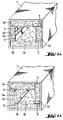
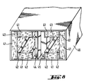
- the sheath shown in Figure 1a or Figure 1b comprises a metal casing 1, one or more sets of four insulating glass wool panels coated on their inner face (2a) with a protective sheet of glass fleece and flipped over their transverse side apparent (2b) by said sheet, and comprises four metal assembly profiles 3 in Z for holding the insulating panels in the sheath.
- the wings of the profiles used can be of the same length as the edge of the insulating panels (figure 1a) or can be of smaller dimension (figure 1b).
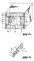
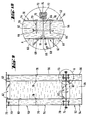
- the sheath shown in Figure 2a corresponds to the sheath shown in Figure 1a in which the "classic" Z-shaped assembly profiles have been replaced by particular Z-shaped profiles whose wings are folded at their free end so as to form a bulge 4; these particular profiles are supported on the casing of the sheath at two points (the end of the bulge and the core of the profile) and make it possible to avoid the problems of condensation between the metal wall and the profiles.
- Each profile also has an angle ⁇ between each wing and the core slightly less than 90 ° so as to allow positioning of the profile core parallel to one face of the sheath and the positioning of the panels perpendicularly to each other while lightly pinching the panels.
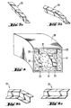
- FIG. 3a represents a ribbon 5 of mineral felt 6 coated with a protective sheet 7 glued and rebound, the ribbon of mineral felt being obtained according to known methods and the rebound being carried out by means of deflector-shaping rollers after application a protective sheet on the underside of the ribbon, this sheet being wider than the face in question.
- the rim is made on the side faces 8 in the direction of travel of the ribbon and on the parts 9 of the upper face adjacent to these side faces.
- Panels 10, 11, 12, 13, 14, 15 are then cut along the dotted lines indicated in FIG. 3a to internally coat the envelope with a sheath of rectangular section in order to obtain a sheath according to the invention. This sheath is produced (FIG.
- FIG. 4 represents a sheath according to the invention having a curvature, this sheath comprising a casing 20, insulating panels coated with a protective sheet on their internal face and flanged 21, and assembly profiles 22 in Z which can possibly be have folded edges.
- the assembly profiles used are bent in one or more places in order to follow the curvature of the sheath. In order to bend these sections, it suffices to cut the two wings of the sections along a chosen generatrix (dashed line in FIG. 5a and in FIG. 6a) and to bend the core of the section along this generatrix (FIGS. 5a and 5b, 6a and 6b).
- the insulating panels are also cut or bent to follow the curves of the sheath.
- FIG. 7a schematically shows a top view of the contour of a sheath according to the invention having changes in section.
- the internal coating of this sheath is carried out (FIG. 7b) by returning, by the widest side of the sheath, the lower insulating panel coated with a protective sheet on its internal face and flipped 30 (sheath envelope not shown ), by placing, on the longitudinal edges of this panel, assembly profiles (31, 32) in Z, one of the profiles 31 being folded in several places (after cutting the wings of the profile according to generatrices according to the principle illustrated in FIGS.
- the side panel 33 may be in one piece and have folds along V-shaped notches previously made in the panel or it may be three panels whose edges are cut so as to come into contact with each other , these edges being optionally joined by means of assembly profiles with an approximately T-shaped section whose angle between the core and each of the wings is adapted to the angle between the assembled panels.
- the sheath shown in FIG. 8 comprises a metal casing 40, insulating panels coated on their internal face with a protective sheet and flanged 41, assembly profiles 42 in Z for mounting the panels and a slide 43 consisting of two insulating panels glued to each other, the slide thus obtained being coated with a protective sheet on its two main faces, at least one of the edges transverse to the direction of flow of the sheath of this slide being enclosed in an assembly of two profiles (44, 45) in Z fixed to one another in one of their wings, for example by welding or gluing.
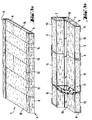
- the assembly shown in Figure 9 comprises two ducts with rectangular section 50, 52 (one of them being partially shown) assembled end to end.
- Each sheath comprises an envelope 54 with a thickness for example of 1 mm.
- This sheath is internally coated with insulating panels 56 based on glass wool or rock with a thickness for example between 20 and 100 mm.
- the internal face of the panels is optionally coated with a fire-resistant layer 60, for example in the form of a glass cloth, this layer also making it possible to clean the interior of the sheath.
- Each panel 56 comprises two profiles 62 with a thickness for example of 0.7 mm, the core 64 of each profile being in direct contact with only part of a transverse face 65 of the panel, one of the wings 66 penetrating into the insulating material and the other wing 68 covering part of the internal face of the panel (FIG. 10).
- the creation of thermal bridges between the outside and the inside of the sheath is avoided due in particular to the absence of metallic material between the flange of the profile 66 inserted in the panel and the envelope of sheath.
- the panels can for example be fixed by screws (for example self-supporting screws) 70 piercing the envelope of the sheath, part of the insulating material and the wing of the profiles pressed into the insulating material (the thermal bridges at the level of these very punctual elements being relatively unimportant).
- the panels can also be fixed using other screws or devices (such as keys 76 and washers 78 shown in Figure 9) placed for example in the middle of the panel.
- the two sheaths can be connected to each other, as shown more specifically in Figure 10.
- the envelope of each sheath is folded at each of these ends so as to form flanges 72 allowing its assembly with another sheath.
- the edges of two adjacent sheaths are symmetrical in relation to the plane perpendicular to the axis of the sheaths and in the space delimited by these edges is placed a seal 73; a sliding element 74 maintains the joined edges.
- Such flanges can be provided on the end of each face of the sheath.
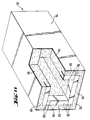
- the sheath shown in Figure 11 is similar to the sheath shown in Figure 9 (the common elements are designated by the same references and this sheath is not provided with screws or flanges for assembly, the assembly of the panels being done for example by gluing or by profiles not shown).
- the coating (the profiles) of the panels of the sheath according to the invention covers, on certain panels, only a part of the transverse edges 80 facing the flow channel of the sheath , this part being essentially the part of the edges directly exposed to the air circulating in the sheath.
- the sheath according to the invention can be used in any ventilation installation and the insulating panels according to the invention can be used in any type of ventilation sheath.
Landscapes
- Engineering & Computer Science (AREA)
- General Engineering & Computer Science (AREA)
- Mechanical Engineering (AREA)
- Chemical & Material Sciences (AREA)
- Combustion & Propulsion (AREA)
- Duct Arrangements (AREA)
- Thermal Insulation (AREA)
- Building Environments (AREA)
- Thermally Insulated Containers For Foods (AREA)
- Application Of Or Painting With Fluid Materials (AREA)
- Refrigerator Housings (AREA)
Applications Claiming Priority (4)
| Application Number | Priority Date | Filing Date | Title |
|---|---|---|---|
| FR9512986A FR2740804B1 (fr) | 1995-11-03 | 1995-11-03 | Gaine de ventilation et panneau isolant utilise pour son revetement interne |
| FR9512986 | 1995-11-03 | ||
| SE9504476A SE505567C2 (sv) | 1995-12-14 | 1995-12-14 | Kanalelement för ventilationskanal med isolering och kantskoning |
| SE9504476 | 1995-12-14 |
Publications (2)
| Publication Number | Publication Date |
|---|---|
| EP0772009A1 true EP0772009A1 (de) | 1997-05-07 |
| EP0772009B1 EP0772009B1 (de) | 2002-05-22 |
Family
ID=26232305
Family Applications (1)
| Application Number | Title | Priority Date | Filing Date |
|---|---|---|---|
| EP96402293A Expired - Lifetime EP0772009B1 (de) | 1995-11-03 | 1996-10-29 | Lüftungskanal und Isolierplatten für seine Auskleidung |
Country Status (7)
| Country | Link |
|---|---|
| US (2) | US5975146A (de) |
| EP (1) | EP0772009B1 (de) |
| AT (1) | ATE217954T1 (de) |
| DE (1) | DE69621307T2 (de) |
| DK (1) | DK0772009T3 (de) |
| ES (1) | ES2175050T3 (de) |
| PT (1) | PT772009E (de) |
Cited By (2)
| Publication number | Priority date | Publication date | Assignee | Title |
|---|---|---|---|---|
| GB2471777A (en) * | 2009-07-08 | 2011-01-12 | Ursa Iborica Aislantes Sa | Thermal-Acoustic Insulation Panel |
| WO2022053700A1 (fr) * | 2020-09-14 | 2022-03-17 | Saint-Gobain Isover Iberica, S.L. | Panneau pour conduits de climatisation |
Families Citing this family (37)
| Publication number | Priority date | Publication date | Assignee | Title |
|---|---|---|---|---|
| CA2142190C (fr) * | 1995-02-14 | 1998-01-27 | Marc Lessard | Conduite d'exfiltration d'air use |
| ES2175050T3 (es) * | 1995-11-03 | 2002-11-16 | Saint Gobain Isover | Conducto de ventilacion y panel aislante utilizado para su revestimiento. |
| JP3352065B2 (ja) * | 1999-12-13 | 2002-12-03 | 双葉電子工業株式会社 | 蛍光表示管及びその駆動方法 |
| US6497255B1 (en) * | 2001-07-13 | 2002-12-24 | Carrier Corporation | Floor panel for air handling unit |
| US6497256B1 (en) * | 2001-07-13 | 2002-12-24 | Carrier Corporation | Thermal barrier for air handling unit (AHU) cabinet |
| PT1532391E (pt) * | 2002-06-24 | 2009-06-25 | Saint Gobain Isover | Painel de isolamento para conduta de distribuição |
| US7140396B2 (en) * | 2002-11-27 | 2006-11-28 | Johns Manville | Air duct containing an organic liner material |
| US7597534B2 (en) | 2003-03-20 | 2009-10-06 | Huntair, Inc. | Fan array fan section in air-handling systems |
| US11255332B2 (en) | 2003-03-20 | 2022-02-22 | Nortek Air Solutions, Llc | Modular fan housing with multiple modular units having sound attenuation for a fan array for an air-handling system |
| US7137775B2 (en) | 2003-03-20 | 2006-11-21 | Huntair Inc. | Fan array fan section in air-handling systems |
| US7044171B2 (en) * | 2003-05-28 | 2006-05-16 | James W. Betley | Exterior ductwork system |
| ES2256639T3 (es) * | 2003-10-06 | 2006-07-16 | Saint-Gobain Isover | Conducto de ventilacion y aire acondicionado. |
| JP4834550B2 (ja) * | 2003-10-06 | 2011-12-14 | サン−ゴバン・イソベール | 空調または換気チャネル |
| US20050092384A1 (en) * | 2003-10-29 | 2005-05-05 | Superior Air Ducts | Semi-flexible air duct |
| ES2243119B1 (es) * | 2003-11-03 | 2007-02-16 | Saint-Gobain Cristaleria, S.A. | Rebordeado mediante recubrimiento de paneles para construccion de conductos de aire acondicionado. |
| US8511978B2 (en) * | 2006-05-02 | 2013-08-20 | United Technologies Corporation | Airfoil array with an endwall depression and components of the array |
| EP2053320A1 (de) * | 2007-10-24 | 2009-04-29 | P3 S.r.l. | Verbindungssystem zur Verbindung Endpaneelen aus einem Schalldämmmaterial |
| PL2260153T5 (pl) * | 2008-03-04 | 2024-03-04 | Rockwool A/S | Zabezpieczenie przeciwpożarowe elementu konstrukcyjnego |
| AU2010214924B2 (en) * | 2009-02-18 | 2015-10-22 | Walsh Intellectual Property Ltd. | A tubular duct member |
| CN102303366B (zh) * | 2011-07-01 | 2013-12-18 | 董光明 | 一种排气道的工业化生产线 |
| CA2805785A1 (en) * | 2012-05-02 | 2013-11-02 | Owens Corning Intellectual Capital, Llc | Duct liner |
| US9528261B2 (en) | 2013-01-09 | 2016-12-27 | Vita Nonwovens, Llc | Synthetic fiber insulation with facing |
| GB2514533B (en) * | 2013-03-08 | 2020-01-29 | Ronald Dalgarno Michael | Thermally insulated duct members |
| CN104125752A (zh) * | 2013-04-29 | 2014-10-29 | 鸿富锦精密工业(深圳)有限公司 | 导风罩 |
| US9371941B1 (en) | 2013-11-06 | 2016-06-21 | Ptm Manufacturing, Llc | Exterior ductwork system |
| CN106471317B (zh) * | 2014-05-07 | 2021-03-12 | 迈克尔·罗纳德·达尔加诺 | 输送管区段 |
| US11402121B2 (en) * | 2015-03-25 | 2022-08-02 | Sterling Custom Sheet Metal, Inc. | Insulated register box with boot rail adaptor |
| WO2017122068A1 (de) * | 2016-01-12 | 2017-07-20 | Zehnder Group International Ag | Kanalelement und kanalelement-system für ein lüftungssystem sowie eine damit ausgestattete gebäudehülle |
| ITUA20164322A1 (it) * | 2016-06-13 | 2017-12-13 | Sts Isolamenti S R L | Condotto di ventilazione silenziato |
| JP6752654B2 (ja) * | 2016-08-17 | 2020-09-09 | 株式会社荏原製作所 | 消音部材およびこの消音部材を用いた消音構造体 |
| US10976070B1 (en) | 2017-03-31 | 2021-04-13 | Albers Mechanical Contractors, Inc. | Foam core duct system protected by metal sleeves with integral flanges |
| DE102017210562A1 (de) * | 2017-06-22 | 2018-12-27 | Mahle International Gmbh | Schalldämmanordnung für eine Klimaanlage eines Kraftfahrzeugs |
| US10365005B2 (en) * | 2017-07-12 | 2019-07-30 | Fernando Surraco | Stainless steel foil laminated plastic HVAC duct and method of making same |
| WO2019212528A1 (en) * | 2018-05-01 | 2019-11-07 | Volpe Miles | Telescopic vent |
| US10731539B1 (en) * | 2018-05-01 | 2020-08-04 | Touchstone Resarch Labratory, Ltd | Composite exhaust flue |
| DE102021207777A1 (de) | 2021-07-21 | 2023-01-26 | Volkswagen Aktiengesellschaft | Luftkanalanordnung für ein Kraftfahrzeug, Kraftfahrzeug |
| US11927137B2 (en) * | 2022-03-21 | 2024-03-12 | Ge Infrastructure Technology Llc | System and method for insulating components in an exhaust gas flow from a gas turbine |
Citations (4)
| Publication number | Priority date | Publication date | Assignee | Title |
|---|---|---|---|---|
| DE1679519A1 (de) | 1967-12-19 | 1971-04-08 | Gruenzweig & Hartmann | Schallabsorbierender,waermedaemmender Luftkanal |
| FR2468076A1 (fr) * | 1979-10-18 | 1981-04-30 | Air Ind | Gaine de diffusion d'air de ventilation |
| WO1982003248A1 (en) * | 1981-03-20 | 1982-09-30 | Abc Corp Peabody | Sound attenuator |
| EP0074486A1 (de) * | 1981-09-01 | 1983-03-23 | Gretsch-Unitas GmbH Baubeschläge | Schieberlüftung mit einem motorbetriebenen Gebläse |
Family Cites Families (16)
| Publication number | Priority date | Publication date | Assignee | Title |
|---|---|---|---|---|
| US1063672A (en) * | 1911-07-19 | 1913-06-03 | William C Flannery | Process of constructing sewers, aqueducts, &c. |
| US3317074A (en) * | 1963-06-17 | 1967-05-02 | Douglas Aircraft Co Inc | Cryogenic containers |
| US3835606A (en) * | 1972-05-22 | 1974-09-17 | M Liberman | Combination ceiling tile and air duct structure |
| DE2808387B2 (de) * | 1978-02-27 | 1979-12-20 | Gutehoffnungshuette Sterkrade Ag, 4200 Oberhausen | Stahl-Beton-Verbundauskleidung für Schächte |
| US4280536A (en) * | 1978-08-23 | 1981-07-28 | Erich Gnant | Connecting device for insulated duct work |
| US4462618A (en) * | 1981-03-16 | 1984-07-31 | Wallace-Murray Corporation | Prefabricated double-walled metal chimney |
| DK164303C (da) * | 1990-05-14 | 1992-10-19 | Vik Consult | Isolering til et roer eller en kanal med en relativ lav overfladetemperatur og fremgangsmaade til fremstilling af isoleringen |
| GB2262192A (en) * | 1991-11-28 | 1993-06-09 | Zortech Int | Insulated duct for electric cables |
| US5487412A (en) * | 1993-05-26 | 1996-01-30 | Schuller International, Inc. | Glass fiber airduct with coated interior surface containing a biocide |
| US5379806A (en) * | 1993-05-26 | 1995-01-10 | Schuller International, Inc. | Fiber glass air duct with coated interior surface containing an organic biocide |
| US5783268A (en) * | 1993-08-11 | 1998-07-21 | Knauf Fiber Glass Gmbh | High air velocity duct board having minimal turbulence |
| US5654060A (en) * | 1995-06-16 | 1997-08-05 | The Boeing Company | High temperature insulation system |
| ES1032658Y (es) * | 1995-09-22 | 1996-10-16 | Cristaleria Espan | Perfileria de terminacion de uniones, para productos de lana de vidrio tipo "climaver plus". |
| ES2175050T3 (es) * | 1995-11-03 | 2002-11-16 | Saint Gobain Isover | Conducto de ventilacion y panel aislante utilizado para su revestimiento. |
| US5918644A (en) * | 1996-05-23 | 1999-07-06 | Haack; C. William | Air duct and method of making same |
| US6000437A (en) * | 1998-01-16 | 1999-12-14 | Certain Teed Corporation | Coated liner for curved ducts |
-
1996
- 1996-10-29 ES ES96402293T patent/ES2175050T3/es not_active Expired - Lifetime
- 1996-10-29 PT PT96402293T patent/PT772009E/pt unknown
- 1996-10-29 AT AT96402293T patent/ATE217954T1/de active
- 1996-10-29 DE DE69621307T patent/DE69621307T2/de not_active Expired - Lifetime
- 1996-10-29 EP EP96402293A patent/EP0772009B1/de not_active Expired - Lifetime
- 1996-10-29 DK DK96402293T patent/DK0772009T3/da active
- 1996-11-04 US US08/743,158 patent/US5975146A/en not_active Expired - Lifetime
-
1999
- 1999-08-16 US US09/374,108 patent/US6161593A/en not_active Expired - Lifetime
Patent Citations (4)
| Publication number | Priority date | Publication date | Assignee | Title |
|---|---|---|---|---|
| DE1679519A1 (de) | 1967-12-19 | 1971-04-08 | Gruenzweig & Hartmann | Schallabsorbierender,waermedaemmender Luftkanal |
| FR2468076A1 (fr) * | 1979-10-18 | 1981-04-30 | Air Ind | Gaine de diffusion d'air de ventilation |
| WO1982003248A1 (en) * | 1981-03-20 | 1982-09-30 | Abc Corp Peabody | Sound attenuator |
| EP0074486A1 (de) * | 1981-09-01 | 1983-03-23 | Gretsch-Unitas GmbH Baubeschläge | Schieberlüftung mit einem motorbetriebenen Gebläse |
Cited By (5)
| Publication number | Priority date | Publication date | Assignee | Title |
|---|---|---|---|---|
| GB2471777A (en) * | 2009-07-08 | 2011-01-12 | Ursa Iborica Aislantes Sa | Thermal-Acoustic Insulation Panel |
| GB2471777B (en) * | 2009-07-08 | 2015-04-29 | Ursa Ib Rica Aislantes Sa | Mineral wool thermal-acoustic insulation panel |
| WO2022053700A1 (fr) * | 2020-09-14 | 2022-03-17 | Saint-Gobain Isover Iberica, S.L. | Panneau pour conduits de climatisation |
| FR3114045A1 (fr) * | 2020-09-14 | 2022-03-18 | Saint-Gobain Isover Iberica, S.L. | Panneau pour conduits de climatisation |
| US12420531B2 (en) | 2020-09-14 | 2025-09-23 | Saint-Gobain Isover | Panel for air-conditioning ducts |
Also Published As
| Publication number | Publication date |
|---|---|
| DK0772009T3 (da) | 2002-09-16 |
| US5975146A (en) | 1999-11-02 |
| ATE217954T1 (de) | 2002-06-15 |
| PT772009E (pt) | 2002-10-31 |
| ES2175050T3 (es) | 2002-11-16 |
| DE69621307T2 (de) | 2002-12-12 |
| US6161593A (en) | 2000-12-19 |
| EP0772009B1 (de) | 2002-05-22 |
| DE69621307D1 (de) | 2002-06-27 |
Similar Documents
| Publication | Publication Date | Title |
|---|---|---|
| EP0772009B1 (de) | Lüftungskanal und Isolierplatten für seine Auskleidung | |
| EP0553012A1 (de) | Wasserdichte Dachabdeckvorrichtung | |
| EP1565625B1 (de) | Wärmedämmendes weiches material mit wenigstens einer durchlochten matte | |
| FR2740804A1 (fr) | Gaine de ventilation et panneau isolant utilise pour son revetement interne | |
| EP0433164B1 (de) | Wärmeisolierendes und feuerhemmendes Wandpaneel | |
| FR2582697A1 (fr) | Produits en fibres minerales sous forme de panneaux ou de rouleaux | |
| EP1130190B1 (de) | Schalldämmende Schicht für schwimmend verlegte Böden | |
| FR2469519A1 (fr) | Materiau pour la realisation de parois, cloisons ou similaires | |
| EP1426239B1 (de) | Dichtungs- und Schalldämpfungssplatte für ein Karosserieelement, wie ein Autotür | |
| WO1998042930A1 (fr) | Panneau d'isolation | |
| FR3011862A1 (fr) | Module de construction | |
| EP4536917A1 (de) | Innenwandverkleidung zur schallisolierung | |
| LU82391A1 (fr) | Plaque de verre isolante | |
| EP0557170B1 (de) | Wärmedämmende und wasserdichte Gebäudeeindeckung | |
| FR2847651A1 (fr) | Materiau d'isolation thermique et procede de pose d'un tel materiau | |
| EP1321594A1 (de) | Isolierendes Verbundmaterial | |
| FR2572503A1 (fr) | Procede de fabrication de radiateurs de chauffage par le sol | |
| FR2875520A1 (fr) | Panneau modulaire pour revetement de surface | |
| FR2977265A1 (fr) | Panneau composite pour l'isolation thermique de facade de batiments | |
| EP2719844B1 (de) | Konfektioniertes Verkleidungspaneel und Montageverfahren und Reparaturverfahren | |
| FR2854940A1 (fr) | Isolant multicouche | |
| FR2961536A1 (fr) | Assemblage comprenant au moins un panneau de construction avec au moins une entretoise intercalee en son interieur et procede de montage de l'assemblage | |
| EP1541777A1 (de) | Abdeckband zur Maskierung von Platte- oder Paneelanschlüsse | |
| EP0494029A1 (de) | Metall-Paneel zur Verkleidung oder Ausfüllung von tragenden Strukturen wie Fassaden oder Dächern | |
| FR2672914A1 (fr) | Dispositif de pontage. |
Legal Events
| Date | Code | Title | Description |
|---|---|---|---|
| PUAI | Public reference made under article 153(3) epc to a published international application that has entered the european phase |
Free format text: ORIGINAL CODE: 0009012 |
|
| AK | Designated contracting states |
Kind code of ref document: A1 Designated state(s): AT BE CH DE DK ES FI FR GB IT LI NL PT SE |
|
| 17P | Request for examination filed |
Effective date: 19970530 |
|
| 17Q | First examination report despatched |
Effective date: 20000119 |
|
| GRAG | Despatch of communication of intention to grant |
Free format text: ORIGINAL CODE: EPIDOS AGRA |
|
| GRAG | Despatch of communication of intention to grant |
Free format text: ORIGINAL CODE: EPIDOS AGRA |
|
| GRAH | Despatch of communication of intention to grant a patent |
Free format text: ORIGINAL CODE: EPIDOS IGRA |
|
| RAP1 | Party data changed (applicant data changed or rights of an application transferred) |
Owner name: SAINT-GOBAIN ISOVER |
|
| GRAH | Despatch of communication of intention to grant a patent |
Free format text: ORIGINAL CODE: EPIDOS IGRA |
|
| GRAA | (expected) grant |
Free format text: ORIGINAL CODE: 0009210 |
|
| REF | Corresponds to: |
Ref document number: 217954 Country of ref document: AT Date of ref document: 20020615 Kind code of ref document: T |
|
| REG | Reference to a national code |
Ref country code: GB Ref legal event code: FG4D Free format text: NOT ENGLISH |
|
| REG | Reference to a national code |
Ref country code: CH Ref legal event code: EP |
|
| REF | Corresponds to: |
Ref document number: 69621307 Country of ref document: DE Date of ref document: 20020627 |
|
| REG | Reference to a national code |
Ref country code: CH Ref legal event code: NV Representative=s name: KIRKER & CIE SA |
|
| GBT | Gb: translation of ep patent filed (gb section 77(6)(a)/1977) |
Effective date: 20020816 |
|
| REG | Reference to a national code |
Ref country code: DK Ref legal event code: T3 |
|
| REG | Reference to a national code |
Ref country code: PT Ref legal event code: SC4A Free format text: AVAILABILITY OF NATIONAL TRANSLATION Effective date: 20020726 |
|
| REG | Reference to a national code |
Ref country code: ES Ref legal event code: FG2A Ref document number: 2175050 Country of ref document: ES Kind code of ref document: T3 |
|
| PLBE | No opposition filed within time limit |
Free format text: ORIGINAL CODE: 0009261 |
|
| STAA | Information on the status of an ep patent application or granted ep patent |
Free format text: STATUS: NO OPPOSITION FILED WITHIN TIME LIMIT |
|
| 26N | No opposition filed |
Effective date: 20030225 |
|
| PGFP | Annual fee paid to national office [announced via postgrant information from national office to epo] |
Ref country code: DK Payment date: 20121010 Year of fee payment: 17 |
|
| PGFP | Annual fee paid to national office [announced via postgrant information from national office to epo] |
Ref country code: BE Payment date: 20121025 Year of fee payment: 17 Ref country code: DE Payment date: 20121211 Year of fee payment: 17 Ref country code: CH Payment date: 20121012 Year of fee payment: 17 Ref country code: FI Payment date: 20121010 Year of fee payment: 17 |
|
| PGFP | Annual fee paid to national office [announced via postgrant information from national office to epo] |
Ref country code: PT Payment date: 20120430 Year of fee payment: 17 Ref country code: SE Payment date: 20121011 Year of fee payment: 17 Ref country code: GB Payment date: 20121024 Year of fee payment: 17 |
|
| PGFP | Annual fee paid to national office [announced via postgrant information from national office to epo] |
Ref country code: AT Payment date: 20120927 Year of fee payment: 17 Ref country code: NL Payment date: 20121010 Year of fee payment: 17 |
|
| PGFP | Annual fee paid to national office [announced via postgrant information from national office to epo] |
Ref country code: ES Payment date: 20130911 Year of fee payment: 18 |
|
| PGFP | Annual fee paid to national office [announced via postgrant information from national office to epo] |
Ref country code: IT Payment date: 20130906 Year of fee payment: 18 |
|
| BERE | Be: lapsed |
Owner name: *SAINT-GOBAIN ISOVER Effective date: 20131031 |
|
| REG | Reference to a national code |
Ref country code: PT Ref legal event code: MM4A Free format text: LAPSE DUE TO NON-PAYMENT OF FEES Effective date: 20140429 |
|
| REG | Reference to a national code |
Ref country code: NL Ref legal event code: V1 Effective date: 20140501 |
|
| REG | Reference to a national code |
Ref country code: DK Ref legal event code: EBP Effective date: 20131031 |
|
| REG | Reference to a national code |
Ref country code: CH Ref legal event code: PL |
|
| REG | Reference to a national code |
Ref country code: SE Ref legal event code: EUG |
|
| REG | Reference to a national code |
Ref country code: AT Ref legal event code: MM01 Ref document number: 217954 Country of ref document: AT Kind code of ref document: T Effective date: 20131029 |
|
| GBPC | Gb: european patent ceased through non-payment of renewal fee |
Effective date: 20131029 |
|
| REG | Reference to a national code |
Ref country code: DE Ref legal event code: R119 Ref document number: 69621307 Country of ref document: DE Effective date: 20140501 |
|
| PG25 | Lapsed in a contracting state [announced via postgrant information from national office to epo] |
Ref country code: LI Free format text: LAPSE BECAUSE OF NON-PAYMENT OF DUE FEES Effective date: 20131031 Ref country code: GB Free format text: LAPSE BECAUSE OF NON-PAYMENT OF DUE FEES Effective date: 20131029 Ref country code: CH Free format text: LAPSE BECAUSE OF NON-PAYMENT OF DUE FEES Effective date: 20131031 |
|
| PG25 | Lapsed in a contracting state [announced via postgrant information from national office to epo] |
Ref country code: FI Free format text: LAPSE BECAUSE OF NON-PAYMENT OF DUE FEES Effective date: 20131029 Ref country code: AT Free format text: LAPSE BECAUSE OF NON-PAYMENT OF DUE FEES Effective date: 20131029 Ref country code: DE Free format text: LAPSE BECAUSE OF NON-PAYMENT OF DUE FEES Effective date: 20140501 Ref country code: PT Free format text: LAPSE BECAUSE OF NON-PAYMENT OF DUE FEES Effective date: 20140429 Ref country code: SE Free format text: LAPSE BECAUSE OF NON-PAYMENT OF DUE FEES Effective date: 20131030 Ref country code: NL Free format text: LAPSE BECAUSE OF NON-PAYMENT OF DUE FEES Effective date: 20140501 |
|
| PG25 | Lapsed in a contracting state [announced via postgrant information from national office to epo] |
Ref country code: BE Free format text: LAPSE BECAUSE OF NON-PAYMENT OF DUE FEES Effective date: 20131031 |
|
| PG25 | Lapsed in a contracting state [announced via postgrant information from national office to epo] |
Ref country code: DK Free format text: LAPSE BECAUSE OF NON-PAYMENT OF DUE FEES Effective date: 20131031 |
|
| PG25 | Lapsed in a contracting state [announced via postgrant information from national office to epo] |
Ref country code: IT Free format text: LAPSE BECAUSE OF NON-PAYMENT OF DUE FEES Effective date: 20141029 |
|
| REG | Reference to a national code |
Ref country code: FR Ref legal event code: PLFP Year of fee payment: 20 |
|
| REG | Reference to a national code |
Ref country code: ES Ref legal event code: FD2A Effective date: 20151127 |
|
| PG25 | Lapsed in a contracting state [announced via postgrant information from national office to epo] |
Ref country code: ES Free format text: LAPSE BECAUSE OF NON-PAYMENT OF DUE FEES Effective date: 20141030 |
|
| PGFP | Annual fee paid to national office [announced via postgrant information from national office to epo] |
Ref country code: FR Payment date: 20151022 Year of fee payment: 20 |